Etic Telecom RFM-E-400 User manual

DOC_DEV_RFM_User Guide_A
RFM
Router Fleet Manager
_________________
USER GUIDE
_________________

Page 2 DOC_DEV_RFM_User Guide_A
The Router Fleet Manager RFM product family is manufactured by
ETIC TELECOM
13 Chemin du vieux chêne
38240 MEYLAN
FRANCE
In case of difficulty in implementing the product, you can contact your reseller, or contact our customer
support service:
TEL : + (33) (0)4-76-04-20-05
E-mail : hotline@etictelecom.com
web : www.etictelecom.com

DOC_DEV_RFM_User Guide_A Page 3
DECLARATION OF CONFORMITY
The manufacturer, ETIC Telecom –13 chemin du vieux chêne –38240 Meylan –France, Hereby declares
under sole responsibility that the listed devices conform to
-the Radio Equipment Directive (RED) 2014/53/UE,
-the Restriction of the use of certain Hazardous Substances (RoHS) Directive 2011/65/UE.
Type of device: Router Fleet Manager
Models: RFM-E-400
Part Number: 1061000
The harmonized standards to which this device complies are:
Standard
Title
EN 61000-6-2 2006
Immunity:
EN61000-4-2 Electrostatic Discharge
EN61000-4-3 RF Radiated Immunity
EN61000-4-4 EFT/Burst Immunity
EN61000-4-5 Surge Immunity
EN61000-4-6 RF Conducted Immunity
EN61000-4-8 Power Frequency Magnetic Field Immunity
EN 61000-6-4 2007
A1/2011
Emission:
EN55022 Radiated and conducted emission
EN 301 489-1 V1.9.2
EN 301 489-3 V1.6.1
EN 301 489-7 V1.3.1
EN 301 489-17 V2.2.1
EN 301 489-24 V1.5.1
Radio - EMC
EN 301 511 V9.0.2
EN 301 908-1 V6.2.1
EN 301 908-2 V6.2.1
EN 300 328 V1.9.1
EN 301893 V1.8.1
Radio - Spectrum
EN 60950-1/A2 2014
EN 62311 2008
Safety and Health
Date : 28th February 2021
Philippe Duchesne
Technical Director


TABLE DES MATIERES
DOC_DEV_RFM_User Guide_A Page 5
PRESENTATION............................................................................................................................7
1Aim of the document ........................................................................................................................................ 7
2Product identification ....................................................................................................................................... 7
3Specifications.................................................................................................................................................... 8
4Product presentation ...................................................................................................................................... 11
4.1 Application ........................................................................................................................................... 11
4.2 Main features.......................................................................................................................................11
4.3 General operation principles............................................................................................................... 13
INSTALLATION ...........................................................................................................................15
1Description ...................................................................................................................................................... 15
1.1 Dimensions .......................................................................................................................................... 15
1.2 Front face............................................................................................................................................. 15
1.3 Rear view.............................................................................................................................................. 15
1.4 Connectors........................................................................................................................................... 16
1.5 Push Button (PB) ................................................................................................................................. 16
1.6 Indicators ............................................................................................................................................. 16
2Safety instructions..........................................................................................................................................17
3Ventilation ....................................................................................................................................................... 17
4Grounding........................................................................................................................................................ 17
PARAMETRAGE..........................................................................................................................18


PRESENTATION
DOC_DEV_RFM_User Guide_A Page 7
PRESENTATION
1Aim of the document
This document describes the implementation of the Router Fleet Manager RFM.
In the remainder of the document, this product is designated simply by the word “RFM”.
2Product identification
The commercial name of the Router Fleet Manager is: RFM-E-400 (Part Number to be mentioned in the orders:
1061000).
The main features are summarized below:
RFM-E-400
WAN Ethernet
•
LAN Ethernet 10-100 Mb/s
4
USB
•
Power VAC
110-230

PRESENTATION
Page 8 DOC_DEV_RFM_User Guide_A
3Specifications
Main features
Dimensions
With feet: 50 X 220 X 220 mm (h, l, p)
Without feet: 44 X 220 X 220 mm (h, l, p)
Weight
Max 0.65 kg
Casing
Metallic
IP20 –IEC60529
Temperature
Storage: -40°/ + 85°C
In operation: -20°/ + 60°C (without the fan)
Humidity
10 à 95 % (without condensation)
Power
110 to 230 VAC
Consumption
2W
EMC
Immunity EN61000-6-2 :
EN61000-4-2 : ESD : 4 kV contact –8kV air
EN61000-4-3 : RF radiated : 10V/m < 2 GHz
EN61000-4-4 : Burst
EN61000-4-5 : Surge : 4KV line / earth
EN61000-4-6 : RF conducted
EN61000-4-8 : Magnetic fields
Emission EN61000-6-4 :
EN 55022 : RF conducted and radiated
Electrical safety
EN 60950-1
Hazardous substances
2011/65/UE (RoHS)
REACH

PRESENTATION
DOC_DEV_RFM_User Guide_A Page 9
WAN network
Ethernet
RJ45
Auto : 10/100 full & half duplex MDI/MDI-X
LAN network
Ethernet
RJ45 : 4 ports
Auto : 10/100 full & half duplex MDI/MDI-X
Routing / @IP /
IP routing
Routing tables
Static rules
RIP
Address translation (DNAT, SNAT, NAT 1:1)
@IP
WAN interface: DHCP client or fixed IP
LAN interface: DHCP server
DNS
WAN interface: compatible DYNDNS, No-IP or ETIC DNS
LAN interface: DNS relay
Redundancy
VRRP protocol RFC 3768

PRESENTATION
Page 10 DOC_DEV_RFM_User Guide_A
Safety
VPN tunnel
OpenVPN (TLS/SSL), IPSEC, L2TP/IPSEC, PPTP
Shared key or X509 certificate
Encryption 3DES & AES 128-192-256
Authentication: MD5 & SHA-1
Up to 100 VPN tunnels
(mix between & OpenVPN IPSEC possible)
Firewall
Stateful packet inspection (SPI : 50 rules)
Filtering @ IP and ports number
Remote access
Up to 25 users
Login, Password and certificate (optional)
Access rights to individualized equipment
Log
Time stamped
Events: connection, restart, alarms
Miscellaneous
SNMP
MIBs available :
RFC1213-MIB (MIB-2)
Traps SNMP
Configuration
Web server
Management
Saving configurations
Product reset for return to factory configuration

PRESENTATION
DOC_DEV_RFM_User Guide_A Page 11
4Product presentation
4.1 Application
The RFM-E-400 simplifies the management of your fleet of RAS Machine Access Boxes by automating the
update of remote sites maintained and by centralizing in the RFM the management of access rights for each
operator.
The RFM-E-400 is an option of the M2Me remote maintenance solution which allows faster and safer
management of a fleet of RAS. The RFM mainly targets medium/large fleets of RAS.
NOTE: the interconnection of an RFM on a existing fleet of RAS, presupposes a significant charging time. This
load time includes the creation ex nihilo in the RFM of all remote maintainer users as well as the ex nihilo creation
in the RFM of all remote sites to be maintained.
The RFM is configured using a PC equipped with a web browser. No additional software is required. For
security reasons, access rights will be defined for the RFM.
The RFM is an industrial router on which is installed a management system for a fleet of routers. It therefore
has an HTML interface for configuring the network part identical to that of our range of routers as well as a
very simple configuration interface dedicated to fleet management.
NOTE: The detailed configuration of the RFM is described in a separate document available on our WEB site or
4.2 Main features
Management of the peering of remote sites to the RFM according to two cases:
•1st case: The fleet of RAS already exists:
A remote site database must be created in the RFM. Each site equipped with a RAS is attached to the RFM by
entering the RAS Product Key (PK) in the RFM (see RAS user manual) and a user ID of a remote maintainer. (If
the RAS is protected, you will also need to enter the administrator's password).
NOTE: in this specific case, it is advisable to call the Etic Telecom hotline service for a quicker start.
•2nd case: This is a new RAS in the fleet (recommended case).
This new RAS must be added to the RFM database.
When installing the RAS, you will need to fill in the "administration rights" section as follows:

PRESENTATION
Page 12 DOC_DEV_RFM_User Guide_A
The configuration of the RFM is then done by:
•Providing the PK (Product key) of the RAS.
•Providing the username and password of an administrator (in this case: azer and xxxxxx)
User management:
Users (remote sites maintainers) are created in the RFM where their access rights to the various sites are
managed.
RFM therefore enables a centralized policy for the management of user passwords, leading to more secure
management of the fleet (eg: regular updating of passwords made very simple and automated).
NOTE: RFM administrator does not necessarily know the remote maintainer passwords.

PRESENTATION
DOC_DEV_RFM_User Guide_A Page 13
RFM allows a user to be attached to an operating group subject to common rules (same remotely managed
sites, same rights on remote sites, etc.).
Distribution of the site address book to the new M2Me Client (An M2Me Client is provided to each new
remote site maintainer):
An M2Me Client launching a secure connection to the M2Me server automatically retrieves from the RFM
(permanently connected to the M2Me service) its updated list of remote sites as well as the access rights
given to it by the RFM administrator.
4.3 General operation principles
RFM is polling on the RAS fleet and provides the connected RASs with the latest update data on remote user
access rights.
Thus, the addition of users, the modification of their rights or their deletion is done automatically without
intervention on each site of the fleet.
Both the RFM and the M2Me Client installed on the remote user's PC are part of the secure M2Me Telecom
solution.
Thus, a remote maintainer using the RFM has the possibility of always having an up-to-date list of remote
sites.

INSTALLATION
DOC_DEV_RFM_User Guide_A Page 15
INSTALLATION
1Description
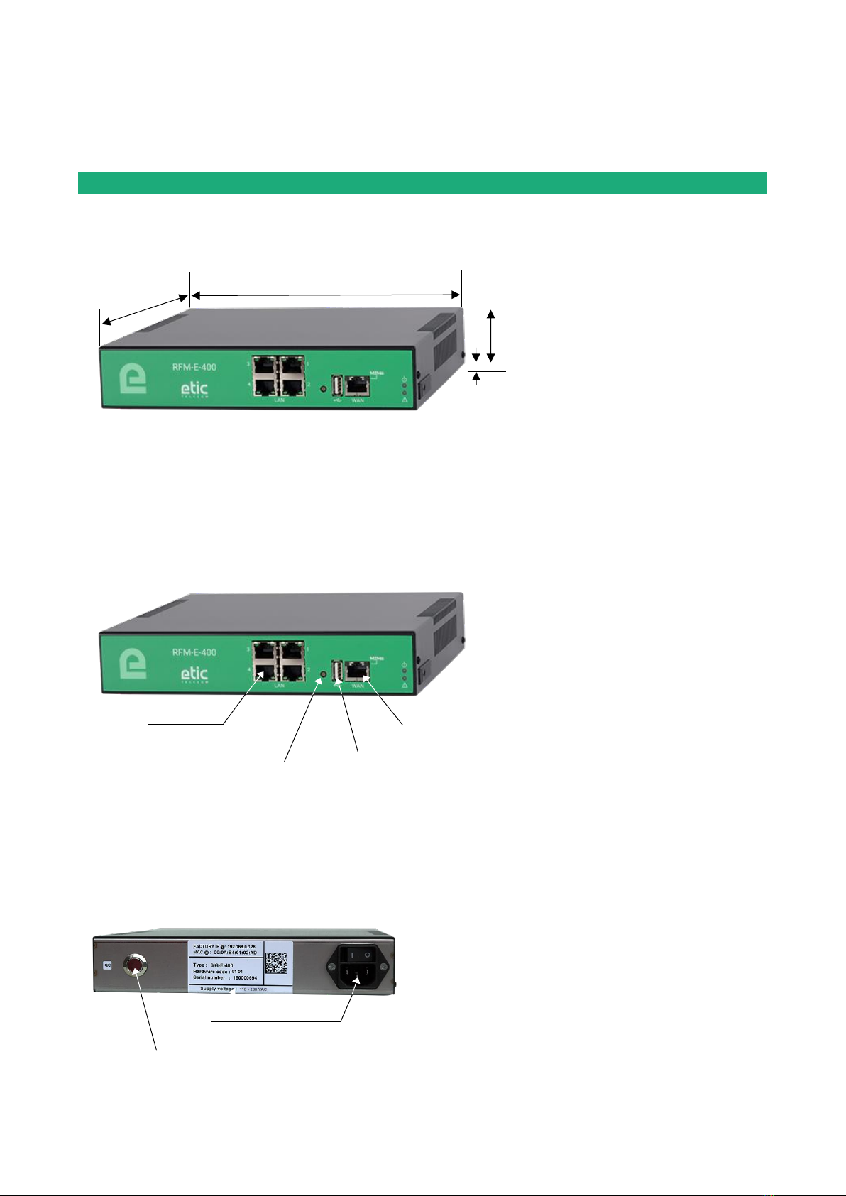
1.1 Dimensions
1.2 Front face
1.3 Rear view
220 mm
44 mm
6 mm
220 mm
LAN Ethernet
Push button B1
USB
WAN Ethernet
110-230 V AC power outlet
Push button B2

INSTALLATION
Page 16 DOC_DEV_RFM_User Guide_A
1.4 Connectors
Connecteur RJ45 Ethernet
Pin
Signal
Fonction
RJ45
1
Tx +
Emission polarity +
2
Tx -
Emission polarity -
3
Rx +
Reception polarity +
4
N.C
-
5
N.C
-
6
Rx -
Reception polarity -
7
N.C.
-
8
N.C.
-
1.5 Push Button (PB)
Push button of the front face B1
PB push
Indicator
Feature
10 secondes
5 pulses
ETIC TELECOM hotline is authorized to establish a remote
connection to the RFM within 1 hour.
1.6 Indicators
LED
According to models
Features
Indicator
Description
Opération
Off Power Off
Steady green In function
Slow flashing green Busy
Steady Red Start up (30s) - Otherwise serious hardware or software fault or
missing SIM card or missing recording media
Fast flashing Red Firmware loading in progress
Alarm
application
Reserved
M2Me
Connection
M2Me
Off Not connected to M2Me_Connect service
Slow flashing 2s Connection in process
Steady Green Connected
WAN
Ethernet
Left light
Off Not connected or interface disabled
Green Connected / light flash when data is present
LAN Ethernet
x 4
Left light
Off Not connected or interface disabled
Green Connected / light flash when data is present
Rear face push Button B2
PB push
Indicator
Feature
During operation
Blinking red
Temporary return to the Factory configuration.
(IP address : 192.168.0.128)
Current configuration is kept.
Simultaneously with
power on
Blinking red
Permanent return to Factory configuration.
Current configuration is lost unless it has been saved to a file.

INSTALLATION
DOC_DEV_RFM_User Guide_A Page 17
2Safety instructions
RFM must be installed by a qualified operator, in a cabinet or computer rack providing an enclosure against
fire.
RFM must only be connected to equipment that complies with IEC60950-1 or IEC62368-1 standards that meet
the following classifications:
•IEC60950-1 : limited power source and interconnection circuit of following type: TBTS –§2.2 et 2.5
•IEC62368-1 : ES1 & PS2
To avoid any risk of burns, it is strongly recommended to wear gloves when handling the product in
operation when the ambient temperature exceeds 30 ° C.
3Ventilation
The product is designed to be installed in a computer cabinet or rack.
To avoid any heating, in particular when the ambient temperature can rise in the cabinet, take care to leave a
space of 1 cm on each side and 2.5 cm above and below the product to facilitate the heat flow.
4Grounding
For reasons of safety and electromagnetic compatibility, the box must be connected to the protective earth of
the installation by means of its power cable.

PARAMETRAGE
The configuration of the RFM is described in detail in the following document: RFM Setup guide.
In case of difficulty, the hotline team (hotline@etictelecom.com // Tel : +33 (0) 4 76 04 20 00) is at your
disposal to get started with the RFM
13, Chemin du Vieux Chêne
38240 Meylan - France
Tel : +33 (0)4 76 04 20 00
www.etictelecom.com
Table of contents
Other Etic Telecom Network Hardware manuals


Popular Network Hardware manuals by other brands

ADTRAN
ADTRAN NetVanta SHDSL Network Interface Module quick start guide

APM
APM APE-502401a-1 Specification sheet

Enterasys
Enterasys Matrix 7GR4202-30 Hardware installation guide

Nortel
Nortel RLC Installation and administration guide

Viavi
Viavi NSC-100 Quick Card User Guide

Polycom
Polycom V2IU 6400-S user guide


