ETNA EFP Series User manual

EFP Series Sewage & Drainage Pump
User Manual

2
1. Handlng
The pump must be lfted and handled carefully by means of the handle and the lftng holes.
2. Desgn
The pump s avalable for the transfer of clean, polluted and turbd lquds, whch contan
suspended materals that do not exceed the followng dmensons. Its most common uses
are as follows: It can be used for dranng domestc waste water collectors, ran water
collectors, n flooded envronments, and n the excavatons and pts of the constructon
ndustry (EFP 26 DV or EFP 26 DT may be used). Vortex pallet models are also sutable for
the transfer of lquds that contan suspended flament materals.
3. Usage Lmts
EN 60335-2-41 standard prohbts usng the pump n tanks or swmmng pools that contan
people, and oblgates the use of the versons wth a 10m cable for outdoor use.
Pump workng condtons are not corresponded these flud propertes;
• Flud s over 35°C temperature, over 1000 kg/m3densty, over 1mm2/s knematc vscosty
• Chemcals that may be harmful to the pump materal and fluds contanng solds larger
than the pump permeablty descrbed n the table gven.
• Flammable and/or explosve fluds
• Other than these, potentally harmful substances and fluds
Note: The pumps must be submerged untl the mnmum submerson depth.
PUMP TYPE FLUID TYPE
Suspended Solids Submersion
Depth
(mm)
Quantity (%) Dimension (mm)
EFP 11 DP Clean Water / Waste Water < 10 < 10 300
EFP 11 D Clean Water < 5 < 6 300
EFP 11 DV Clean Water / Waste Water < 10 < 35 320
EFP 22 DP Clean Water < 8 < 6 260
EFP 22 D Clean Water / Waste Water < 20 < 15 260
EFP 26 DV Clean Water / Waste Water < 30 < 35 390
EFP 26 DT Clean Water / Waste Water < 40 < 40 385

3www.etna.com.tr
4. Electrcal Connecton
The pumps must be used wth an ETNA Hydropan electrcal panel.
5. Control of the Drecton of Rotaton
The correct drecton of rotaton s clockwse when lookng at the pump from above.
Observe and check the pump performance. Wth the correct drecton of rotaton, hgh
Q/H performance s ensured wth sngle channel and double channel versons, and a low
absorpton rate s provded wth vortex wheeled versons.
6. Mantenance
Please make sure that you power o f any mantenance s requred on the pump and call an expert
for the mantenance operaton.
The pump does not requre any routne mantenance. Cleanng the sucton flter (EFP 22D, EFP 26DV)
or the wheel may be requred. Remove the screws that hold the flters to access the wheel on the
models wth flters.
7. Safety Informaton
• The pump s not sutable for pumpng flammable or dangerous lquds.
• Do not use the energy cable to carry or lft your pump.
• Do not run the pump dry (out of the water).
• Snce the pump runs and stops automatcally, do not put your hands or other objects n
between when t s connected to the mans.
• Pay attenton to the lmtatons of use. Inapproprate use may damage the pump or
people.
• Ensure that the network voltage conforms to the value on the label.
• If the pump s three-phase, have the connectons to the electrc grd and the earthng
socket conducted by an expert (authorzed electrcan).
• Use a senstve phase relay (0.03A) as extra protecton aganst electrc shocks.
• Restrct the access of ndvduals, who are not authorzed to mantan the pump.
• Use the pump wthn the usage lmts defned on the label.
• Protect the pump aganst freezng.
• Protect the pump aganst potental blockages.
• We recommend that you wear gloves durng any acton conducted on the pump.

4
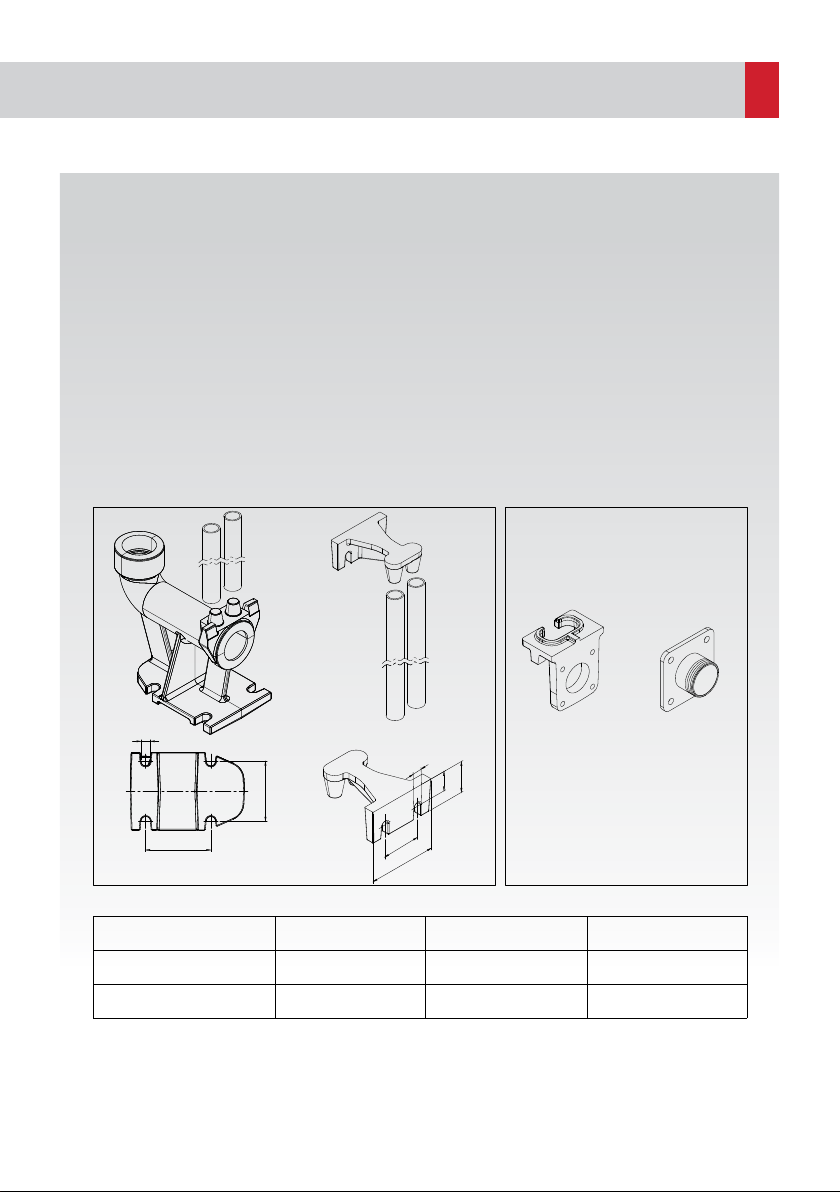
Fxed Installaton wth Sledge (Fgure 2)
• Fx the bottom secton of the sledge to the tank base as shown.
• Cut two 3/4" stanless ppes accordng to the dstance between the top secton of the
sledge and the fxed secton of the sledge and nstall (Fgure 4, Fgure 5).
• Mount the pump sledge flange and the connecton parts (Fgure 6). Attach a chan or a
rope to the handlng rng of the pump, slde the pump downwards from the sledge and
place t on the bottom part of the sledge.
• Connect the check valve and the valve to the horzontal secton n order to facltate access
to the dscharge ppe.
• Ths wll enable pump mantenance whle keepng the dscharge ppe connected to the
nstallaton
8. Troubleshootng
The motor starts runnng but the pump does not transfer: Make sure that water level s not
very low and the sucton nozzle or the dscharge ppe s not clogged.
If the transfer of the pump s reduced: Check for blockages and check the accuracy of the
rotaton drecton on the three-phase models.
If the pump runs ntermttently:
- The floater swtch adjusted wrong.
- The contaner of the pump s very small.
- The current wthdrawn from the electrcal panel s hgh.
- The pump or the ppes are clogged.
9. Nose
If the pump runs partally under water, the nose level should be less than 70 db(A), but ths
value s not applcable when the pump runs completely under water.
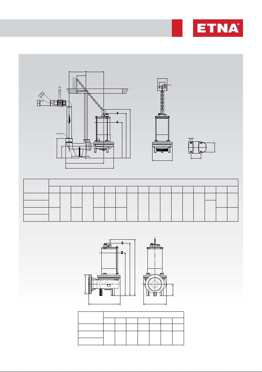
10. Installaton
The nner dameters and the szes of the ppes should allow flow. The water speed should be
hgher than 0.8-1m/sec n horzontal ppes, 1.6.m/sec n case of sand and floatng substances
and hgher than 2.5m/sec n vertcal ppes to prevent any possble blockage. The dscharge
ppe should never be smaller than the pump dscharge dameter. The vertcal ppe sectons
should be lmted and the horzontal ppe sectons should be slghtly nclned n the drecton
of the flow to prevent any depost that may cause the pump to stop.
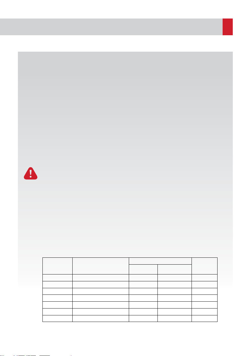
The pump should be held from ts handlng rng whle beng lfted or moved, and never be
lfted from ts cables snce ths may damage the pump. (Fgure 1) The maxmum mmerson
dept (ncludng the cable) should be 5m for EFP 11 and 10m for EFP 22 and EFP26.

5www.etna.com.tr
EXIT
ETNA
ANCHOR BOLT
UNION
G2''
BALL CHECK
VALVE
VALVE
SLEDGE FIXED BRACKET
ANGLE BRACKET
L50*50
ANGLE BRACKET
CONCRETE
WELL
GROUND
83 100 180
585
WELL TOP
ETNA
Fgure 1
Fgure 2
Fgure 3
Moble Installaton (Fgure 3)
• Prefer a chan or a rope that wll not rot, and connect t to the handlng rng of the pump. Always use
a chan or a rope to lower, lft or move the pump f you have a plastc or flexble dscharge ppe. Never
pull out from the power cable because t wll damage the pump. Connect the power cable to the
lftng chan or the rope usng proper connectors. Leave a sucent space for the cable to move snce
there wll be extra weght when the pump runs n case of a flexble dscharge ppe.

6
Immerson Sledge Installaton
• The mmerson sledge s a fttng that provdes ease of nstallaton and mantenance n
cases where the pump s requred to run on a fxed pont. As seen on Fgure 12 and Fgure
13, thanks to ts sledge system, the pump s easly suspended nto a well usng a chan
through ts stanless steel gude ppes and when t s drectly across from the flange located
at the bottom of the sledge, t sts onto the dscharge flange, and s ready for operaton.
Dscharge of the chamber, where the pump s located, s not requred durng ths process.
When mantenance for the pump s desred to be carred out, the pump s pulled up usng
a chan, cleaned by sprayng clean water wth a hose, easly taken out, and ts mantenance
s carred out. The pump s lowered back nto the well on the sledge after mantenance
and wll be easly made ready for operaton. It s recommended to use a strong chan when
suspendng the pump down on the sledge.
Mf
Cf
mf
Cp
Hf
Af
Gf
Bf
Dp2
Df2
110
100
16
DNm
EFP11 ve EFP11 D MONTAJ ŞEMASI
(HAREKETLİ)
EFP11 D MONTAJ ŞEMASI
(HAREKETLİ)
104
58
33
50
12
Sledge Fixed Elbow
Sledge Upper
Bracked
Sledge Flange Pump
Connection Part
3/4" P304 Pipe
Af
Gf
Bf
Mf
Cf
mf
Dp2
Df2
Cp
Hf
DNm
Fgure 5Fgure 4
MODEL Connection Diameter Suitable Pump Model Figure No
Sledge System Mounting Kit G2" EFP 11 DP - EFP 11 D 5 -6
Sledge System Mounting Kit G2" EFP 22 DP - EFP 22 D 5

7www.etna.com.tr
EFP 11 DP - EFP 11 D - EFP 22 DP and EFP 22 D Assembly Scheme
EFP 11 DV - EFP 26 DT and EFP 26 DV Assembly Scheme
TYPE DIMENSIONS (mm)
Af Bf Cf Cp Df1 Df2 Dp2 DNt Gf Hf I1 l2 ls Ls mf Mf DNm
EFP 11 DP 180
185
490
210
167 487 400
3/4" 100 130 110 100 58 104
390 465 2"
EFP 11 D
320EFP 22 DP 195 462 220 530 410 420 50
EFP 22 D
TYPE DIMENSIONS (mm)
Cf Df1 Df2 Hf mf Mf DNm
EFP 11 DV 450 200 253 120 320 425 2"
EFP 26 DT 546 220 300 110 403 503 65
EFP 26 DV
Mf
Cf
mf
Cp
Hf
Af
Gf
Bf
Dp2
Df2
Df1
Is
Ls
13
I1
I2
13
G2"
Mf
Cf
mf
Df1
Hf
DNm
Df2
DNm
I1
I2
13
Is
Ls
13
Mf
Cf
mf
Cp
Hf
Af
Gf
Bf
Dp2
Df2
Df1
Fgure 6
Fgure 7
Mf : (for continuous operation)
the lowest level
mf : the lowest operation level

8
183 195
665
700
HINGE
CONCRETE
565
620
CONCRETE WELL TOP
585
CONCRETE WELL TOP
GROUND
**
CONCRETE WELL
ANCHOR BOLT CONCRETE WELL
GROUND
150
565
BALL CHECK
VALVE
L50*50
ANGLE BRACKET
415
665
SLEDGE UPPER
BRACKED
SLEDGE FIXED ELBOW
585
WELL TOP
**
VALVE
UNION
Concrete Septc Tank and Waste Water - Dranage Pump İnstallaton Detals wth Sledge System
NOTE: Concrete well can be n the
desred sze. However, the well
top should be 620x585 so that the
sledge well cover suppled by
our frm can be mounted. Cover
chasss s ftted nto the well top,
and doweled from nsde.
** Alternatve connecton

9www.etna.com.tr
L50*50
ANGLE BRACKET
600
415
565
665
700
**
565
600
41550100
700
565
665
50
150 415
700
665
HINGE
COVER 2mm DKP
665*700
400
L50*50
ANGLE BRACKET
585
620
WELL TOP
585x620
SLEDGE TOP
BRACKET
**
DUBEL HOLE
575
CONCRETE
SURFACE
A
DETAIL A
5x10 METAL SHEET WILL BE
WELDED TO THE ENTIRE FRAME

10
NOTE

11 www.etna.com.tr
NOTE

Dudullu Organize Sanayi Bölgesi 2. Cadde No: 14
34775 Ümraniye-Istanbul / Turkey
Tel : +90 216 561 47 74 (Pbx) • Fax : +90 216 561 47 50
This manual suits for next models
7
Table of contents
Other ETNA Water Pump manuals
Popular Water Pump manuals by other brands

Rothenberger
Rothenberger TP25 Instructions for use

GÜDE
GÜDE ZWP 280-30 Original instructions

Pfeiffer Vacuum
Pfeiffer Vacuum HILOBE 1004 operating instructions

dosatron
dosatron D25RE10 Maintenance manual

BUSCH
BUSCH R 5 RD 0200 A instruction manual

Lowara
Lowara TKS Series Instructions for installation and use