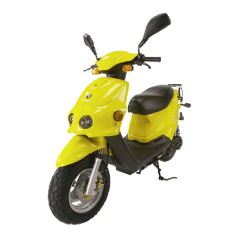
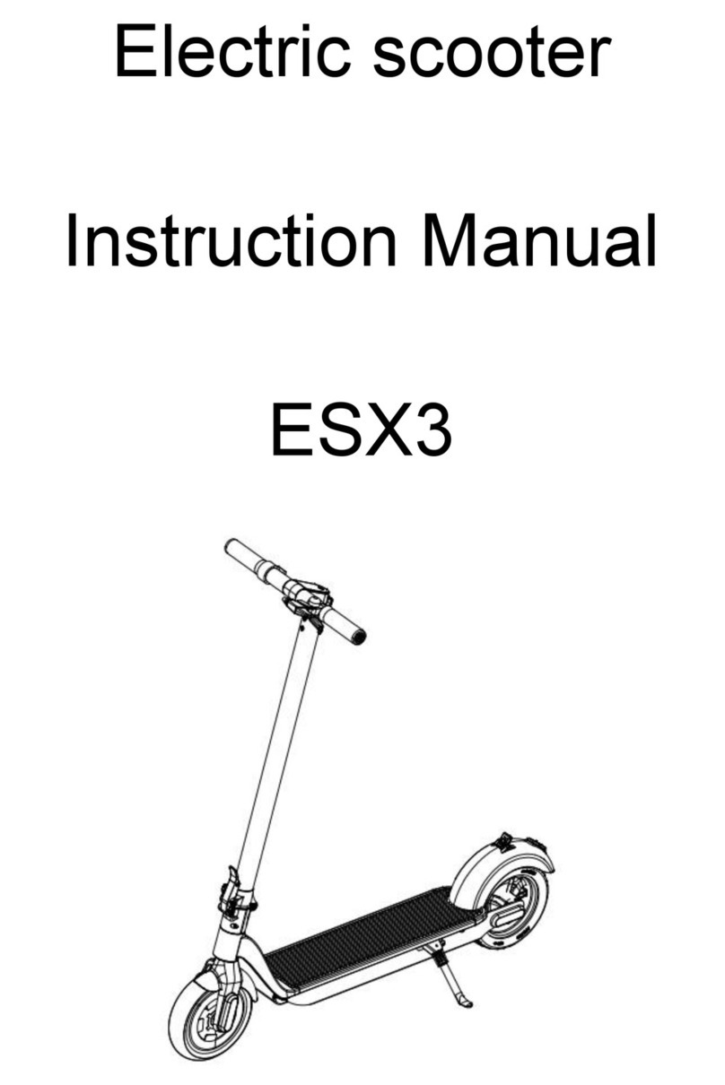
Eton EV3 E-MO User manual

SERVICE MANUAL
EV3
E-MO
E-TON POWER

E-MO
2009 by E-TON POWER TECH CO., LTD.
First edition, April 2009
All rights reserved.
Any reproduction or unauthorized use
without the written permission of
E-TON POWER TECH CO., LTD.
is expressly prohibited.
SERVICE MANUAL

IMPORTANT
This manual was produced by the E-TON POWER TECH CO., LTD., primarily for use by E-TON
dealers and their qualified mechanics. It is not possible to include all the knowledge of a mechanic
in one manual. Therefore, anyone who uses this book to perform maintenance and repairs on
E-TON vehicles should have a basic understanding of the mechanics and the techniques to repair
these types of vehicles. Repair and maintenance work attempted by anyone without this knowledge
is likely to render the vehicle unsafe and unfit for use.
E-TON POWER TECH CO., LTD., is continually striving to improve all of its models. Modifications
and significant changes in specifications or procedures will be forwarded to all authorized E-TON
dealers and will appear in future editions of this manual where applicabe.
NOTE:
Designs and specifications are subject to change without notice.
IMPORTANT INFORMATION
WARNING
NOTICE
TIP
This is the safety alert symbol. It is used to alert you to potential
personal injury hazards. Obey all safety messages that follow this
symbol to avoid possible injury or death.
damage to the vehicle or other property.
A TIP provides key information to make procedures easier or clearer.
A WARNING indicates a hazardous situation which, if not avoided,
could result in death or serious injury.
A NOTICE indicates special precautions that must be taken to avoid
Particularly important information is distinguished in this manual by the following notations:
* Product and specifications are subject to change without notice.

TABLE OF CONTENTS
SPECIFICATIONS
PERIODIC CHECKS AND
ADJUSTMENTS
CONTROLLER SYSTEM
BATTERY/ CHARGER
TROUBLESHOOTING
GENERAL INFORMATION
CHASSIS
CHK
ADJ
GEN
INFO
CHAS
ELECTRICAL SYSTEM
ELEC
–+
TRBL
SHTG
CONT
SPEC
BAT
CHA

CHAPTER 1
GENERAL INFORMATION
GENERAL INFORMATION 1-1......................................................
FRAME SERIAL NUMBER 1-1....................................................
MOTOR SERIAL NUMBER 1-1....................................................
IMPORTANT INFORMATION 1-2...................................................
REPLACEMENT PARTS 1-2......................................................
GASKETS, OIL SEALS AND O-RINGS 1-2.........................................
CHECKING THE CONNECTIONS 1-3..............................................
SPECIAL TOOLS 1-4.............................................................

IDENTIFICATION OF SCOOTER
1-1
GENERAL INFORMATION
SCOOTER IDENTIFICATION
FRAME SERIAL NUMBER
The frame serial number is stamped on the
chassis.
MOTOR SERIAL NUMBER
The serial number of the motor is stamped
on the portion of the left section of the motor
box.
TIP
The fourth to the sixth digits of these numbers
are for identifying the model; the remaining digits
constitute the production number of the unit.
TIP
Designs and specifications are subject to
change without notice.
GEN
INFO

IMPORTANT INFORMATION
1-2
IMPORTANT INFORMATION
REPLACEMENT PARTS
1. Use only genuine E-TON parts for all
replacements. Use the oil and/or grease
recommended by E-TON for assembly
and adjustment.
GASKETS, OIL SEALS AND O-RINGS
1. Replace all gaskets, seals and O-rings
when overhauling the rim. All gasket surfaces,
oil seal lips and O-rings must be cleaned.
2. Properly oil all mating parts and bearings
during reassembly. Apply grease to the oil
seal lips.
LOCK WASHERS/PLATES AND COTTER
PINS
1. Replace all lock washers/plates and cot-
ter pins after removal. Bend lock tabs along
the bolt or nut flats after the bolt or nut has
been tightened to specification.
BEARINGS AND OIL SEALS
1. Install the bearings and oil seals with
their manufacturer brands or numbers facing
outwards. (In other words, the stamped letters
should be on the side exposed to view.) When
installing oil seals, apply a light coating of
lightweight lithium base grease to the seal
lips. Put oil on the bearings when installing.
NOTICE
Do not use compressed air to spin the bea-
rings dry. This will damage the bearing surfa-
ce.
GEN
INFO
or

IMPORTANT INFORMATION
1-3
CHECKING THE CONNECTIONS
GEN
INFO
Check the leads, couplers, and connectors for
stains, rust, moisture, etc.
1. Disconnect:
•lead
•coupler
• connector
2. Check:
•lead
•coupler
• connector
Moisture Dry with an air blower.
Rust/stains Connect and disconnect sev-
eral times.
3. Check:
• all connections
Loose connection ĺ
ĺ
ĺ
Connect properly.
TIP
If the pin 1on the terminal is flattened, bend it
up.
4. Connect:
•lead
•coupler
• connector
TIP
Make sure all connections are tight.
5. Check:
• continuity (with the pocket tester)
TIP
• If there is no continuity, clean the terminals.
• When checking the wire harness, perform
steps 1 to 3.
• As a quick remedy, use a contact revitalizer
available at most part stores.

1-4
SE3200-5BA0-0FA1
SA6100-A26-0FA1
SA6100-A26-0FA2
SD4712-EGC2-0FA1
SD4711-EGC2-0FA1
Tool NO.
Tool name:
Six legs socket
Function:
To disassemble and assemble the nut
of front fork component.
Tool name / Function
Tool name:
Bearing inner puller set
Function:
To disassemble the bearing of front wheel.
8‚ 10‚ 12‚ 15‚ 17‚ 20‚ 22‚ 25‚ 30‚ 32/ mm
Tool name:
Oil seal & bearing installer set
Function:
Used for installing the bearing of the front
27, 32, 35, 40, 42, 45, 47, 48, 52, 58,
wheel and oil seal.
64/ mm
Tool name:
Tire valve driver
Function:
To disassemble and assemble an air
Double head (6.2mm& 5.4mm)
needle in the inner tube of a tire.
Tool name:
Tire lever component
Function:
To disassemble and assemble the inner
Specification:
11 inch and 15 inch.
tube of a tire.
Specification:
Specification:
Specification:
Picture
SPECIAL TOOLS
SPECIAL TOOLS
The following special tools are necessary for complete and accurate tune-up and assembly. Use
only the appropriate special tools as this will help prevent damage caused by the use of inappropriate
tools or improvised techniques.
GEN
INFO

SPECIAL TOOLS
1-5
SC9003-EGC2-0000
Tool name:
Function:
SC9004-EGC2-0000
Tool name:
Function:
SC130A-EGC2-0FG1
Tool name:
Function:
SC7200-EGC2-0FG1
Tool name:
Function:
GEN
INFO
Tool NO. Tool name / Function Picture
Motor checking tool
Testing the Hall data of motor.
Testing interface software
Testing interface connector
Only for testing driver.
Only for connecting the driver connector
and USB connector of the computer.
Instrument panel check tools
Only for testing the instrument panel
quality.

CHAPTER 2
SPECIFICATIONS
SPECIFICATIONS 2-1..............................................................
GENERAL SPECIFICATIONS 2-1.................................................
MAINTENENCE SPECIFICATIONS 2-2............................................
CONVERSION TABLE/ GENERAL TIGHTENING
TORQUE SPECIFICATIONS 2-4.....................................................
CONVERSION TABLE 2-4........................................................
GENERAL TIGHTENING TORQUE SPECIFICATIONS 2-4..........................
TIGHTENING TORQUES 2-5........................................................
CABLE ROUTING 2-6..............................................................
CHASSIS TIGHTENING TORQUES 2-5......................................................

GENERAL SPECIFICATIONS
2-1
SPECIFICATIONS
GENERAL SPECIFICATIONS
Dimensions
Overall length 1,550 mm (61.0 in)
Overall width 650 mm (25.6 in)
Overall height 1,000 mm (39.4 in)
Wheelbase 1,050 mm (41.3 in)
Minimum ground clearance 115 mm (4.5 in)
Minimum turning radius 1,600 mm (63.0 in)
Basic weight 50 kg (110.2 lb)
SPEC
Chassis
Frame type Steel tube FRAME
Caster angle 24°00'
Trail 73.5 mm (2.9 in)
Tire
Size front 2.25-14 27B
Size rear
Manufacturer front
Manufacturer rear
2.25-14 27B
Type front C-109R-X
Type rear C-109R-X
MAXXIS
MAXXIS
*Load in total weight of rider front
and accessories rear
225 kPa (2.25 kgf/cm ,32 psi)
Tire pressure (cold tire)
Maximum load* 98kg (215 LBS )
2
225 kPa (2.25 kgf/cm ,32 psi)
2
Brake
Front brake type Drum brake
operation Right hand operation
Rear brake type Drum brake
Left hand operation
Item Standard
operation

MAINTENANCE SPECIFICATIONS
2-2
CHASSIS
Front suspension
Front fork travel 50 mm (1.97 in)
Rear suspension
Shock absorber travel 30 mm (1.18 in)
Front wheel
Rim size 1.4 x 14"
Rim material
Rim runout limit
Aluminum
Rear wheel
Rim size 1.4 x 14"
Rim material Aluminum
Front drum brake
Leading, trailing ----
----
86.0mm
1.5mm
(3.39 in)
(0.06 in)
Type
85.0 mm (3.35 in)Brake drum inside diameter
3.0 mm (0.12 in)Lining thickness
46.3 mm (1.82 in)Shoe spring free length
Rear drum brake
Leading, trailing ----
----
86.0mm
1.5mm
(3.39 in)
(0.06 in)
Type
85.0 mm (3.35 in)Brake drum inside diameter
3.0 mm (0.12 in)Lining thickness
46.3 mm (1.82 in)Shoe spring free length
SPEC
Item Standard Limit
radial
lateral
2.0 mm
(0.08 in)
2.0 mm
(0.08 in)
Rim runout limit radial
lateral
2.0 mm
(0.08 in)
2.0 mm
(0.08 in)

MAINTENANCE SPECIFICATIONS
2-3
ELECTRICITY
Battery
Type
Battery capacity
Li-ion Mn battery
48.0 V/ 10AH
Lights X number
Headlight 12V 35/ 35W X1
Tail/ brake light
Fuse
Fuse (main)
Fuse (turn signal)
12V 21/ 5W X1
Turn signal light 12V 10W X4
30A
10A
Controller system
Charger
Power input
DC transformer output
48V ±10V
0A ~ 30A
SPEC
Item Standard Limit
voltage
current
12V ± 1V
7A ± 0.5A
48V ± 10V
25A ± 1A
voltage
current
Driver output voltage
115V/ 230VVoltage range
Motor
48V Brushless DC MotorType
current

2-4
SPEC
CONVERSION TABLE
All specification data in this manual are listed
in SI and METRIC UNITS.
Use this table to convert METRIC unit data to
IMPERIAL unit data.
CONVERSION TABLE
GENERAL TIGHTENING TORQUE
SPECIFICATIONS
This chart specifies tightening torques for stan-
dard fasteners with a standard ISO thread
pitch. Tightening torque specifications for spe-
cial components or assemblies are provided
for each chapter of this manual. To avoid
warpage, tighten multi-fastener assemblies in
a crisscross pattern and progressive stages
until the specified tightening torque is reached.
Unless otherwise specified, tightening torque
specifications require clean, dry threads. Com-
ponents should be at room temperature.
A: Distance between flats
B: Outside thread diameter
Ex.
METRIC MULTIPLIER IMPERIAL
** mm x0.03937 = ** in
2 mm x0.03937 = 0.08 in
METRIC TO IMPERIAL
Torque
Metric unit Multiplier Imperial unit
m·kg
m·kg
cm · kg
cm · kg
7.233
86.794
0.0723
0.8679
ft · lb
in · lb
ft · lb
in · lb
Weight kg
g
2.205
0.03527
lb
oz
Speed km/h 0.6214 mph
Distance
km
m
m
cm
mm
0.6214
3.281
1.094
0.3937
0.03937
mi
ft
yd
in
in
Volume/
Capacity
cc (cm3)
cc (cm3)
lt (liter)
lt (liter)
0.03527
0.06102
0.8799
0.2199
oz (Imp liq.)
cu · in
qt (Imp liq.)
gal(Impliq.)
Misc.
kg/mm
kg/cm2
Centigrade
(°C)
55.997
14.2234
9/5+32
lb/in
psi (lb/in2)
Fahrenheit
(°F)
A
(nut)
B
(bolt)
General tightening
torques
Nm m · kg ft · lb
10 mm 6 mm 6 0.6 4.3
12 mm 8 mm 15 1.5 11
14 mm 10 mm 30 3.0 22
17 mm 12 mm 55 5.5 40
19 mm 14 mm 85 8.5 61
22 mm 16 mm 130 13.0 94
CONVERSION TABLE/GENERAL
TIGHTENING TORQUE SPECIFICATIONS

TIGHTENING TORQUES
CHASSIS TIGHTENING TORQUES
2-5
SPEC
See chapter 3
“ADJUSTING THE
STEERING HEAD”
35
35
25
50
3.5
3.5
2.5
5.0
Nm m•kg ft•lb
M10
M10
M8
M25
1
1
4
2
10 1.0M6 4
10 1.0M6 1
10 1.0
M6 1
4 0.4
M6 24
4 0.4
M6 4
80 8.0
M14
M6
2
34 0.4
M6 24 0.4
35 3.5M10 1
25 2.5M8 2
10 1.0M6 1
4 0.4
35 3.5M10 1
45 4.5M10 1
M6 2
4 0.4M6 4
6 0.6M6 2
9 0.9
25.3
25.3
18.1
36.2
7.2
7.2
7.2
2.9
2.9
57.9
2.9
2.9
25.3
18.1
7.2
2.9
25.3
32.5
2.9
4.3
6.5M6 2
Part to be tightened Part
name Thread Q’ty
size
Tightening
torque Remarks
Chassis
Rear fork
Front fork
Rear shock absorber (up)
Bar footrest
Controller system
Horn
Hinge of seat
Body cover
Battery seat
Rear fork
Rear wheel axle
Rear shock absorber (down)
Main stand
Rear fender bracket
Body cover
Body cover
Front fork
Handle bar
Front shock absorber (down)
Body cover
Handle bar
Speedometer comp
Seat
Hinge of seat
Brake disk
Front brake arm cam/ brake arm
Nut
Nut
Bolt
Bolt
Bolt
Bolt
Bolt
Bolt
Bolt
Nut
Bolt
Bolt
Bolt
Bolt
Bolt
Nut
Bolt
Bolt
Bolt
Bolt
Bolt

1
2
3
4
5
6
7
8
9
10
11
A
B
C
D
1
3
4
5
6
7
A B C D
12
13
14
15
16
6
15
16
2
2-6
8
9
10
11
12
13
14
CABLE ROUTING SPEC
Wire harness
Cable brake, rear
Main switch lead
Horn lead
wire clamp
Turn signal lead
12 pin connector
EMI coil
Starter controller lead
DC 12V connecter
6 pin connecter
Positive battery lead
Negative battery lead
tail/brake light
Turn light connector
Main switch comp
Horn
EMI coil
Turn signal relay
UVW motor three-phases connecter

1
2
3
4
5
6
7
8
9
1
23
4
5
6
8
9
3
2
1
7
8
9
10
10
10
2-7
CABLE ROUTING SPEC
Right turn light lead
Right brake lead
Cable brake, front
Throttle lead
Headlight lead
Meter connector
Horn lead
Left brake lead
Cable brake, rear
Left turn light lead

CHAPTER 3
PERIODIC CHECKS AND ADJUSTMENTS
INTRODUCTION/ PERIODIC MAINTENANCE/ LUBRICATION 3-1.....................
REMOVING AND INSTALLING REAR BOTTOM COVER/ REAR FENDER 3-5.........
ADJUSTMENT FRONT/REAR BRAKE FREE PLAY 3-6...............................
CHECKING THE BRAKE SHOE 3-7.................................................
CHECKING THE STEERING SYSTEN 3-8...........................................
CHECKING THE FROENT FORK 3-9................................................
CHECKING THE REAR SHOCK ABSORBER 3-10....................................
CHECKING THE TIRES 3-10........................................................
CHECKING THE WHEELS 3-11......................................................
REPLACING THE HEADLIGHT BULB 3-12...........................................
REPLACING THE FRONT/ REAR TURN LIGHT BULB 3-13...........................
REPLACING THE TAIL LIGHT BULB 3-14............................................
SIDE COVER/ BODY COVER/ HEADLIGHT/ METER REMOVE AND INSTALL 3-2......
REMOVING THE SIDE COVER AND THE BODY COVER 3-2.......................
REMOVING HEADLIGHT/ METER/ METER SIDE COVER 3-4.......................
REMOVING SEAT/ BATTERY SEAT/ DRIVER ASSY/ BAR FOOTREST 3-3..........

3-1
This chapter includes all information necessary to perform recommended checks and adjustments.
These preventive maintenance procedures, if followed, will ensure more reliable motorcycle operation
and a longer service life. The need for costly overhaul work will be greatly reduced. This information
applies to motorcycles already in service as well as to new motorcycles that are being prepared for sale.
All service technicians should be familiar with this entire chapter.
INTRODUCTION/
PERIODIC MAINTENANCE/LUBRICATION
PERIODIC CHECKS AND ADJUSTMENTS
CHK
ADJ
INTRODUCTION
PERIODIC MAINTENANCE CHART FOR THE EMISSION CONTROL SYSTEM
1
2
7
5
6
No.
3
4
9
10
8
¥
¥
¥
¥
¥¥¥ ¥¥¥
¥¥¥ ¥¥¥
¥¥¥ ¥¥¥
¥¥¥ ¥¥¥
¥¥¥ ¥¥¥
¥¥¥ ¥¥¥
¥¥¥ ¥¥¥
¥¥¥ ¥¥¥
11
12
13
¥¥ ¥¥
¥¥ ¥
¥¥¥¥ ¥ ¥ ¥ ¥
¥¥¥¥ ¥ ¥ ¥ ¥
¥
¥
if necessary.
properly tightened.
ANNUAL
CHECK
ODOMETER READING (km)
CHECKS OR MAINTENANCE JOB
ITEM
Brake (drum)
• Check operation and adjust brake lever free play.
• Checking and replace the hose if necessary.
First 500km
or
1month
3000km
or
3 month
5500km
or
6month
8000km
or
9month
10500km
or
12 month
13000km
or
15 month
15500km
or
18 month
Tires • Check tread depth and for damage.
• Replace if necessary.
Wheel bearings • Check bearing for looseness or damage. Replace
Front fork • Replace if necessary.
• Check operation and correct if necessary.
Steering bearings • Replace if necessary.
• Check bearing play and steering for roughness.
• Lubricate with lithium-soap-based grease.
Rear shock absorber
assembly • Replace if necessary.
• Check operation and for oil leakage.
Main stand • Check operation and lubricate.
Battery • Check battery box for cracks or damage.
• Clean
Chassis fasteners • Make sure that all nuts, bolts and screws are
Moving parts
and cables • Lubricate.
Wheels • Check runout and for damage, and replace if
necessary.
Lights, signals
and switches
• Check operation and correct if necessary
• Adjust headlight beam.
Front and rear
brake switches • Check operation and correct if necessary.
Every 1,000km
Every 12,000km
• Replace the brake cable every two years or if cracked or damaged. If find the cracks or damage,
* Since these items require special tools, data and technical skills, have an E-TON dealer perform
the service.
• After 15,500 mileages has been reached or 18 months has been past, an additional maintenance
shall be conducted in every 2,500 km or 2 months.
• It should check and replace ahead of time in a dirt area or rainy day.
• Please check and replace ahead of time after by long riding distance or heavy load.
should replace the new one immediately.
TIP
Table of contents
Other Eton Scooter manuals

Eton
Eton Sport 150 User manual

Eton
Eton 2011 Viper 90R Silver Series User manual

Eton
Eton Beamer Scooter User manual

Eton
Eton sport 50 User manual

Eton
Eton MATRIX PN2H 50CC User manual

Eton
Eton Beamer User manual

Eton
Eton Sport 50 AV05W9-A User manual

Eton
Eton beamer R2-50 User manual

Eton
Eton Sport 150 User manual

Eton
Eton Beamer R4 User manual