ETQ TG1200 User manual

OWNER’S MANUAL
PREMIX GASOLINE ENGINE GENERATOR

PREFACE
Thank you for purchasing products from EASTERN TOOLS & EQUIPMENT, INC. We
appreciate your business. The following manual is only a guide to assist you and is not a
complete or comprehensive manual of all aspects of maintaining and repairing your
generator. The equipment you have purchased is a complex piece of machinery. We
recommend that that you consult with a dealer if you have doubts or concerns as to your
experience or ability to properly maintain or repair your equipment. You will save time
and the inconvenience of having to go back to the store if you choose to write or call us
concerning missing parts, service questions, operating advice, and/or assembly questions.
Our gasoline generators have some of the following features:
•Lightweight construction
•Air cooled
•Two-stroke gasoline internal combustion engine
•Recoil starter
•Thermal pushbutton reset circuit protector
•AC and DC outputs
The ETQ air-cooled gasoline generators are widely used when electrical power is scarce.
Our generators provide a portable mobile solution in supplying power for field operations
during project construction.
This manual will explain how to operate and service your generator set.
If you have any questions or suggestions about this manual, please contact your local
dealer or us directly. Consumers should notice that this manual might differ slightly
from the actual product as more improvements are made to our products. Some of the
pictures in this manual may differ slightly from the actual product as well. Eastern
Tools and Equipment, Inc. reserves the right to make changes at any time without
notice and without incurring any obligation.
2

CONTENTS
Page
TECHNICAL SPECIFICATIONS AND DATA 4
EQUIPMENT DESCRIPTION & KNOWING YOUR GENERATOR 5
SAFETYPRECAUTIONS 6
Electric shock and short circuit 6
Prevention from accidental burns 6
Refueling precautions 6
Engine safety precautions 7
Generatorsafety 7
PREPARATION BEFORE OPERATION 7
Gasolinepremix 7
Aircleaner 8
GROUNDING THE GENERATOR 8
OPERATING THE GENERATOR 9
Starting the engine 9
Connecting electrical loads and electrical capacity 10
Stopping the engine 11
RECEPTACLES 11
MAINTENANCE 12
Cleaning the generator 12
Storage 13
PARTLISTINGS 14
Generator 14
Generator engine 16
Recoil starter assembly 18
Electricalpanel 19
Airinletvalve 20
Generatorhead 21
TROUBLESHOOTING 22
LIMITEDWARRANTY 23
PRODUCT REGISTRATION CARD 25
3

4
TECHNICAL SPECIFICATIONS AND DATA
Technical specifications
Item Model TG1200
Type Brushless, revolving magnetic field, self –exciting, 2-pole,
single-phase
Voltage regulator Capacitor
Frequency (Hz) 60
Rated voltage (V) 120
Maximum output 1200 Watts
Rated Output 1000 Watts
Generator
Power factor (cos ϕ) 1.0
Engine type 2-Stroke
Displacement 63 Cubic centimeters (3.84 Cubic Inches)
Fuel tank capacity
(US gal) 1.01 Gallons
Continuous
operating hours 4.5 Hours
Fuel Type Premix 50 cups of Gasoline to one cup of 2 stroke oil
Ignition system Transistorized ignition (TCI)
Gasoline Engine
Starting system Recoil manual start
Dimensions
LxWxH) (in)
(
15” x 16” x 13”
Unit
Set
Dry weight (lb) Approx 55 lbs

5
EQUIPMENT DESCRIPTION & KNOWING YOUR GENERATOR
Please read this manual and follow the procedures covered in this manual. Become
familiar with the generators functions, applications, and limitations.
Below is a diagram of the locations of the various controls and functions of the generator
(6)
(4)
(9)
(1)
(7)
(3)
(2)
(11)
(12)
(8)
(5)
(1) FUEL TANK CAP (7) AIR CLEANER
(2) AC RECEPTACLE (8) CHOKE ROD
(3) THERMAL CIRCUIT PROTECTOR (9) SPARK PLUG
(4) ENGINE SWITCH (10) GROUND TERMINAL
(5) RECOIL STARTER (11) DC TERMINALS
(6) FUEL VALVE (12) DC CIRCUIT PROTECTOR
WARNING: DO NOT exceed the generator’s wattage / amperage capacity. Our
products are continuously being changed and improved. Every effort has been made to
ensure that information in the manual is accurate and up to date. However, we reserve
the right to change, alter or otherwise improve the product and this manual at any time
without prior notice.

6
SAFETY PRECAUTIONS
In order to ensure safety for the
consumer, please carefully follow
instructions on being careful with the
generators.
Operate the generator ONLY outdoors.
Never run the generator indoors as the
engine gives off poisonous carbon
monoxide, an odorless, and colorless
gas. Inhaling carbon monoxide will
cause nausea, fainting or death. Also,
keep the generator at least 3 feet away
from flammable matter for adequate
ventilation.
DANGER
Always properly ground the generator.
Failing to do so can result in
electrocution. Please refer to
“PROPERLY GROUNDING YOUR
GENERATOR”
ELECTRIC SHOCK AND SHORT
CIRCUIT
In highly conductive area such as metal
decking or steel work, use a ground fault
circuit interrupter (GFCI). Never touch
the generator if the generator is wet.
Also, never touch the generator if your
hand is wet. Never operate your
generator if the weather conditions call
for any type of precipitation such as rain,
snow, or fog.
PREVENTION FROM ACCIDENTAL
BURNS
Never touch the muffler and its cover
when the engine is running. Never touch
the muffler and cover after the engine
has been used, as the muffler remains
hot for a good period of time.
REFUELING PRECAUTIONS
Gasoline and its vapors are extremely
flammable. Do not smoke near gasoline
and keep gasoline away from generator
while the generator is running. When
adding fuel, turn the generator off and let

7
it cool at least 2 minutes before
removing the gas cap. Loosen gas cap
slowly to relieve the pressure in the tank.
Fill fuel tank outdoors and never overfill
the tank.
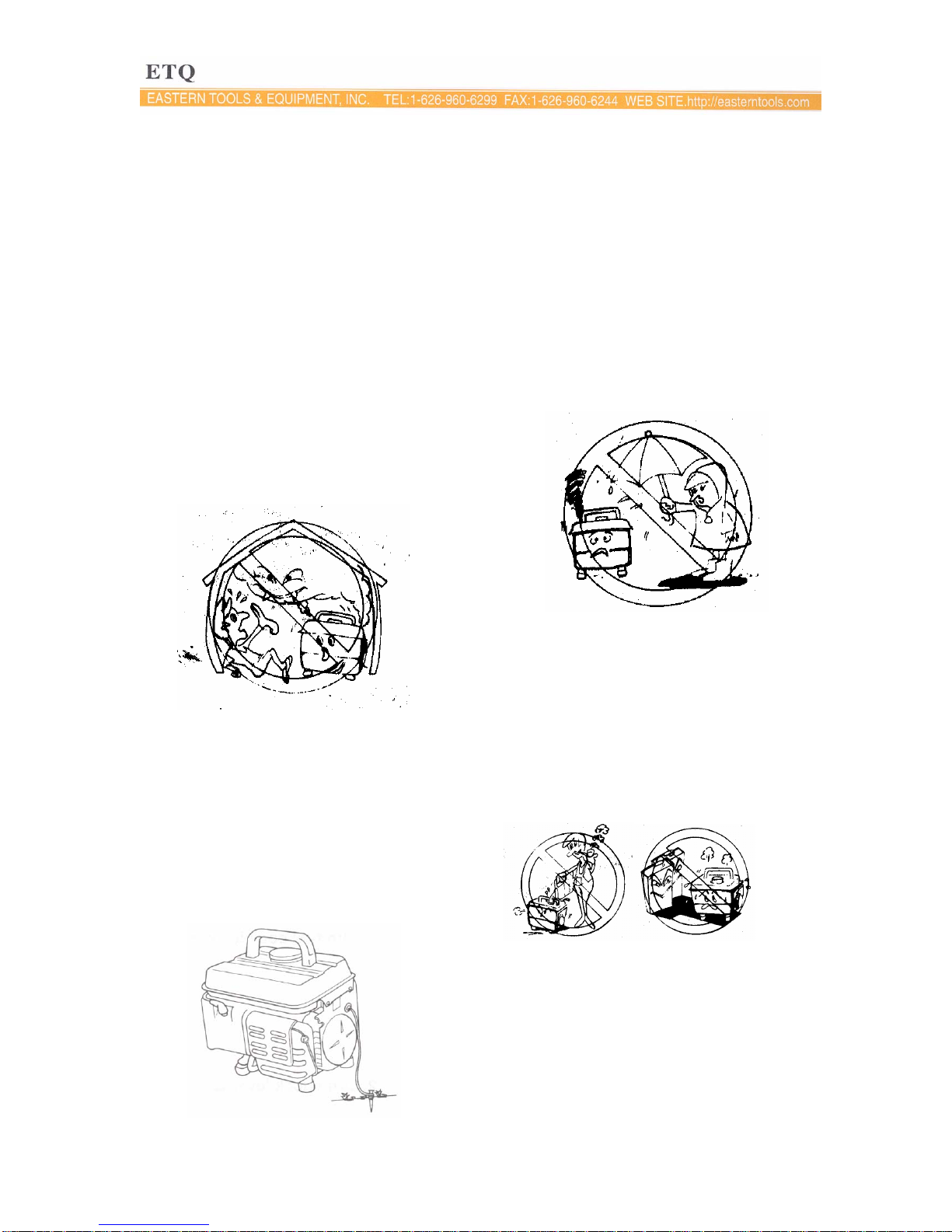
When storing gasoline or equipment
with fuel in tank.
Store away from appliances or
equipment that have a pilot light or other
ignition sources because they can ignite
gasoline vapors.
ENGINE SAFETY PRECAUTIONS
Do not touch hot surfaces. Allow
equipment to fully cool down before
touching.
After the generator has been run, the
engine produces heat. The temperatures
of the muffler and nearby areas can
reach or exceed 1600F. Severe burns
will occur on contact with skin.
Do not modify the generator in any way.
The generator supplies the rated voltage
and rated frequency at its governed
speed.
GENERATOR SAFETY
Never overload your generator as this
can damage your generator or the
electrical devices connected to it.
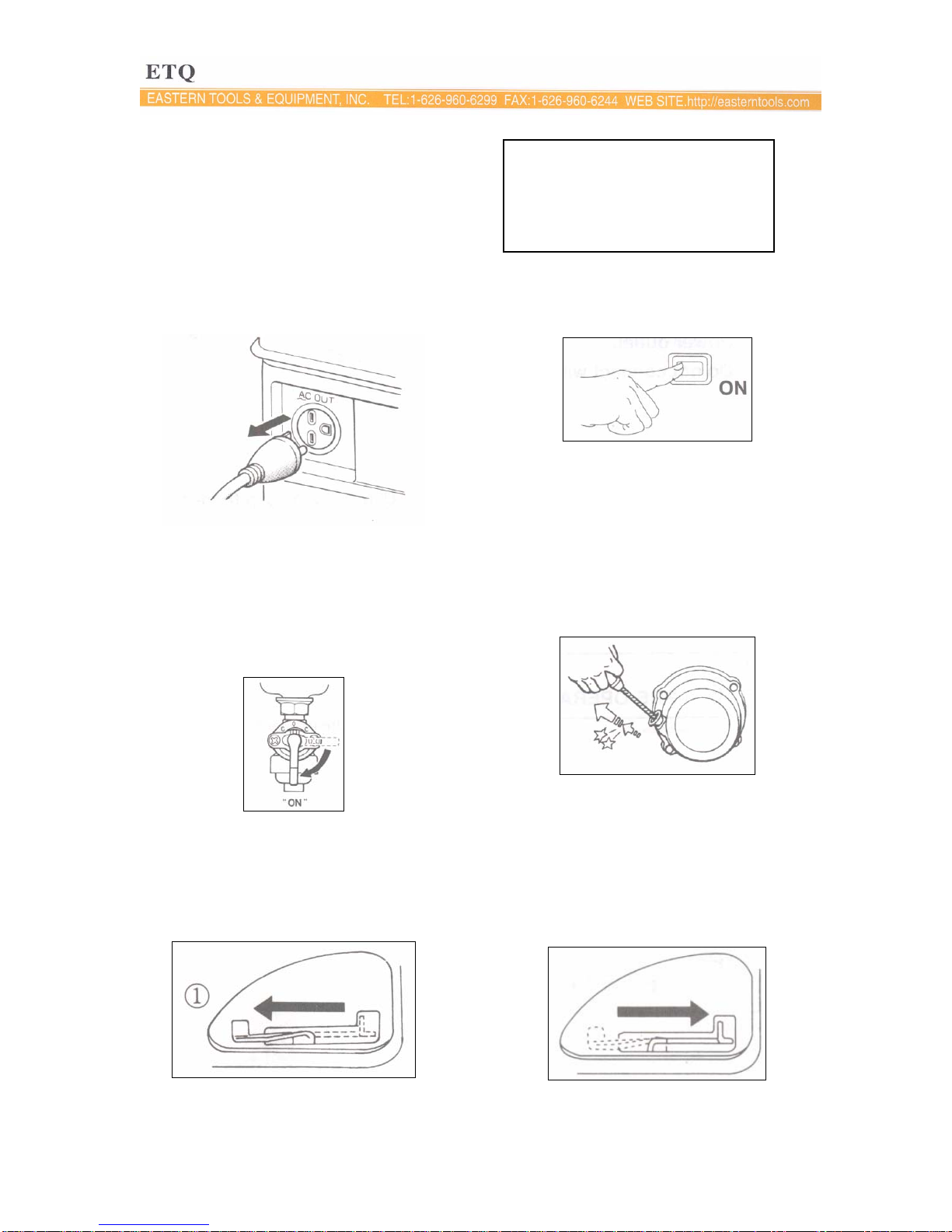
Do not start generator with electrical
devices connected to it. Start the
generator first and after the speed of the
generator stabilizes, electrical loads can
be applied to it.
When connecting electrical loads, make
sure the devices are “OFF” first before
connecting them. Keep the same
concept when disconnecting electrical
devices, make sure all devices are in the
“OFF” position before disconnecting.
Operate the generator on level surfaces
only. Inclined surfaces reduce the
effective lubrication of the engine.
Do not expose the generator to excessive
moisture, dust, dirt, or corrosive vapors.
PREPARATION BEFORE
OPERATION
Before starting the generator, verify the
following conditions.
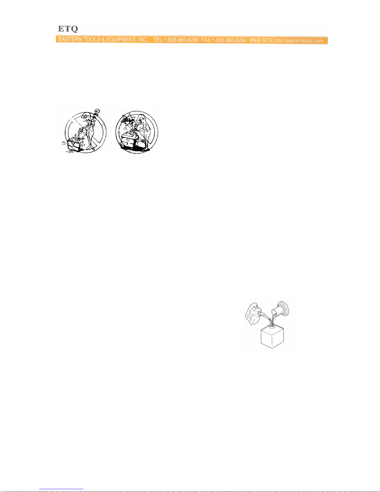
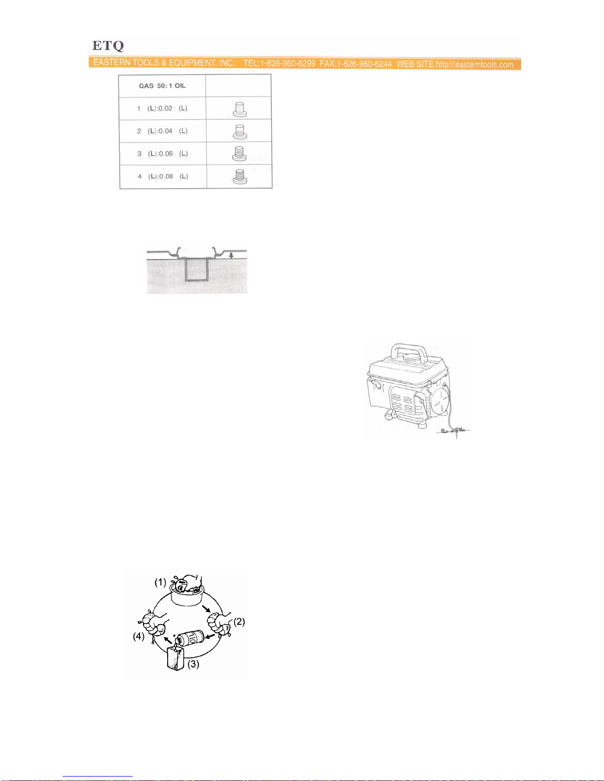
GASOLINE
•Add premixed oil and gasoline
and never fill the fuel tank
indoors. Also, be sure to install
the fuel tank cap on tight after
filling. Premix ratio should be
50 parts gasoline and 1 part 2
stroke oil. Use fuel tank cap to
measure oil.

8
•DO NOT overfill the fuel tank.
Always allow room for fuel
expansion.
•Never fill the fuel tank when the
engine is running or hot. Allow
the unit to cool for two minutes
before refueling. DO NOT light
a cigarette or smoke when filling
the fuel tank.
AIR CLEANER
•Unscrew the air cleaner cover
and remove the air cleaner cover.
•Check the air cleaner element to
be sure they are clean and in
good condition.
•If the air filter is dirty, remove
and clean the element.
oWash in solvent
oSqueeze
oSoak oil
oSqueeze dry
•Reinstall the air cleaner element
and secure the cover by setting
the cover spring.
GROUNDING THE
GENERATOR
The National Electric Code requires that
the frame of the generator and the
external electrically conductive parts of
the generator be connected to an
approved earth ground. Local codes
may differ and require other grounding
specifications. For this purpose, please
use a ground wire that attaches from the
frame to the generator unit. NOTE: The
grounding wire is not included with the
unit and could easily be fabricated by the
end user or local industrial supply store.
Using a No. 12 AWG (American Wire
Gauge) stranded copper wire to the
frame and to an earth-driven copper or
brass grounding rod provides sufficient
safety against shock. However, local
codes may differ. Contact a local
electrician to find out specifications for
grounding your generator.
Note: Grounding helps prevent
electrical shock if a ground fault
condition exists in the generator or in
faulty connected electrical devices.
Also, because the generator is rotating at
high speeds, static electricity tends to
buildup within the unit. Grounding
helps dissipate the static electricity
buildup often builtup in ungrounded
devices.

9
OPERATING THE
GENERATOR
STARTING THE ENGINE
Before starting the engine, verify that the
gasoline mix is full, and air filter is in
place. Also, disconnect any load from
the AC receptacle.
CAUTION! NEVER start or stop the
unit with electrical loads connected
AND with the connected devices
turned ON.
Figure 4. Engine switch on position
Figure 1. Disconnecting electrical devices
•Turn the fuel valve to the “On”
position (Figure 2).
Figure 2. Fuel Valve
•Place the choke lever in the
“CHOKE” position (Figure 3.).
Figure 3. Choke Positions
•Turn the engine switch to the
“ON” position (Figure 4).
•Pull the recoil starter grip lightly
until resistance is felt, then pull
hard. Warning: Do not allow the
starter grip to snap back against
the engine. Return it gently
(Figure 5.).
Figure 5. Recoil starting rope
Push the choke rod to the “OPEN”
position as the engine starts up (Figure
6).
Figure 6. Putting choke rod to “OPEN”

10
CONNECTING ELECTRICAL
LOADS AND ELECTRICAL
CAPACITY
After starting the generator, let the
engine warm up after connecting
electrical loads to it. Do not have any
electrical loads connected before starting
the generator.
Make sure all electrical devices are 60
Hz devices. Do not connect 50 Hz
devices to the generator.
Do not connect 3-phase loads to the
generator.
Do not overload the generator. Before
beginning your work, you must verify
that the rated (running) and surge
(starting) watts for the items you will
power at the same time are within the
generators operating capacity. Please
refer to the following Table 1. for
wattage / amperage ratings. Also, to
prolong the life of your generator,
sequentially add loads and permit the
generator to stabilize before adding
another load. Never exceed the capacity
of the generator.
Estimate how many surge (starting)
watts you will need. Surge wattage is
the short burst of power needed to start
electric motor-driven tools or appliances
such as a circular saw or refrigerator.
Below is an example of how the rated
and surge wattage can be estimated.
Example:
Tool or Appliance Rated
(Running)
Watts
Additional
Surge (Starting)
Watts
Television 500 500
Light (75 Watt) 75 20
Total 575 Total
Running Watts 520 Highest
Surge Watts
Total Rated (Running) Watts = 575
Highest Additional Surge Watts = 520
Total Generator Output Required = 1095
Table 1. Wattage reference chart
Tool or Appliance Rated
(Running)
Watts
Additional
Surge
(Starting)
Watts
Essentials
Light Bulb – 75 watt 75 -
Freezer 500 500
Heating/Cooling
Window Fan 300 600
Family Room
DVD / CD Player 100 -
VCR 100 -
Stereo Receiver 450 -
27 “ Color Television 500 -
Personal Computer w/17”
monitor 800 -
Other
Security system 180 -
AM / FM clock radio 300 -
½ HP Garage door opener 480 520
DIY / Job Site
Halogen work light 1000 -
Reciprocating Saw 960 960
½ HP Electric Drill 1000 1000
Note: wattages listed are only approximates. Check
your electrical device for actual wattage.

11
STOPPING THE ENGINE
•Unplug all the electrical loads from
the generator panel (Figure 2.).
Figure 2.
•Let the engine run at no-load for
several minutes to stabilize the
internal temperatures of engine and
generator.
•Turn the engine switch to the “OFF”
position (Figure 3.).
Figure 3.
•Turn the fuel valve to the “OFF”
position (Figure 4.).
Figure 4.
RECEPTACLES
This generator is equipped with the
following receptacles:
120 Volt AC, 15 Amp Receptacle
Figure 5. 120 Volt, 15 AmpReceptacle
Note: Please be sure to use electrical
cords that support the amount of wattage
being used. The electrical cords should
be able to handle 20 Amps of current at
125 Volts.

12
MAINTENANCE
Below is a maintenance schedule for the
generator.
SPARK PLUG
•Remove the spark plug
•Remove the carbon deposits
•Check for discoloration. Standard is
tan in color.
•Check spark plug gap
Gap measurements
.7~.8 mm (.028~.031 inches)
CLEANING THE GENERATOR
Generator maintenance consists of
keeping the unit clean and dry. Be sure
to store the unit in a clean and dry
environment, where it will not be
exposed to excessive dust, dirt, moisture
or any corrosive vapors. Cooling slots
should always be clean and free from
clogs.
Note: Do not use a garden hose to clean
the generator. Water can enter the fuel
and intake system and cause problems.
In addition, if water and dirt buildup on
the generators internal windings, the
resistance of these windings will
decrease.
•To clean the generator, use a damp
cloth to wipe the exterior surfaces.
•Use a soft bristle brush to loosen
caked on dirt of oil.
•Use a vacuum cleaner to pick up
loose dirt and debris.
•Compressed air (not to exceed 25
psi) may be used to blow away dirt.

13
STORAGE
The generator should be started at least once every week. If this cannot be done and you
must store the unit more than 30 days, please follow the following guidelines.
•Close the fuel valve; drain the fuel from the fuel tank (Figure 1).
Figure 1.
•Drain the fuel from the carburetor (Figure 2.).
Figure 2.
•Pull the starter grip carefully until resistance is felt (Figure 5.).
Figure 5.
•Store the generator in a clean area.

14
PARTS LISTINGS
Figure 1. Exploded view of entire generator

15
Table 1. Please refer to figure 1.
NUMBER DESCRIPTION PART NUMBER QTY.
1 Fuel tank ETQ1200TG1 1
2 Engine ETQ1200TQ2 1
3 Generator ETQ1200TG3 1
4 Exhaust pipe ETQ1200TG4 1
5 Front panel ETQ1200TG5 1
6 Carburetor ETQ1200TG6 1
7 Starting cover assembly ETQ1200TG7 1
8 Fuel control valve ETQ1200TG8 1
9 Air filter ETQ1200TG9 1
10 Seal ring dia.190 ETQ1200TG10 1
11 Air filter cover ETQ1200TG11 1
12 Fixed plate ETQ1200TG12 1
13 Gasket ETQ1200TG13 1
14 Gasket ETQ1200TG14 1
15 Pilot adjusting rod ETQ1200TG15 1
16 Pilot adjusting spring ETQ1200TG16 1
17 Screw 6x85 1
18 Screw M6x14 1
19 Screw M6X14 4
20 Screw M6x14 4
21 Screw M6x20 1
22 Spring washer dia.6 1
23 Screw 6x65 2
24 Gasket dia.6 1
25 Spring washer dia.6 1
26 Gasket dia.6 1
27 Fuel pipe ETQ1200TG17 1
28 Fuel pipe clip 2
29 Screw 6x20 2

16
Figure 2. Exploded view of generator engine.

17
TABLE 2. Please refer to figure 2 for diagram
NUMBER DESCRIPTION PART NUMBER QTY.
1 Crankshaft ETQ1200TG18 1
2 Crankcase (left) ETQ1200TG19 1
3 Crankcase (right) ETQ1200TG20 1
4 Flywheel ETQ1200TG21 1
5 Cylinder sleeve ETQ1200TG22 1
6 Cylinder head ETQ1200TG23 1
7 Piston ETQ1200TG24 1
8 Piston ring ETQ1200TG25 2
9 Needle bearing ETQ1200TG26 1
10 Piston pin ETQ1200TG27 1
11 Spring leaf / piston pin ETQ1200TG28 2
12 Gasket (cylinder bottom) ETQ1200TG29 1
13 Gasket (cylinder head) ETQ1200TG30 1
14 Spark Plug ETQ1200TG31 1
15 Cylinder air shroud ETQ1200TG32 1
16 Magneto ETQ1200TG33 1
17 Bearing 104 ETQ1200TG34 1
18 Speed regulating fork dia.47 ETQ1200TG35 1
19 Speed regulating fork ETQ1200TG36 1
20 Slip ring ETQ1200TG37 1
21 Slip ring ETQ1200TG38 1
22 Stand ETQ1200TG39 1
23 Oil seal dia. 20 ETQ1200TG40 2
24 Speed adjusting level ETQ1200TG41 1
25 Oil seal dia. 6 ETQ1200TG42 1
26 Speed adjusting level ETQ1200TG43 1
27 Shifter ETQ1200TG44 1
28 High voltage set ETQ1200TG45 1
29 Speed governing spring ETQ1200TG46 1
30 Speed governor gasket ETQ1200TG47 1
31 Shockproof boot ETQ1200TG48 2
32 Screw 6x113 ETQ1200TG49 2
33 Gasket dia. 6 ETQ1200TG50 1
34 Spring washer dia. 6 ETQ1200TG51 2
35 Nut M6x15 ETQ1200TG52 2
36 Gasket dia. 6 ETQ1200TG53 2
37 Spring washer dia 6 ETQ1200TG54 2
38 Screw M6x14 2
39 Screw M6x45 4
40 Screw M6x50 2
41 Screw M6x40 1
42 Screw M6x18 2

18
43 Gasket dia 10 ETQ1200TG55 1
44 Spring washer dia. 6 ETQ1200TG56 1
45 Nut M10 ETQ1200TG57 1
46 Nut M6 ETQ1200TG58 1
47 Screw M6x12 ETQ1200TG59 2
48 Spring washer dia. 6 ETQ1200TG60 2
49 Gasket dia. 6 ETQ1200TG61 2
50 Gasket dia. 3 ETQ1200TG62 2
51 Spring washer dia. 3 ETQ1200TG63 2
52 Screw M3 ETQ1200TG64 2
53 Screw M6x20 1
54 Spring washer dia. 6 1
55 Gasket dia. 6 1
56 Locating ring dia. 10 2
57 Locating sheet 1
58 Screw M6x20 4
FIGURE 3. Recoil starter assembly
TABLE 3. Please refer to figure 3 for diagram.
NUMBER DESCRIPTION PART NUMBER QTY.
1 Starting cover ETQ1200TG65 1
2 Starting handle ETQ1200TG66 1
3 Starting rope ETQ1200TG67 1
4 Torsional spring ETQ1200TG68 1
5 Claw ETQ1200TG69 1
6 Bearing plate ETQ1200TG70 1
7 Drive plate ETQ1200TG71 1
8 Spring clip ETQ1200TG72 1
9 Screw M6X12 1

19
FIGURE 4. Electrical panel assembly
TABLE 4. Please refer to figure 4 for diagram.
NUMBER DESCRIPTION PART NUMBER QTY.
1 Front panel ETQ1200TG73 1
2 Igniter ETQ1200TG74 1
3 Screw M4x20 1
4 On/Off switch ETQ1200TG75 1
5 Capacitor ETQ1200TG76 1
6 Capacitor clip ETQ1200TG77 1
7 Screw M4x10 2
8 Thermal circuit breaker ETQ1200TG78 1
9 Washer 1
10 Screw M4x10 1
11 Cover plate ETQ1200TG79 1
12 Receptacle ETQ1200TG80 1
13 Screw M4x10 2
14 Screw M4x10 2

20
FIGURE 5. Air inlet valve
TABLE 5. Please refer to figure 5 for diagram.
NUMBER DESCRIPTION PART NUMBER QTY.
1 Air inlet valve mount ETQ1200TG81 1
2 Seal / Gasket ETQ1200TG82 1
3 Valve leaf ETQ1200TG83 1
4 Limiter ETQ1200TG84 1
5 Washer 2
6 Spring washer 2
7 Screw M3x10 2
Other manuals for TG1200
1
Table of contents
Other ETQ Inverter manuals
Popular Inverter manuals by other brands

Atlantic Orient Corporation
Atlantic Orient Corporation 15, 50 user manual

PNI
PNI IP60 user manual

SDMO
SDMO TECHNIC 15000 TE Instruction and maintenance manual

Generac Power Systems
Generac Power Systems 004270-3 Installation and owner's manual

Generac Power Systems
Generac Power Systems 00862-2 Installation and owner's manual

Dometic
Dometic Enerdrive ePOWER EN1110S user manual