ETS-Lindgren 4340 User manual
Model 4340
Digital Camera System
(CCTV)
User Manual

ii |
ETS-Lindgren Inc. reserves the right to make changes to any product described
herein in order to improve function, design, or for any other reason. Nothing
contained herein shall constitute ETS-Lindgren Inc. any product or circuit
described herein. ETS-Lindgren Inc. does not convey any license under its
patent rights or the rights of others.
© Copyright 2013 by ETS-Lindgren Inc. All Rights Reserved. No part of this
document may be copied by any means without written permission from
ETS-Lindgren Inc.
Trademarks used in this document: The ETS-Lindgren logo is a trademark of
ETS-Lindgren Inc.; Microsoft, Windows, and Internet Explorer are registered
trademarks of Microsoft Corporation in the United States and/or other countries;
Intel and Pentium are registered trademarks of Intel Corporation.
Revision Record
MANUAL,4340,PAN CAMERA | Part #399371, Rev. A
Revision
Description
Date
A
Initial Release
May, 2013

| iii
Table of Contents
Notes, Cautions, and Warnings................................................ v
1.0 Introduction..........................................................................7
Standard Configuration and Components ................................................... 7
Optional Configurations and Additional Components ................................ 10
If You Have a Chamber With A Shielded Control Room.................... 10
If You Have a Tripod Mount.............................................................. 10
If You Have a Multi-Camera System................................................. 11
Power Supply Options .............................................................................. 12
10/100 Ethernet Filter ....................................................................... 12
Battery Pack and Charger................................................................. 12
H-491009 Tripod....................................................................................... 13
About Installation and Setup..................................................................... 13
Installation and Setup Checklist........................................................ 14
ETS-Lindgren Product Information Bulletin ............................................... 14
2.0 Maintenance .......................................................................15
Replacement and Optional Parts .............................................................. 16
Service Procedures .................................................................................. 17
3.0 Specifications.....................................................................19
Camera Enclosure, Converter Enclosure, Dome....................................... 19
Battery Pack and Charger......................................................................... 20
Panasonic Network Camera WV-SC385................................................... 21
4.0 Pre-Installation Tasks........................................................23
Demonstrate Good Shielding Practices..................................................... 23
Choose the Camera Location ................................................................... 24
5.0 Install the 10/100 Ethernet Filter.......................................25
Overview of 10/100 Ethernet Filter Connections ....................................... 26
Overview of 10/100 Ethernet Filter Operation ........................................... 26
Installing a Schuko Plug............................................................................ 27
6.0 Wall or Ceiling Mount the Camera ...................................29
7.0 Install Optional Components............................................33
If You Have a Chamber with a Shielded Control Room............................. 33

iv |
Chamber With Shielded Control Room—Additional Pre-installation
Tasks................................................................................................ 35
Chamber With Shielded Control Room—Installation Tasks............... 35
If You Have a Tripod Mount (For Use with or without Shielded Control
Room)....................................................................................................... 37
Tripod Mount—Additional Pre-Installation Tasks............................... 39
Tripod Mount—Installation Tasks...................................................... 39
If You Have a Multi-Camera System (For Use with or without Shielded
Control Room) .......................................................................................... 42
Multi-Camera System—Additional Pre-installation Tasks.................. 45
Multi-Camera System—Installation Tasks......................................... 45
8.0 Computer Setup.................................................................47
Minimum Computer Requirements............................................................ 47
Setup the Computer.................................................................................. 47
Viewing Images from a Multi-Camera System........................................... 48
9.0 Operation............................................................................49
Operating Notices..................................................................................... 49
Viewing Images from the Camera............................................................. 50
If the Camera Stops Working............................................................ 50
Using Multiple Cameras............................................................................ 50
Arranging Multi-Camera Images ....................................................... 51
Setting Up a Multi-Screen Configuration ........................................... 51
Setting Resolution & Frame Rate.............................................................. 52
Operating the Battery Pack....................................................................... 53
Using the Battery Pack...................................................................... 53
Storing the Battery Pack ................................................................... 55
Charging the Battery Pack................................................................ 56
Replacing the Battery Pack............................................................... 58
Appendix A: Warranty .............................................................63
Appendix B: EC Declaration of Conformity ..........................65
| v
Notes, Cautions, and Warnings
Note: Denotes helpful information intended to
provide tips for better use of the product.
Caution: Denotes a hazard. Failure to follow
instructions could result in minor personal injury
and/or property damage. Included text gives proper
procedures.
Warning: Denotes a hazard. Failure to follow
instructions could result in SEVERE personal injury
and/or property damage. Included text gives proper
procedures.
See the ETS-Lindgren Product Information Bulletin for safety,
regulatory, and other product marking information.

vi |
This page intentionally left blank.

Introduction | 7
1.0 Introduction
The ETS-Lindgren Model 4340 Digital Camera System (CCTV) is designed to
monitor tests conducted in anechoic or reverb chambers and large test cells
where moderate EMI field strengths are present. Depending on the configuration,
the camera is connected to a personal computer outside the chamber by either
Ethernet or fiber optic cables. When the camera and computer are on, the
camera image displays in a browser window at the computer. From the browser
window you can control these camera features:
Pan and tilt—Move the camera lens up and down, and from side to
side to create a wide area of vision.
Zoom—18x optical zoom with 12x digital/electronic zoom enabling
216x zoom; 36x extra optical zoom under VGA resolution with
12x digital/electronic zoom enabling 432x zoom.
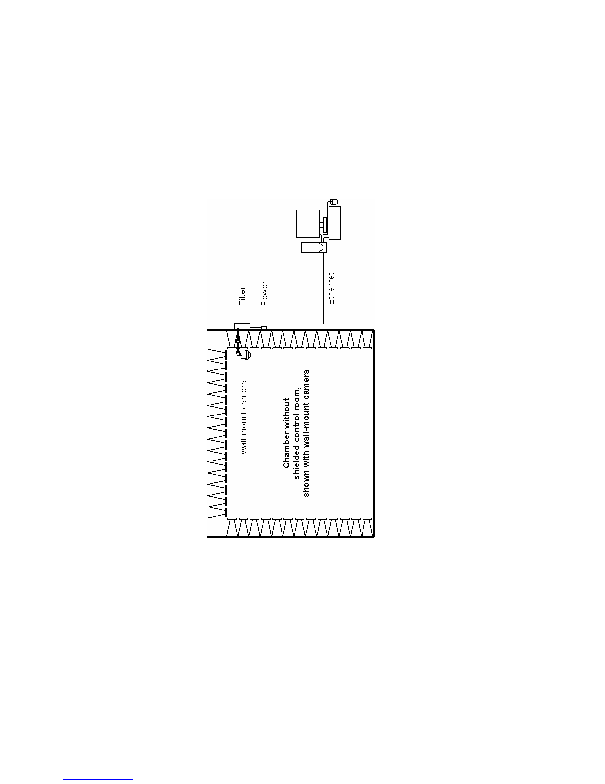
Standard Configuration and Components
The standard configuration for the Model 4340 CCTV is installed into a chamber
without a shielded control room.
See the diagram on the following page.
8 | Introduction

Introduction | 9
The standard configuration for the Model 4340 CCTV includes these
components:
Panasonic Network Camera WV-SC385—Includes Ethernet cable
and power cable connected to camera.
Shielded camera enclosure with dome—Includes camera
penetration connected to enclosure, and absorber wrap for the
enclosure.
Mounting hardware—The hardware allows you to mount the camera
enclosure from the wall or ceiling, and includes two 12-inch pipe
lengths, one 6-inch pipe length, one elbow joint (for wall mount only),
four pipe-to-pipe couplers, and absorber wrap for the assembled pipe.
10/100 Ethernet Filter—Provides one Ethernet connector, two
fiber optic connectors, an Ethernet-to-fiber optic converter, and a
fiber optic to Ethernet converter. Depending on your configuration, the
fiber optic to Ethernet converter may be provided as an internal or
external converter. Following are the two types of 10/100 Ethernet
filters:
–LMF-4095 10/100 Ethernet filter—Includes internal
fiber optic-to-Ethernet converter.
–LMF-4106 10/100 Ethernet filter—Includes external
fiber optic-to-Ethernet converter.
Personal Computer—Includes monitor, mouse, and keyboard.
10/100 Network Switch—If you ordered a multi-camera configuration,
you will install the 10/100 network switch. If you ordered a
single-camera configuration, you will not install the switch. In that case,
store the 10/100 network switch in a safe location for future expansion
of your Model 4340 CCTV.
A 30-meter Ethernet cable is included with some configurations.

10 | Introduction
Optional Configurations and Additional Components
Following are the optional configurations for the Model 4340 CCTV, including a
list of additional components required to install the configuration. For diagrams
and more information on installing an optional configuration, see Install Optional
Components on page 33.
IF YOU HAVE A CHAMBER WITH ASHIELDED CONTROL ROOM
You need these additional components:
Fiber optic-to-Ethernet converter
Ethernet cable to connect computer to converter (not included with all
configurations)
Fiber optic feedthrough connectors
30-meter fiber optic cable
3-meter fiber optic cable
IF YOU HAVE A TRIPOD MOUNT
For use with or without a shielded control room.
You need these additional components:
ETS-Lindgren H-491009 tripod
Battery pack and charger
Fiber optic-to-Ethernet converter
Ethernet cable to connect computer to converter (not included with all
configurations)
Fiber optic feedthrough connectors
30-meter fiber optic cable
3-meter fiber optic cable (only for installations with a shielded
control room)

Introduction | 11
IF YOU HAVE A MULTI-CAMERA SYSTEM
For use with or without a shielded control room.
You need these additional components:
The number of cameras in a multi-camera configuration may require
additional components other than those in the following list. Please
contact ETS-Lindgren to configure a multi-camera system.
For Use with
Shielded Control Room
For Use without
Shielded Control Room
10/100 Network switch
Fiber optic-to-Ethernet converter
per camera
Ethernet cable per converter—to
connect computer to network
switch, and network switch to each
fiber optic-to-Ethernet converter
Fiber optic feedthrough connectors
per camera
30-meter fiber optic cable per
camera
1-meter fiber optic cable per
converter
10/100 Network switch
Ethernet cables—to connect
computer to network switch
30-meter Ethernet cable per
camera
12 | Introduction
Power Supply Options
The 10/100 Ethernet filter provides the power for all configurations except the
tripod mount, which is powered by a battery pack.
10/100 ETHERNET FILTER
See the 10/100 Ethernet Filter
Installation Manual for all filter
information and installation
instructions. They are not included in
this document.
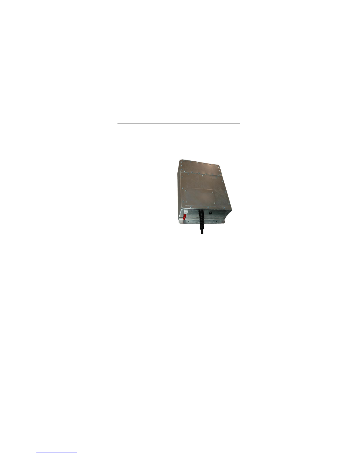
BATTERY PACK AND CHARGER
The tripod mount configuration is powered by a battery pack. The battery pack
contains a 12V 13Ah Nickel-Metal Hydride (NiMH) battery housed in a shielded
case. The battery normally provides up to 12 hours of operation, but operating
time may be reduced with extensive use of the pan and tilt and functions.
A battery charger and charger cable are included with the battery pack. See
Operating the Battery Pack on page 53 for more information.
Introduction | 13
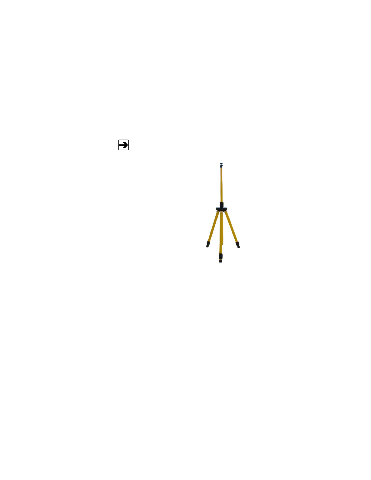
H-491009 Tripod
The H-491009 tripod includes a 1/4–20 thread center pole and a
3/8-inch thread center pole. Use the 3/8-inch thread center pole to
mount the camera onto the tripod.
This dielectric tripod is the preferred
method for mounting field probes for
making unperturbed field measurements. It
includes a 1/4–20 UNC threaded stud for
mounting any ETS-Lindgren probe with a
tripod mount. It is designed with an
adjustable center post and a rotating
mount.
About Installation and Setup
This manual provides instructions to install the Model 4340 CCTV into a chamber
without a shielded control room, including how to mount the camera on the wall,
from the ceiling, or on a tripod. Steps to install the optional components are also
included. For a list of optional configurations and components, see Optional
Configurations and Additional Components on page 10.
To install a configuration of the Model 4340 CCTV other than those described in
this manual, please contact ETS-Lindgren for more information.

14 | Introduction
INSTALLATION AND SETUP CHECKLIST
Complete pre-installation tasks—See page 23.
Install the 10/100 Ethernet filter—See page 25.
Mount the camera—For wall or ceiling mount, see page 29. For
tripod mount, see page 37.
Install optional items—See page 33.
Set up the computer—See page 47.
Operate the camera—See page 49.
ETS-Lindgren Product Information Bulletin
See the ETS-Lindgren Product Information Bulletin included with your shipment
for the following:
Warranty information
Safety, regulatory, and other product marking information
Steps to receive your shipment
Steps to return a component for service
ETS-Lindgren calibration service
ETS-Lindgren contact information
Maintenance | 15
2.0 Maintenance
Before performing any maintenance, follow the
safety information in the ETS-Lindgren
Product Information Bulletin included with your
shipment.
Maintenance of the Model 4340 CCTV is limited
to external components such as cables or
connectors.
Servicing or modifying the camera without
ETS-Lindgren authorization may void your
warranty.
There are no internal user serviceable items.
Only qualified personnel should service this
equipment. Contact ETS-Lindgren for service.
Do not remove the camera from the camera
enclosure. Do not attempt to disassemble the
camera.
See the manual provided with the computer for maintenance
recommendations.
If you have any questions concerning maintenance, contact ETS-Lindgren
Customer Service.
WARRANTY

16 | Maintenance
Replacement and Optional Parts
ETS-Lindgren may substitute a similar part or new part number with
the same functionality for another part/part number. Contact
ETS-Lindgren for questions about part numbers and ordering parts.
Following are the part numbers for ordering replacement or optional parts for the
Model 4340 CCTV.
Part Description
Part Number
DCCTV System, for use without shielded control
room—Includes computer, includes computer
monitor
4340-01
DCCTV System, for use without shielded control
room—Includes computer, does not include
computer monitor
4340-01XMON
DCCTV System, for use without shielded control
room—Does not include computer, does not
include computer monitor
4340-01XPC
DCCTV System for use with shielded control
room—Includes computer, includes computer
monitor
4340-02
DCCTV System for use with shielded control
room—Includes computer, does not include
computer monitor
4340-02XMON
DCCTV System for use with shielded control
room—Does not include computer, does not
include computer monitor
4340-02XPC
DCCTV System, Tripod Configuration, for use with
or without shielded control room—Includes
computer, includes computer monitor
4340-03
DCCTV System, Tripod Configuration, for use with
or without shielded control room—Includes
computer, does not include computer monitor
4340-03XMON

Maintenance | 17
Part Description
Part Number
DCCTV System, Tripod Configuration, for use with
or without shielded control room—Does not include
computer, does not include computer monitor
4340-03XPC
DCCTV Camera, Pan and Tilt
111095
LMF-4095 10/100 Ethernet Filter, for use without
shielded control room, includes internal
fiber optic-to-Ethernet converter
E-LMF-4095
LMF-4106 10/100 Ethernet Filter, for use with
shielded control room, includes external
fiber optic-to-Ethernet converter
E-LMF-4106
Computer, DCCTV Monitor and Controller
707033
Tripod
H-491009
Battery Pack, Enclosure, and Battery Charger
111589
Battery Pack only
400041
Battery Charger only
H-491198-120
10/100 Network Switch
707037
Fiber Optic-to-Ethernet Converter
708043
30-meter Ethernet Cable
675298
30-meter Fiber Optic Cable
705344-30
3-meter Fiber Optic Cable
705344-3
Fiber Optic Feedthrough Connector
708027
PSE Power Cord (Japan only)
670040
Service Procedures
For the steps to return a system or system component to ETS-Lindgren for
service, see the Product Information Bulletin included with your shipment.

18 | Maintenance
This page intentionally left blank.

Specifications | 19
3.0 Specifications
Camera Enclosure, Converter Enclosure, Dome
The converter enclosure is included only with a tripod configuration.
Enclosure/Dome Shielding:
Up to 200 Volts per meter (V/m)
Operating Temperature:
14°F to 104°F
(–10°C to 40°C)
Dome Dimensions
Height: 7.82 cm (3.08 in)
Radius: 7.82 cm (3.08 in)
Camera Enclosure Dimensions
Diameter: 16.57 cm (6.525 in)
Height: 9.685 cm (3.813 in)
Camera Enclosure Connectors:
Microphone
Line-out
Converter Enclosure Dimensions
Diameter: 21.9 cm (8.625 in)
Height: 6.35 cm (2.5 in)

20 | Specifications
Battery Pack and Charger
The battery pack and charger are included only with a
tripod configuration.
Battery Pack Dimensions:
Width: 12.7 cm (5.0 in)
Length: 25.4 cm (10.0 in)
Height (with handle):
17.18 cm (6.765 in)
Height (without handle):
12.28 cm (4.835 in)
Battery Type:
12V 13Ah Nickel-Metal
Hydride (NiMH), rechargeable
F battery pack, 13000 mAH
(rapid charge cells, 1.2 volts/cell)
Battery Life:
Up to 12 hours, depending on use
of pan and tilt functions
Battery Charger:
For 12V Nickel-Metal
Hydride (NiMH) batteries
Table of contents


