ETT ET-RS422/485 User manual

ETT CO.,LTD
-1-
www.etteam.com
ET-RS422/485 ISOLATION DIN
SPECIFICATIONS OF ET-RS422/485 ISOLATION DIN
1. CHIP ADM2587E is used as Line Driver to convert Signal ISOLATE
2. Baud Rate 115.2 kbps
3. Cable 4000 feet (1.2 km) in length
4. Change Signal RS232 to RS422 as Full Duplex by using 4-Wire
5. Change Signal RS232 to RS485 by using 2-Wire
6. Half Duplex Connection uses 2-Wire to be either Automatic or Handshake (RTS ON, RTS OFF)
7. Use RS232 Connector as DB9 Type.
8. LED displays state of running; green LED for receiving data (RX), yellow LED for transmitting data (TX), and red LED for
RS485
9. Be compatible with Voltage in the range of 9-24 VDC
10. Can install the box on Din rail

ETT CO.,LTD
-2-
www.etteam.com
COMPOSITION OF ET-RS422/485 ISOLATION DIN
1. Connector Voltage is compatible with voltage in the range of 9-24VDC.
2. Signals of Connector RS422/485 are listed below;
- TX(+) is Signal for transmitting data of RS422/485.
- TX(-) is Signal for transmitting data of RS422/485.
- RX(+) is Signal for receiving data of RS422/485.
- RX(-) is Signal for receiving data of RS422/485.
3. Jumper chooses Fail Safe Bias Resistance; it only enables the device at the origin and destination. There is Signal TZ, TL,
and TH on the side of transmitter and there is Signal RZ, RL, and RH on the side of receiver.
4. DIP Switch chooses format of connection as listed in the table below;
Mode
DIP1
DIP2
DIP3
DIP4
DIP5
DIP6
RS422 (FULL)
ON
ON
OFF
OFF
OFF
OFF
RS485-RTS OFF
OFF
OFF
ON
ON
OFF
OFF
RS485-RTS ON
OFF
OFF
ON
OFF
ON
OFF
RS485-AUTO
OFF
OFF
ON
OFF
OFF
ON
Table shows how to choose format of connection by DIP SWITCH.

ETT CO.,LTD
-3-
www.etteam.com
NOTE: When moving DIP Switch down, it becomes ON. Please look at the picture above, both DIP3 and DIP6 are in position
ON.
- RS422 (FULL) converts Signal RS232 to RS422.
- RS485-RTS OFF uses Signal from Pin RTS to control the alternation of receiver and transmitter. If Signal RTS is OFF, it
becomes transmitter; but if Signal RTS is ON, it becomes receiver instead.
- RS485-RTS ON uses Signal from Pin RTS to control the alternation of receiver and transmitter. If Signal RTS is ON, it
becomes transmitter; but if Signal RTS is OFF, it becomes receiver instead.
- RS485-AUTO uses circuit internal ET-RS422/485 ISOLATION DIN to check signal of transmitting data. If it transmits any
signal, the circuit will be transmitter; but if it does not transmit any signal, the circuit becomes receiver automatically.
5. It is Connector RS232 DB9 FEMALE and signals’name are shown in the table below;
Table shows details of PIN RS232.
PIN
NAME
DIR
DESCRIPTION
1
CD
IN
Carrier Detect
2
RXD
IN
Receive Data
3
TXD
OUT
Transmit Data
4
DTR
OUT
Data Terminal Ready
5
GND
-
Signal Ground
6
DSR
IN
Data Set Ready
7
RTS
OUT
Request To Send
8
CTS
IN
Clear To Send
9
RI
IN
Ring Indicator
ETT CO.,LTD
-4-
www.etteam.com
It shows position of PIN RS232.
6. LED displays state of running ET-RS422/485 ISOLATION DIN as listed below;
- PWR displays the state when supplied power to ET-RS422/485 ISOLATION DIN
- TX displays the state when transmitted data.
- 485 displays the state when transmitted data in the format of RS485
- RX displays the state when received data.
HOW TO CONNECT & USE
Connect ET-RS422/485 ISOLATION DIN to COM PORT of computer through Cable RS232 and another one side is
connected to Cable to connect to RS422/485 devices or may be connected to another one box (please read more information
in the next section). When using ET-RS422/485 ISOLATION, it requires connecting to Power Supply 9-24VDC.
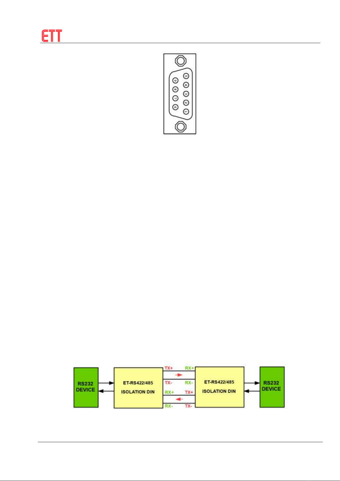
HOW TO CONNECT SIGNAL AS RS422
RS422Connection as Full Duplex: It transmits/receives data in both directions; it can transmit and receive data
simultaneously. Each set has 2 pairs of Cable (4-Wire); when it transmits-receives data, it looks like talking on the telephone.
Connect signal from the Circuit Receiver to the Circuit Transmitter of both sides. When transmitting-receiving data by this way,
it requires connecting to “Point-to-Point” device; it requires a device at the origin and another one device at the destination. The
reason why it uses this RS422 Connection is because it increases the distance for transmitting-receiving data longer without
modifying any program.
Picture shows how to connect Cable RS422 as Full Duplex.
ETT CO.,LTD
-5-
www.etteam.com
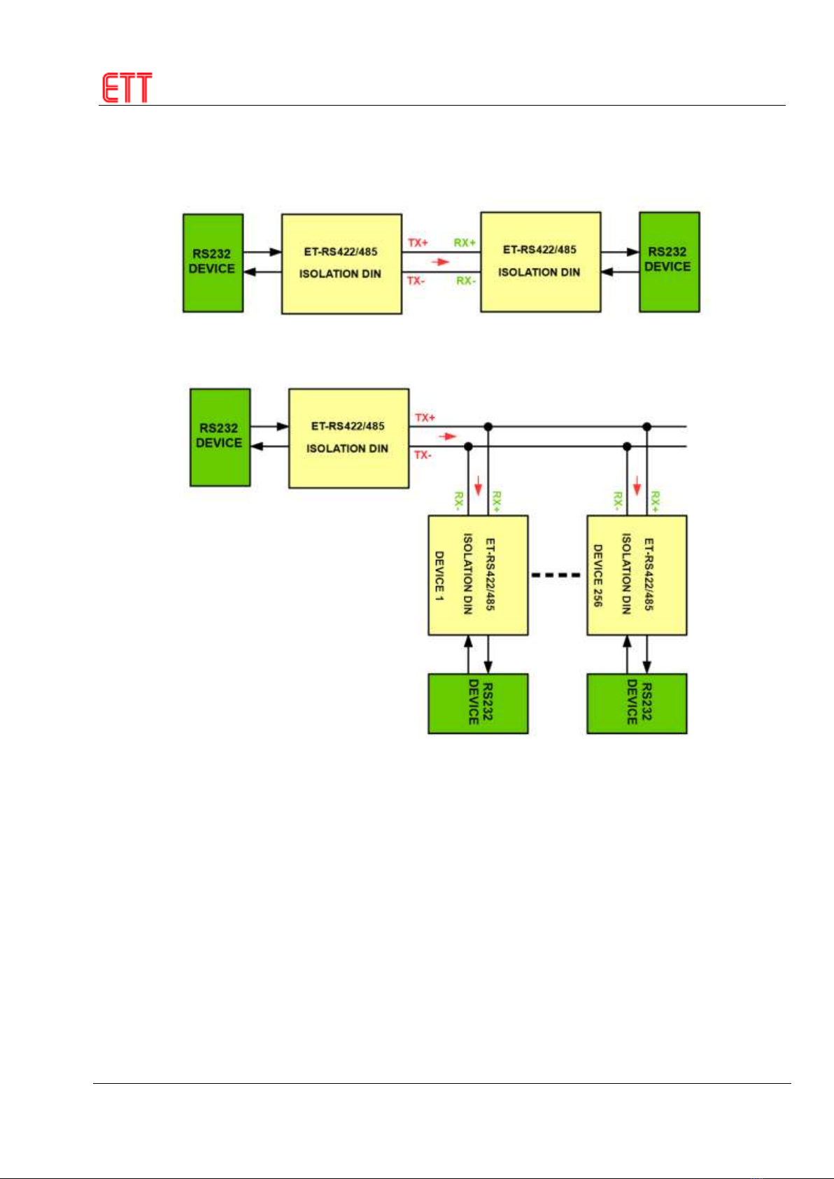
RS422 Connection as Simplex: It transmits-receives data in only one direction; its direction of communication is fixed either to
be receiver or transmitter only. When connecting signal in this way, it requires a pair of Cable (2-Wire). There is an advantage
of this connection type because it uses only one Circuit Transmitter but it can connect to 256 positions on the side of Circuit
Receiver; moreover, it uses a pair of Cable only.
Picture shows how to connect Cable RS422 as Simplex.
Picture shows how to connect Cable RS422 when receiving data from many devices simultaneously.
HOW TO CONNECT SIGNAL AS RS485
Connect whole system as Parallel: When connecting device in this way, it has to set priority of devices that are connected
together in the system. A device must be set as Master device, it will be an intermediate for transmitting-receiving all data, or it
may set order of transmitting-receiving data to other devices. For Slave devices, it must be set to receive data all the time first.
Master device scans each Slave device carefully to check if there is any data for transmitting; if yes, the Master device will
check where the destination is and it commands the specific device to receive the data directly. Next, the direction of Master
device will be changed to be receiver instead in order to set the Cable free (floated) and both devices is allowed to transmit
data. After both sides transmitted data completely, the Slave device must send Command to notify the Master device to know
that the transmission is complete and the Master device will scan the next Slave device.

ETT CO.,LTD
-6-
www.etteam.com
Picture shows how to connect Cable RS485 as Parallel.
Point-to-Point Connection: This way is to transmit-receive data between 2 devices by using a pair of Cable. Direction of both
devices must be controlled to be both receiver and transmitter. For communication, it has to set regulations of transmitting-
receiving data; both devices must alternate between transmitter and receiver, it cannot transmit-receive data simultaneously.
Picture shows how to connect Cable RS485 as Point-to-Point.
NOTE: When connecting signal as RS485, the side of TX and RX must be connected as parallel; so Fail Safe Bias Resistance
is also connected as parallel. In this case, it has to remove Jumper RZ, RL, RH or TZ, TL, TH and now there is only one Fail
Safe Bias Resistance.
Table of contents


