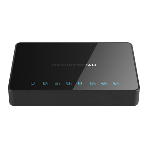
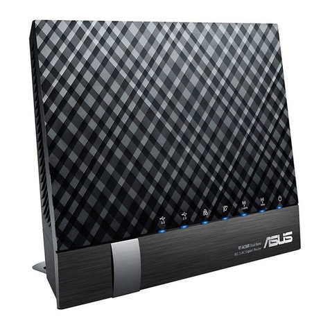
eTung PLC-505 User manual

PLC-505 PLC LianWangBao
User Manual
eTung Technology Co. Ltd
2nd Floor Building 3, Beike Industrial Park, No.7 Feng Xian Mid Road,
Haidian Dist. Beijing
TEL:4008-909-611 FAX:010-64857815
Website: www.etungtech.com.cn
Copyright © 2005-2018 ALL RIGHTS RESERVED

PLC-505 User Manual
2
This manual applies to the following models, and the corresponding
networks supported by the models are listed in the table below:
Model
Network
PLC-505-N4
4G/3G/2G (7 kinds of network modes) and WAN
cable networks, use 4G by default
PLC-505-W0
WIFI and WAN cable networks, use WAN by
default
PLC-505-W4
4G/3G/2G (7 kinds of network modes) and
WIFI/WAN cable networks, use 4G by default
PLC-505-N4G
4G/3G/2G (7 kinds of network modes) and WAN
cable networks, support GPS

PLC-505 User Manual
3
Table of Contents
1. Product Introduction .......................................................................................................4
1.1 Brief Introduction .........................................................................................................4
1.2 Product Outlook ............................................................................................................5
1.3 Standard Accessories..................................................................................................6
1.4 Dimension........................................................................................................................9
1.5 Working Mechanism ..................................................................................................10
1.6 Specifications ............................................................................................................... 11
1.6.1 Technical Parameters.................................................................................... 11
1.6.2 Indicator Light Description..........................................................................12
1.6.3 Serial Port Definition .....................................................................................13
1.6.4 RESET Button...................................................................................................14
1.7 Typical Usecases.........................................................................................................14
2. Device Configurations...................................................................................................17
2.1 Configurations..............................................................................................................17
2.1.1 Preparation........................................................................................................17
2.1.2 Configuring PLC-505 .....................................................................................17
2.2 Configuration Parameters .......................................................................................23
2.3 Restore to Default ......................................................................................................24
2.4 Firmware Update ........................................................................................................25
2.5 Remote Configurations.............................................................................................26
Appendix 1: Use PLC-505 Ethernet Functionality to Implement PLC Remote Data
Acquisition and Program Update ..............................................................................................31
Appendix 2: Use PLC-505 Serial Functionality to Implement PLC Remote Data
Acquisition and Program Update ..............................................................................................39
Appendix 3: Use PLC-505 to Access LAN Remotely via VPN .........................................46
Appendix 4: Configure PLC-505 to Access Internet via 4G Network .........................50
Appendix 5: Configure PLC-505 to Access Internet via Cable/WIFI...........................51
Appendix 6: Configure GPS Query Settings and GPS data format .............................59
Appendix 7: Send/Receive SMS with PLC-505‟s Ethernet Interface and SMS Format
..............................................................................................................................................................61
Appendix 8: Use VNC and PLC-505 to Access and Control Devices Remotely.......65

PLC-505 User Manual
4
1. Product Introduction
This chapter mainly introduces the outlook, accessories, specifications and
mechanism of PLC-505.
1. Brief Introduction
2. Product Outlook
3. Accessories
4. Dimension
5. Working Mechanism
6. Specifications
7. Typical Usecases
1.1 Brief Introduction
PLC-505 is an industrially designed product, and is especially used
with PLCs. PLC-505 provides program download and data acquisition
functionalities for PLCs that have RJ-45 Ethernet interface, or
RS232/RS485 serial interfaces. It supports PLCs from Siemens,
Mitsubishi, Omron, Panasonic, Delta, Fatek, etc. PLC-505 connects
with 4G network, and with PLC programming tools or SCADA software
to implement remote program download and data acquisition.
PLC-505 integrates functionalities of all other PLC LianWangBao
products. It not only supports all network modes from China‟s three
mobile operators, but also has two RJ-45 Ethernet interfaces, one of
which (LAN1) can be used as WAN as well, one RS232 and one RS485
serial interfaces. Ethernet interfaces and serial interfaces can be used
at the same time. It breaks through network limits, so that it not only
supports 4G network, but also 3G: TD-SCDMA/WCDMA/EVDO or 2G:
GPRS/EDGE/GSM/CDMA networks, and can automatically switch
between different networks. In case there is no 4G network or SIM
card does not support 4G, PLC-505 can automatically switch to 3G or
2G networks.
PLC-505 has WIFI functionality as well, and supports 802.11b/g/n
protocol. In theory the highest speed can be 150Mbps. Either mobile
phones, PCs or other devices that has WIFI functionality, can bind

PLC-505 User Manual
5
PLC-505‟s WIFI access point and share Internet access via PLC-505.
This greatly extends the number of devices that can connect with
PLC-505 at the same time.
PLC-505 can use WAN or WIFI network: in case cable network is
available, WAN (LAN1) port can be used to access cable network; and
in case WIFI is available, PLC-505 can be configured to access internet
via WIFI. 4G, WAN and WIFI are all supported by PLC-505, this greatly
facilitates customer‟s project deployment that customers do not have
to choose different devices from different suppliers because of
different network access at the spot. This can not only save
procurement cost, but also reduce maintenance effort for the projects.
GPS model can be embedded into PLC-505, to implement device
location. Set time interval of transmitting GPS location data, then after
PLC-505 connects to data center, it will transmit location data to data
center with the predefined time interval. Data center can also ask for
GPS location data at any time by sending commands. Besides, the
device connecting PLC-505 can also send AT command via
RS232/RS485 serial port to ask for location information.
PLC-505 is easy to use, and is plug-n-play without any configuration.
Together with eTung‟s eYun platform and Virhub/Vircom software, it
can be easy to integrate with PLC programming software, and there is
no extra integration effort. PLC-505 is stable and easy-to-use, thus
greatly facilitates project deployment.
1.2 Product Outlook

PLC-505 User Manual
6
Figure 1-1: PLC-505 side view 1
Figure 1-2: PLC-505 side view 2
1.3 Standard Accessories
Figure 1-3: 4G all frequency sucking antenna

PLC-505 User Manual
7
Figure 1-4: WIFI antenna
Figure 1-5: GPS antenna

PLC-505 User Manual
8
Figure 1-6: Cross cable
NOTE: The accessories may be different because of different models and
customer requirements, the figures above are just for reference.

PLC-505 User Manual
9
1.4 Dimension
Figure 1-7: PLC-505 dimension
Figure 1-8: Installation effect

PLC-505 User Manual
10
1.5 Working Mechanism
Figure 1-9: PLC-505 working mechanism
PLC-505 has RJ45 Ethernet interface and RS232/RS485 serial
interface, so it can connect with PLCs that have Ethernet interface or
serial interface, and Ethernet and serial interfaces can be used at the
same time.
1. Usage of Ethernet interface
PLC-505 connects with PLC via Ethernet cross cable, and after
power on, it dials up into 3G/4G network (or, via cable/WIFI
network) and access Internet, then establishes connection with
cloud platform and mServer. Use browser at the host computer to
access IoT cloud platform, and monitor PLC‟s data in real time. At
the same time Virhub software is run at the host computer and
connects to mServer as well. Then with Virhub functionality PLC and
the host computer are in the same virtual LAN, and user software at
the host computer can then access PLC, to download or update
program.
PLC-505 has two RJ45 interfaces, and can be WIFI AP. So it allows
multiple PLCs (or other devices) that have Ethernet interface to
connect with it. And with PLC-505‟s virtual channels, one PLC-505
can serve at most nine PLCs to perform remote data acquisition and

PLC-505 User Manual
11
program update.
2. Usage of serial interface
PLC-505 connects PLC with RS232 (or RS485) serial port. After power
on it dials up into 3G/4G network (or, via cable/WIFI) and access
Internet, then establishes connection with cloud platform and
mServer. Use browser at the host computer to access IoT cloud
platform, and monitor PLC‟s data in real time. At the same time Vircom
is run at the host computer and connects to mServer as well, then user
software at the host computer can use the virtual serial port from
Vircom to implement bi-directional communication with PLC.
PLC-505 has one RS232 ad one RS4845 serial port, and support
virtual channels on RS485 serial port. One PLC-505 can serve at most
five PLCs (or other devices) with RS485 serial port to perform remote
data acquisition and program update.
1.6 Specifications
1.6.1 Technical Parameters
Basic Parameters
Power Supply: +12 ~ +48V wide range of voltage input
Power Connector: inner(+) outer(-)
Max Current: 350mA@+12V DC
Standby Current: 250mA@+12V DC
Network:
PLC-505-N4:
FDD-LTE/TDD-LTE
TD-SCDMA/DC-HSPA+/HSPA+/UMTS
EVDO/EDGE/GPRS/GSM/CDMA/WAN
PLC-505-W0:WIFI/WAN
PLC-505-W4:
FDD-LTE/TDD-LTE
TD-SCDMA/DC-HSPA+/HSPA+/UMTS
EVDO/EDGE/GPRS/GSM/CDMA
WIFI/WAN
PLC-505-N4G:
FDD-LTE/TDD-LTE
TD-SCDMA/DC-HSPA+/HSPA+/UMTS
EVDO/EDGE/GPRS/GSM/CDMA/WAN

PLC-505 User Manual
12
GPS
Frequency:
Three-Band FDD-LTE B1/B3/B8
Four-Band TDD-LTE B38/B39/B40/B41
Dual-Band UMTS/HSDPA/HSPA+ B1/B8
Dual-Band TD-SCDMA B34/B39
Single-Band CDMA1X/EVDO BC0
Dual-Band GSM/GPRS/EDGE 900/1800MHz
WIFI IEEE 802.11n/g/b: 2.4GHz
GPS L1, 1575.42MHz
Data Interface: RS232/RS485, two RJ45 Ethernet interfaces
Temperature: -30ºC ~ +80ºC
Humidity: 95%@+40ºC
Dimension: 88x118x34mm (excluding antenna and handle)
Basic Functions
Support NAT
Support DHCP server
Support DNS Proxy
Support port forwarding
Support DMZ host(IP address mapping)
Support VPN
Support dynamic domain auto-registration
Support configuring static route table
Support real-time speed display of wireless network
Support configuring with serial port, telnet and web
interface
Support serial port DTU function, Ethernet and serial
interfaces can be used at the same time
Support agent client
1.6.2 Indicator Light Description
LED
Indicato
r Light
Color
Status
Description
Signal
lights
Orange
Always light
There are three signal lights.
All lights one means the signal
is strongest.
PWR
Red
Always light
Device is working
Extinguished
Device is not working
NET
Green
Always light
Connected to Internet
Extinguished
No connection to Internet

PLC-505 User Manual
13
ERR
Red
Always light
3G/4G model is not working or
SIM card error
Extinguished
3G/4G model is working
SVR1
Green
Always light
DTU has connected to data
center
Extinguished
DTU does not connect to data
center
SVR2
Green
Always light
Connection to mServer is
established.
Extinguished
Connection to mServer is not
established.
WIFI
Green
Always light
WIFI is enabled
Extinguished
WIFI is not enabled
LAN1
(WAN)
Green
Always light
Ethernet connection OK
Extinguished
Ethernet connection not OK
LAN2
Green
Always light
Ethernet connection OK
Extinguished
Ethernet connection not OK
GPS
Green
Always light
Has latitude and longitude
data
Flashing quickly
Found satellite signal, but has
no latitude and longitude data
Flashing slowly
No satellite signal
Table 1-1 PLC-505 indicator light description
1.6.3 Serial Port Definition
Type
RS-232
Pin
2
3
5
Definition
RXD
TXD
GND
Table 1-2: PLC-505 RS232 serial port
(Standard RS-232 DB9 male port) pin definition
Type
RS-485
Pin
485A
485B
GND
Definition
A
B
GND
Table 1-3: PLC-505 RS485 serial port pin definition

PLC-505 User Manual
14
1.6.4 RESET Button
To reset PLC-505 to default, login its configuration web page, and
choose “System tools” -> “Restore set”; Or: press the RESET button
continuously, the signal lights will flash one by one, until all lights are
on, that means the reset is finished.
1.7 Typical Usecases
Figure 1-10: Implement PLC remote monitoring and program update via
PLC-505‟s Ethernet functionality

PLC-505 User Manual
15
Figure 1-11: Implement PLC remote monitoring and program update via
PLC-505‟s serial functionality
Figure 1-12: Implement remote control of touchscreen desktop via PLC-505‟s
agent client functionality and VNC software

PLC-505 User Manual
16
Figure 1-13: Use PLC-505 to access LAN remotely via VPN

PLC-505 User Manual
17
2. Device Configurations
This chapter introduces how to use PLC-505 and related parameters.
1. Configurations
2. Parameters
3. Restore to default
4. Firmware Update
5. Remote Configurations
2.1 Configurations
2.1.1 Preparation
One cross Ethernet cable used to connect PLC-505 with PC or
customer device;
One 4G all frequency sucking antenna;
One power supply;
One USIM card that can access internet.
2.1.2 Configuring PLC-505
Connect PLC-505 with PC via a cross Ethernet cable;
Boot PC, and set IP address as "Automatically obtain IP
address";

PLC-505 User Manual
18

PLC-505 User Manual
19
Figure 2-1: Set IP address as "Automatically obtain IP address"
Open IE browser, input address "http://192.168.10.1" and
press Enter;
Input "root" as username and "1234" as password, then press
Enter to login web configuration interface and configure the
device.
Figure 2-2: Login router configuration interface

PLC-505 User Manual
20
It is clear to see each configuration item in the router
configuration interface. To change some parameter, click it,
modify and then save it, then reboot the router.
To use Ethernet functionality, click “ConnBOX”-> “Ethernet”.
By default, cloud platform domain and port are
dsc.thinglinx.com and 20001, mServer domain and port are
3g.etungtech.com and 8080, and normally keep the default
settings. Then configure PLC with Ethernet interface. PLC-505
supports multiple channels; each channel can be assigned to
one PLC (or other device). PLC-505 supports at most ten
channels, and each channel has a channel ID. The channel ID is
derived from PLC-505‟s IMEI labeled on its shell. For example,
PC-505‟s IMEI is 240305001234567, then Ethernet channel‟s
ID is 2403050X1234567, and X can be 0~9. The first channel‟s
ID is 240305001234567, and this channel is fixed to connect
mServer only and not to connect cloud platform, and enable
virhub functionality. This channel is designed only for PLC
program update, and it can also be used to perform PLC-505‟s
remote configuration. The other nine channels are used to
connect PLC or other device with Ethernet interfaces.
Customers can choose the channels flexibly. For each channel,
configure PLC IP as the device‟s Ethernet IP, and PLC port as the
device‟s listening port, then tick “Enable”, press Save and
reboot PLC-505.
Table of contents
Other eTung Network Router manuals
