Operating Instructions
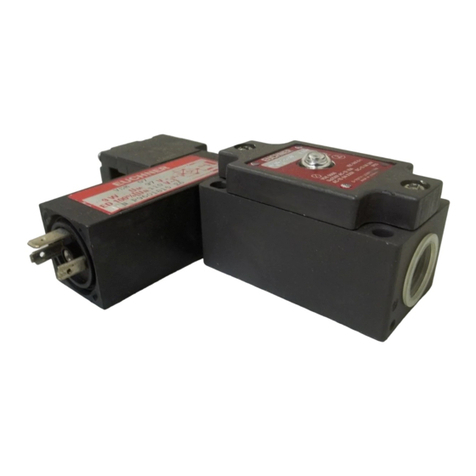
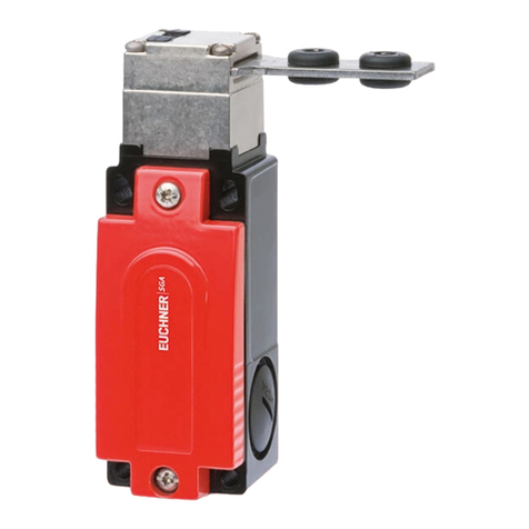
Transponder-Coded Safety Switch CTM-L2-AS1B
2(translation of the original operating instructions) 2539116-02-09/21
Contents
1. About this document............................................................................................. 4
1.1. Scope............................................................................................................................................4
1.2. Target group ..................................................................................................................................4
1.3. Key to symbols...............................................................................................................................4
1.4. Supplementary documents ..............................................................................................................4
2. Correct use .......................................................................................................... 5
3. Description of the safety function .......................................................................... 6
4. Exclusion of liability and warranty ......................................................................... 7
5. General safety precautions ................................................................................... 7
6. Function............................................................................................................... 8
6.1. Guard locking on version CTM-L2.....................................................................................................8
6.2. Switching states .............................................................................................................................9
7. Manual release................................................................................................... 10
7.1. Auxiliary release............................................................................................................................10
7.1.1. Actuating auxiliary release .............................................................................................10
8. Mounting............................................................................................................ 11
9. Electrical connection .......................................................................................... 12
9.1. Notes about .........................................................................................................................12
9.2. Setting the AS-Interface address ....................................................................................................12
9.3. Conguration in the AS-Interface safety monitor ..............................................................................12
9.3.1. Dual-channel conditionally dependent..............................................................................12
9.4. AS-Interface status messages........................................................................................................13
9.5. Safety in case of faults..................................................................................................................13
9.6. Connection of guard locking control ...............................................................................................13
9.6.1. Guard locking control by means of switching the auxiliary voltage.....................................13
9.6.2. Guard locking control via ASi bit D0 (guard locking for process protection only) .................13
10. Setup ................................................................................................................. 14
10.1. LED displays ................................................................................................................................14
10.2. Teach-in function for actuator (only for unicode evaluation) ...............................................................14
10.2.1. Actuator teach-in...........................................................................................................14
10.3. Functional check...........................................................................................................................15
10.3.1. Mechanical function test ................................................................................................15
10.3.2. Electrical function test...................................................................................................15
11. System status table ............................................................................................ 16
