3
2525462-03-06/21 (translation of the original operating instructions)
Operating Instructions
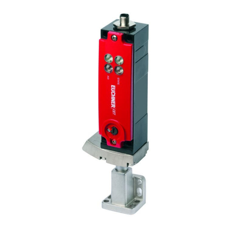
Transponder-Coded Safety Switch CTM-LBI-BP/BR
EN
9.7. Connector assignment of safety switch CTM-…-BP-…-SA-166087/166088
with plug connector M12, 8-pin......................................................................................................17
9.8. Connector assignment of safety switch CTM-…-BR-…-SA-…
with plug connector M12, 8-pin......................................................................................................17
9.9. Connector assignment of safety switch CTM-…-BR-…-AZD-SA-…
with plug connector M12, 8-pin......................................................................................................17
9.10. Connector assignment of safety switch CTM-…-BR-…-SP-…
with plug connector M12, 12-pin....................................................................................................18
9.11. Connection without and with IO-Link communication.........................................................................18
9.11.1. Connection without IO-Link communication......................................................................18
9.11.2. Connection with IO-Link communication...........................................................................18
9.12. Connector assignment of Y-distributor for series connection without IO-Link communication ...............19
9.13. Connector assignment of Y-distributor for series connection with IO-Link communication....................20
9.14. Connection of a single CTM-BP/BR (separate operation) ..................................................................21
9.15. Connection of several devices in a switch chain (series connection)..................................................23
10. Using communication data.................................................................................. 26
10.1. Connection to a BR/IO-Link Gateway GWY-CB..................................................................................26
10.2. Connection to a safety relay ESM-CB..............................................................................................26
10.3. Overview of the communication data ..............................................................................................26
10.3.1. Cyclical data (process data)...........................................................................................26
10.3.2. Acyclical data (device data and events)...........................................................................27
10.4. Notes on operation with safe control systems.................................................................................28
11. Setup ................................................................................................................. 29
11.1. LED displays ................................................................................................................................29
11.2. Teach-in function for actuator (only for unicode evaluation) ...............................................................29
11.2.1. Actuator teach-in...........................................................................................................29
11.3. Functional check...........................................................................................................................30
11.3.1. Mechanical function test ................................................................................................30
11.3.2. Electrical function test...................................................................................................30
11.4. Factory reset................................................................................................................................30
12. System status table ............................................................................................ 31
13. Technical data .................................................................................................... 33
13.1. Technical data for safety switch CTM-LBI ........................................................................................33
13.1.1. Typical system times.....................................................................................................34
13.2. Radio frequency approvals.............................................................................................................35
13.3. Dimension drawing for safety switch CTM… ...................................................................................36
13.4. Technical data for actuator A-B-A1-A1-….........................................................................................37
13.4.1. Dimension drawing for actuator A-B-A1-A1-… ..................................................................37
14. Ordering information and accessories................................................................. 38
15. Inspection and service ........................................................................................ 38
16. Service .............................................................................................................. 38
17. Declaration of conformity ................................................................................... 39
