EUCOL U9036 User manual

OPERATION MANUAL
U9036 Motor Stator Tester
EUCOL ELECTRONIC TECHNOLOGY CO.,LTD.
23-B2 Bulding,No.1,North Qingyang Road,Changzhou,China
Tel:+86-519-85505199 Fax: +86-519-85505169
Http://www.eucol.com.cn

U9036 Operation Manual Contents
Contents
Chapter 1 Overview ............................................................................................................................ 1
1.1 Introduction .......................................................................................................................... 2
1.2 Principles of IW(Surge) ......................................................................................................... 2
1.3 Operation environment ........................................................................................................ 3
1.3.1 Power supply .............................................................................................................. 3
1.3.2 Environment temperature and humidity ................................................................... 3
1.3.3 Warm-up .................................................................................................................... 3
1.4 Dimensions and weight ........................................................................................................ 3
Chapter 2 General specifications ........................................................................................................ 4
2.1 Specifications ........................................................................................................................ 4
2.2 Other specifications .............................................................................................................. 5
Chapter 3 Panels and display .............................................................................................................. 6
3.1 Front panel ........................................................................................................................... 6
3.2 Rear panel ............................................................................................................................. 8
Chapter 4 Instruction for Use .............................................................................................................. 9
4.1 Test setup.............................................................................................................................. 9
4.1.1 DCR Setup .................................................................................................................. 9
4.1.2 L(Inductance) Setup ................................................................................................. 12
4.1.3 IW (Surge) setup ...................................................................................................... 14
4.1.4 Insulation Resistance (IR) setup ............................................................................... 21
4.1.5 HIPOT setup ............................................................................................................. 22
4.1.6 DCR BAL Setup ......................................................................................................... 24
4.1.7 L BAL Setup .............................................................................................................. 25
4.1.8 IW Balance Setup ..................................................................................................... 26
4.1.9 Open/Short(O/S) setup ............................................................................................ 26
4.1.10 Seq Setup ............................................................................................................... 27
4.2 System Setup ...................................................................................................................... 28
4.2.1 System Config ........................................................................................................... 28
4.2.2 Test Config ................................................................................................................ 30
4.2.3 Firmware Upgrade ................................................................................................... 32
4.2.4 HV Test ..................................................................................................................... 32
4.3 File List ................................................................................................................................ 33
4.4 How to test ......................................................................................................................... 34
4.4.1 Start testing .............................................................................................................. 34
4.4.2 Judgment result analysis .......................................................................................... 37

U9036 Operation Manual Contents
4.4.3 View history data ..................................................................................................... 38
Chapter 5 Remote control ................................................................................................................. 39
5.1 Instruction of RS232C interface .......................................................................................... 39
5.1.1 The connection of the instrument with PC .............................................................. 39
5.1.2 Main parameters for serial port ............................................................................... 40
5.2 Instruction of USBCDC interface (virtual serial port) .......................................................... 40
5.3 Instruction of USB TMC interface ....................................................................................... 41
Chapter 6 Handler interface ............................................................................................................. 43
6.1 Basic information ................................................................................................................ 43
6.2 Electrical characteristics ..................................................................................................... 44
6.2.1 DC isolated output ................................................................................................... 44
6.2.2 Isolated input ........................................................................................................... 46
6.3 Jumper setup on HANDLER interface ................................................................................. 48
Chapter 7 Package contents and warranty ....................................................................................... 49
7.1 Package contents ................................................................................................................ 49
7.2 Warranty ............................................................................................................................. 49

U9036 Operation Manual Chapter 1 Overview
1
Chapter 1 Overview
Thank you for using our products. Before using, please verify that you have received all the
items listed in the last chapter and any optional accessories you may have ordered. If anyone is
missing, please contact us without delay.
For your proper use of U9036, please read this manual carefully.
Warning!
1) Operation
Do not put heavy objects on the tester.
There is a cooling fan on the rear panel of this instrument, so any block of the air inlet is
prohibited.
2) Rigid power input
The stability of high voltage depends on stable power input. Make sure to provide rated
AC power or corrected power.
3) Grounding
For the safety of personnel and instrument, ensure the grounding terminal, designed in
power cord, be grounded correctly.
4) Test cable
When testing, the cable and test samples connected will carry a high voltage. To avoid
electrical shock hazard, do not touch test terminals and test samples.
5) DO NOT open the case unauthorized
To avoid the injury to personnel and damage to the instrument, do not open the case
unauthorized due to the existence of high voltage in instrument.
6) Carry or move
Before moving the instrument, unplug the AC power sockets and remove high voltage test
line or external control line.
7) Maintenance
When not used, the instrument should be covered with a plastic or cloth cover. Do not
use the following chemicals to clean the instrument: diluent, benzene or organic solvent
with similar chemical property with above materials. To clean the tester, wipe the dirty
parts with a soft cloth socked with neutral detergent.
8) Location
Do not locate the instrument in the environment of high temperature, direct sunlight or
poor ventilation. In addition, the instrument will generate high voltage, so it must be used
at room temperature and in the absence of much dust.

U9036 Operation Manual Chapter 1 Overview
2
Lx
Vdc C1 C2 Rx
SW
DUT
Vo(t)
1.1 Introduction
U9036 is specially designed for motor stators to test the DC resistance, Inductance, Insulation
resistance, inter-IW(Surge) circuit and AC/DC withstanding. U9036 is equipped with 12
independent test channels and 1 high voltage return terminal.
Adopting advanced IW(Surge) test technology, U9036 compares standard waveform stored in
the non-volatile memory with the current tested waveform and provides the comparison result
according to AREA SIZE, DIFFERENTIAL AREA, CORONA DISCHARGE or DIFFERENTIAL PHASE.
With its strong functions, accurate test, flexible operation method and multiple interfaces,
U9036 can provide a test solution for most motor stator products.
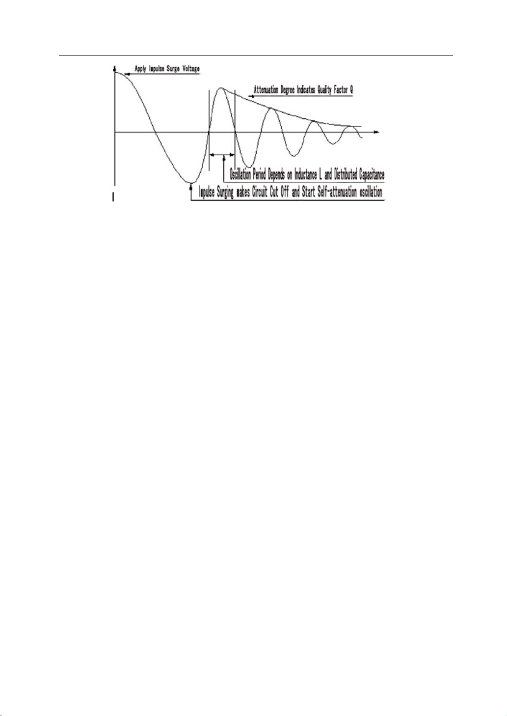
1.2 Principles of IW(Surge)
The IW(Surge) test can test the electrical characteristics of coil winding without damaging the DUT.
The prerequisite condition is to judge the quality of coil winding in transient moment. The
detection is carried out when the same electric impulse, as used in the standard coil and here
discharged by a capacitor, is applied to the DUT. The voltage attenuation wave is generated in
response to the impulse, related to the Q-factor and inductance of the coil. In this sense, the
tester can detect turn and IW(Surge), the differences in the number of turns and the material of
the core. If high impulse voltage is applied, the poor insulation will appear as a corona or layer
discharge.
Figure 1-1 Simplified diagram for principles of winding IW(Surge)
In figure 1-2, the self-oscillation attenuation wave has a close relation with the inductance L and
quality factor Q, while L and Q depend on the number of turn, manufacture technology,
properties of iron core material and whether it has air-coils. What’s more, the applied voltage is
a high impulse voltage, thus, it is easy to observe the short circuit, partial short turns and lays or
turns discharge phenomenon caused by insulation damage.
U9036 Operation Manual Chapter 1 Overview
3
Figure 1-2 Typical self-attenuation oscillation wave
1.3 Operation environment
1.3.1 Power supply
Voltage: 198V-242V AC or 99V - 121V
Power frequency: 47.5Hz-52.5Hz
Consumption: ≤200VA
1.3.2 Environment temperature and humidity
Normal working temperature: 0℃~40℃, Humidity: ≤ 90%RH
Referential working temperature: 20℃±8℃, Humidity: ≤ 80%RH
Transferring environment temperature: 0℃~50℃, Humidity: ≤ 93%RH
1.3.3 Warm-up
The warm-up time should not be less than 15 minutes.
1.4 Dimensions and weight
Dimensions (W*H*D): 430mm×175mm×440mm
Weight: Approx. 26.0kg
U9036 Operation Manual Chapter 2 General specifications
4
Chapter 2 General specifications
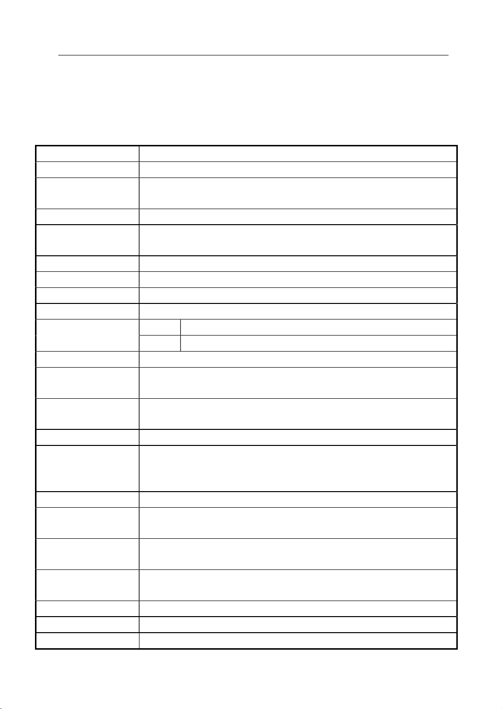
2.1 Specifications
DC Resistance
Measurement range 0.1mΩ~20kΩ (4-wire measurement accuracy)
Measurement
accuracy
0.1mΩ~200mΩ ±(0.1% ± 0.5mΩ)
200mΩ~20kΩ ±0.1%
Inductacne
Measurement
Parameters
Ls,Lp,Q
Test frequency 50Hz,60Hz,100Hz,120Hz,1kHz,10kHz,20kHz,40kHz,50kHz,100kHz
Test Levels 0.1V,0.3V,1.0V
Output Impedance 100Ω
Basic Accuracy 0.1%
Measurement Ranges
L 0.001uH ~ 9.9999kH
Q 0.0001-999.99
Insulation Resistance
Output Voltage Range
100V ~ 1.000kV
±(1.5% of reading + 5 counts),Resolution: 2V
Resistance
Measurement Range
1MΩ ~ 10GΩ
Test Time 0.3S ~ 999.9S
Accuracy <500V 1 MΩ
∼
1GΩ: ± (10% of reading + 5 counts)
>=500V 1 MΩ
∼
1GΩ: ± (5% of reading + 5 counts)
1GΩ
∼
10 GΩ: ± (10% of reading + 5 counts)
AC/DC Withstanding
Output Voltage Range
AC:0.050kV
∼
5.000kV(±2% of reading+5 digits)
DC:0.050kV
∼
6.000kV(±2% of reading+5 digits)
Current Measurement
Reange
AC:0~30mA
DC:0~10mA
ARC Detect AC:1mA ~ 15mA
DC:1mA ~ 10mA
Test Time 0.3s~999.9s
Accuracy ±2%

U9036 Operation Manual Chapter 2 General specifications
5
Impulse Winding Test(Surge test)
Measurement voltage
100V~5000V, 10Vsteps, ±5%±10V
Measurement item AreaSize Comparison, DiffZone Comparison, Corona Comparison,
PhaseDiff Comparison, Waveform Comparison
Measurement
repeatability accuracy
1%
Waveform sampling Sampling rate: 100MSa/s~100kSa/s,10 bins
Resolution ratio: 8bits
Sampling point: 6500bytes
Input impedance 10MΩ
2.2 Other specifications
Test Channels 4 ~ 12(Customization)
Judgment output PASS/FAIL display, LED display, beeper alarm
Beep mode High long, low long, single-short, double-short, OFF
Data recording 1000 groups of test data
Memory
Internal 180 groups(standard waveform data and test setup parameters)
U-disk 600 groups(standard waveform data and test setup parameters)
Interface HANDLER (START,STOP,PASS,FAIL,EOM)
USB Slave, RS232C
USB Host (storage of BMP, GIF, PNG and CSV files, support firmware
upgrade)

U9036 Operation Manual Chapter 3 Panels and display
6
Chapter 3 Panels and display
3.1 Front panel
No. Name Description
1 POWER Switch on or off the main power.
2 START key Press the key to start a measurement.
3 STOP key In the process of test, pressing the key to
terminate the measurement.
4 Brand and model Brand and model.
5 LCD screen 7.0-inch 800×480 dot-matrix TFT LCD displays
measurement waveform, set parameters, system
configurations, etc.
6 Return key Currently used for searching file in <File List>
page
7 SOFTKEY The functions of the six soft keys are not fixed
and have different functions in different menus.
The corresponding function of each soft key is
displayed along its right side.
8 [FILE] key Press FILE menu key to enter the <File List>
page.
9 [MEAS] key Press MEAS menu key to enter the <Test Disp>
page.

U9036 Operation Manual Chapter 3 Panels and display
7
10 CURSOR Control the movement of highlight bar in LCD
parameter area. The selected parameter region
will be highlighted.
11 [SETUP] key Press SETUP menu key to enter the <Test Setup>
page.
12 [SYSTEM] key Press SYSTEM menu key to enter the <SYSTEM>
page.
13 Unit key Input the unit of data
14 Numeric key Input numbers or characters.
15 BACKSPACE key Delete numbers or characters wrongly entered.
16 ESC key ESC key is used to cancel inputting.
17 USB interface Be used for connecting the U-disk.
18 ENTER key Confirm the numbers or characters entered.
19 SAVE key Press SAVE key to save the image files (BMP, GIF
and PNG) or wave files (CSV) to U-disk.
20 LOCK/LOCAL key Press LOCK key, the key will be lightened and the
panel keys are locked; press LOCK again, the key
will not be lightened and the panel keys are
unlocked. In remote control, press this key to
unlock the remote control state and return to
key operation.
21 PASS/FAIL indicator Output the judgment results after one
measurement.
22 High Voltage indicator(DANGER) The indicator will be lightened when high
voltage is output on the test terminals.
23 Output low terminal of withstand
voltage & insulation test
(RT/LOW)
Connect the DUT.
24 Channel indicator Indicates the current test channel.
25 [L/DCR] key Press this key to enter <L Setup> or <DCR Setup>
page
26 [IR/IWT] key Press this key to enter <IR Setup> or <IW(Surge)
Setup> page
27 [AC/DC] key Press this key to enter <Hipot Setup> page
28 Measurement signal output
terminal (CH1~CH12)
Connect the DUT.
Table 3-1 Front panel instruction
U9036 Operation Manual Chapter 3 Panels and display
8
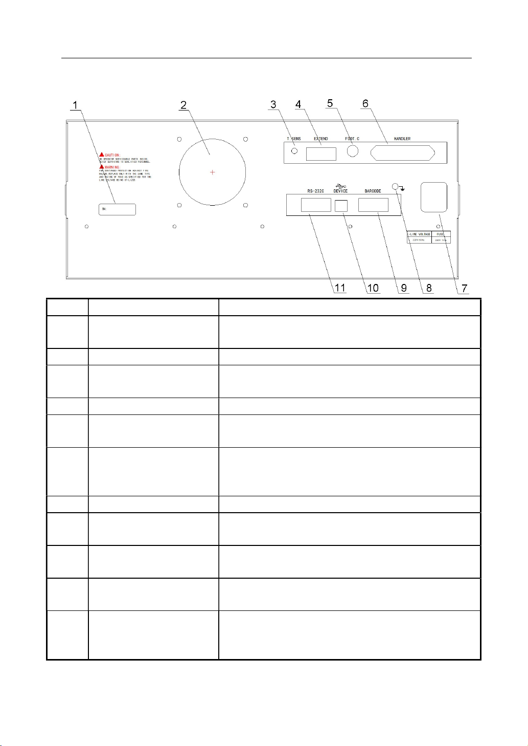
3.2 Rear panel
No. Name Description
1 Name plate Record the information of manufacture date, model,
batch number, etc.
2 Fan window Thermal discharge.
3 Temperature Sensor socket
Connect the temperature sensor to test the environment
temperature.
4 Extension interface Reserved interface
5 FOOT CONTROL In MAN mode, the foot switch can be used to start a
measurement.
6 HANDLER interface Comparison results are output via the handler interface.
The instrument can get START or STOP signal through the
interface.
7 3-wire power socket Connect the AC power.
8 Ground terminal Safety ground terminal. Connect the other terminal to
ground for the safety of operator.
9 Barcode interface Connect the barcode scan gun to input bar code and
other information.
10 USB communication
interface
Support USB TMC and USD CDC, the function is the same
as 6.
11 RS232C serial interface The serial communication interface can be connected to
an external device for remote control without panel
operation.
Table 3-2 Rear Panel Instruction
U9036 Operation Manual Chapter 4 Instruction for Use
9
Chapter 4 Instruction for Use
This chapter introduces the operation of different keys and rotary knob, including the
measurement display page, measurement setup page, system setup page and file manage page.
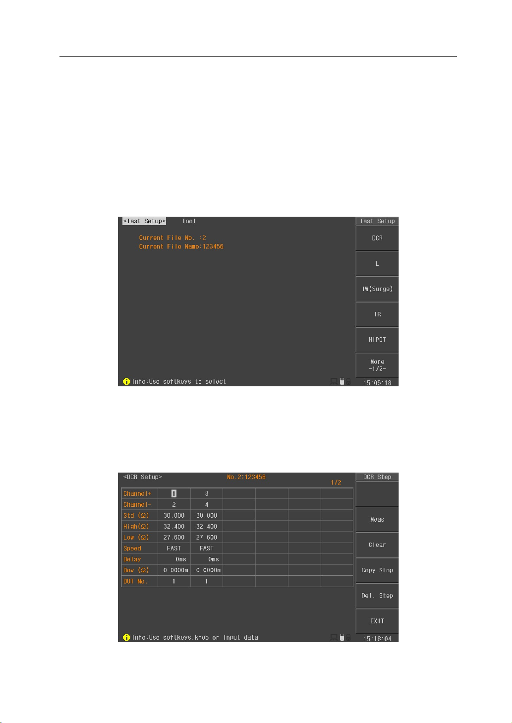
4.1 Test setup
Press SETUP menu key to enter into the test setup interface (as shown in figure 4-1-1).
Figure 4-1-1 Test setup page
4.1.1 DCR Setup
Press DCR key in Test Setup interface to enter into the DCR setup interface (as shown in figure
4-1-1-1).
Figure 4-1-1-1 DCR setup interface
U9036 Operation Manual Chapter 4 Instruction for Use
10
Channel+/channel-: Move the cursor to this zone and input the channel through the numeric key.
When inputting the channel+, the instrument will automatically set the next channel in channel-.
Channel+ means the high voltage positive terminal, while channel- means the high voltage
negative terminal. Channel+ and channel- can not be set at the same channel.
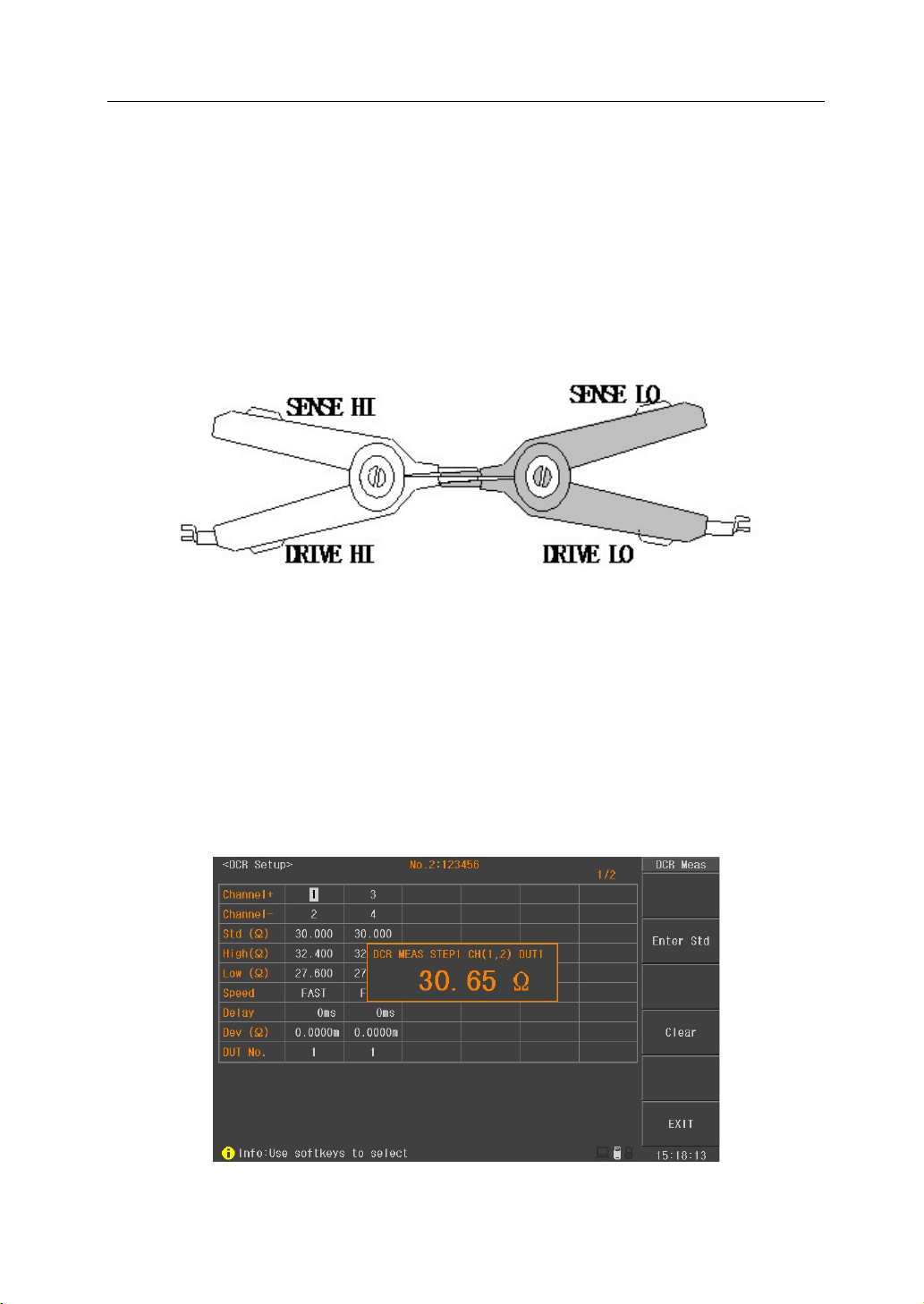
Clear: in order to acquire more accurate test results, clearing operation must be done after setting
the channel. Before clearing, please short the test clips of selected channel correctly according to
figure 4-1-1-2.
Figure 4-1-1-2 correct short the clips
Std(Ω): set the standard resistance of DUT. Move the cursor to this zone, use numeric key to input
the value or press “Meas” soft key to input it automatically. When using automatic input function,
please press “Meas” soft key after connecting the standard sample with the set channel. The
measured value will be displayed in the current page (figure 4-1-1-3). At this moment, press Enter
Std soft key to finish inputting the standard value. In measurement result display window,
correctly short the clips refer to figure 4-1-1-2 and then press Clear soft key to finish clearing
operation.
Figure 4-1-1-3 DCR test

U9036 Operation Manual Chapter 4 Instruction for Use
11
High/Low: set the high and low value. If the test result is out of the range, it will be judged as FAIL.
Move the cursor to this zone, use numeric key to input the value or press “% Calc” soft key to
input the percentage. When pressing “% Calc” soft key, calculation window will be displayed
(figure 4-1-1-4). Use numeric key to input the limit and press “OK” soft key, the instrument will
automatically calculated the high and low value.
Figure 4-1-1-4 % Calc of High/Low
Speed: set the test speed of DCR. When in SLOW, the test speed is the slowest but with the best
stability. When in FAST, the test speed is the fastest but with the bad stability. Move the cursor to
this zone, use soft key to select the test speed: FAST, MEDIUM, SLOW.
Delay: set the delay time before DCR test. When testing coils with large inductance, it is better to
set the delay time for stable measurement signal. Move the cursor to this zone, use numeric key
to input the delay time. The range of delay time is :0s~60.000s.
Dev: deviation is used for correcting the test results. Each test result will be added the deviation.
Move the cursor to this zone, use numeric key to input the deviation value. Also, the deviation
value can be set to 0 by using soft key “Set to 0”.
DUT No.: For ease of identification, the DUT No. is displayed in the front of the test item when in
comprehensive test. Move the cursor to this zone, use numeric key to input the number. It can be
set as 1~6.

U9036 Operation Manual Chapter 4 Instruction for Use
12
4.1.2 L(Inductance) Setup
Press L key in Test Setup interface to enter into the L(inductance) setup interface (as shown in
figure 4-1-2-1).
Figure 4-1-2-1 L(inductance) setup interface
Channel+/channel-: Move the cursor to this zone and input the channel through the numeric key.
When inputting the channel+, the instrument will automatically set the next channel in channel-.
Channel+ means the high voltage positive terminal, while channel- means the high voltage
negative terminal. Channel+ and channel- can not be set at the same channel.
Clear: in order to acquire more accurate test results, clearing operation must be done after setting
the channel. Before clearing, please short the test clips of selected channel correctly according to
figure 4-1-2-2.
Figure 4-1-2-2 correct short the clips
Para: set the test parameter of inductance. Move the cursor to this zone, use soft key to select the
test parameter: Ls-Q and Lp-Q.

U9036 Operation Manual Chapter 4 Instruction for Use
13
Frequency: set the test frequency of inductance. Move the cursor to this zone, use soft key to
select the test frequency: 50Hz,60Hz,100Hz,120Hz,1kHz,10kHz,20kHz,40kHz,50kHz and 100kHz.
Level: set the test level of inductance. Move the cursor to this zone, use soft key to select the test
level: 0.1V,0.3V and 1.0V.
Std(H): set the standard inductance of DUT. Move the cursor to this zone, use numeric key to input
the value or press “Meas” soft key to input it automatically. When using automatic input function,
please press “Meas” soft key after connecting the standard sample with the set channel. The
measured value will be displayed in the current page (figure 4-1-2-3). At this moment, press Enter
Std soft key to finish inputting the standard value. In measurement result display window,
correctly short the clips refer to figure 4-1-2-2 and then press Clear soft key to finish clearing
operation.
Figure 4-1-2-3 L(Inductance) test
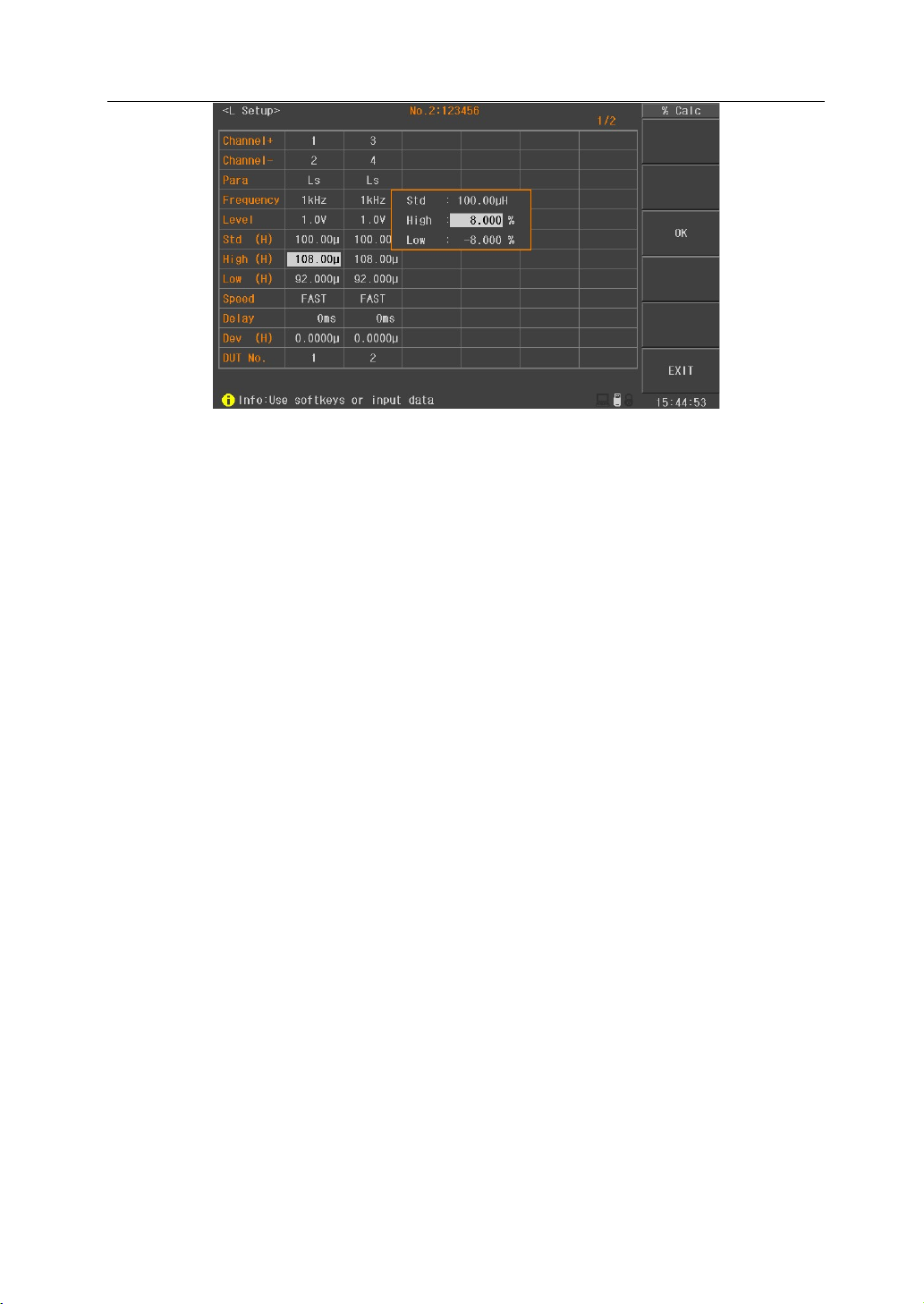
High/Low: set the high and low value. If the test result is out of the range, it will be judged as FAIL.
Move the cursor to this zone, use numeric key to input the value or press “% Calc” soft key to
input the percentage. When pressing “% Calc” soft key, calculation window will be displayed
(figure 4-1-2-4). Use numeric key to input the limit and press “OK” soft key, the instrument will
automatically calculated the high and low value.
U9036 Operation Manual Chapter 4 Instruction for Use
14
Figure 4-1-2-4 % Calc of High/Low
Speed: set the test speed of inductance. When in SLOW, the test speed is the slowest but with the
best stability. When in FAST, the test speed is the fastest but with the bad stability. Move the
cursor to this zone, use soft key to select the test speed: FAST, MEDIUM, SLOW.
Delay: set the delay time before inductance test. When testing coils with large inductance, it is
better to set the delay time for stable measurement signal. Move the cursor to this zone, use
numeric key to input the delay time. The range of delay time is :0s~60.000s.
Dev(H): deviation is used for correcting the test results. Each test result will be added the
deviation. Move the cursor to this zone, use numeric key to input the deviation value. Also, the
deviation value can be set to 0 by using soft key “Set to 0”.
DUT No.: For ease of identification, the DUT No. is displayed in the front of the test item when in
comprehensive test. Move the cursor to this zone, use numeric key to input the number. It can be
set as 1~6.
4.1.3 IW (Surge) setup
Press IW(Surge) in Test Setup interface to enter into the IW(Surge) setup interface (as shown in
figure 4-1-3-1).

U9036 Operation Manual Chapter 4 Instruction for Use
15
Figure 4-1-3-1 IW(Surge) setup page
Volt Adj: For a given impulse voltage, when the DUT is different, the actual voltage applied on
each DUT may also be different. Therefore, the voltage adjust function can automatically change
the output voltage and make all voltages applied across all DUT identical. Voltage adjustment is
particularly suitable for small inductance coil. Move the cursor to this zone, using soft keys to
turn ON/OFF the voltage adjust function.
Coro Mode: Move the cursor to this zone and use the soft key to select the corona mode. The
corona mode includes the following: peak, totals and jitter. Peak mode makes comparison by using
the calculated maximum corona results; sum mode makes comparison by using the calculated
accumulated corona results; jitter mode makes comparison by using the accumulated corona
results of some interval.
Std Comp: Move the cursor to this zone and turn ON/OFF the standard comparison function by
using the soft keys. When setting the comparison function as ON, comparison test of test
waveform and standard waveform will be made; When setting the comparison function as OFF,
comparison test of test waveform and standard waveform will not be made (there is no need to
make comparison between the corona and the standard waveform, so it is in normal test). In this
case, the inter layer balance function can be used to judge the consistency between the motor
winding. Please see details in section 4.1.2 IW BAL Setup.
Channel+/channel-: Set the channel through the numeric key. When inputting the channel+, the
instrument will automatically set the next channel in channel-. Channel+ means the high voltage
positive terminal, while channel- means the high voltage negative terminal. Channel+ and
channel- can not be set at the same channel.
Voltage: After setting the channel, move the cursor to test voltage and set the test voltage
U9036 Operation Manual Chapter 4 Instruction for Use
16
through the numeric key. The test voltage range is from 100V to 5000V.
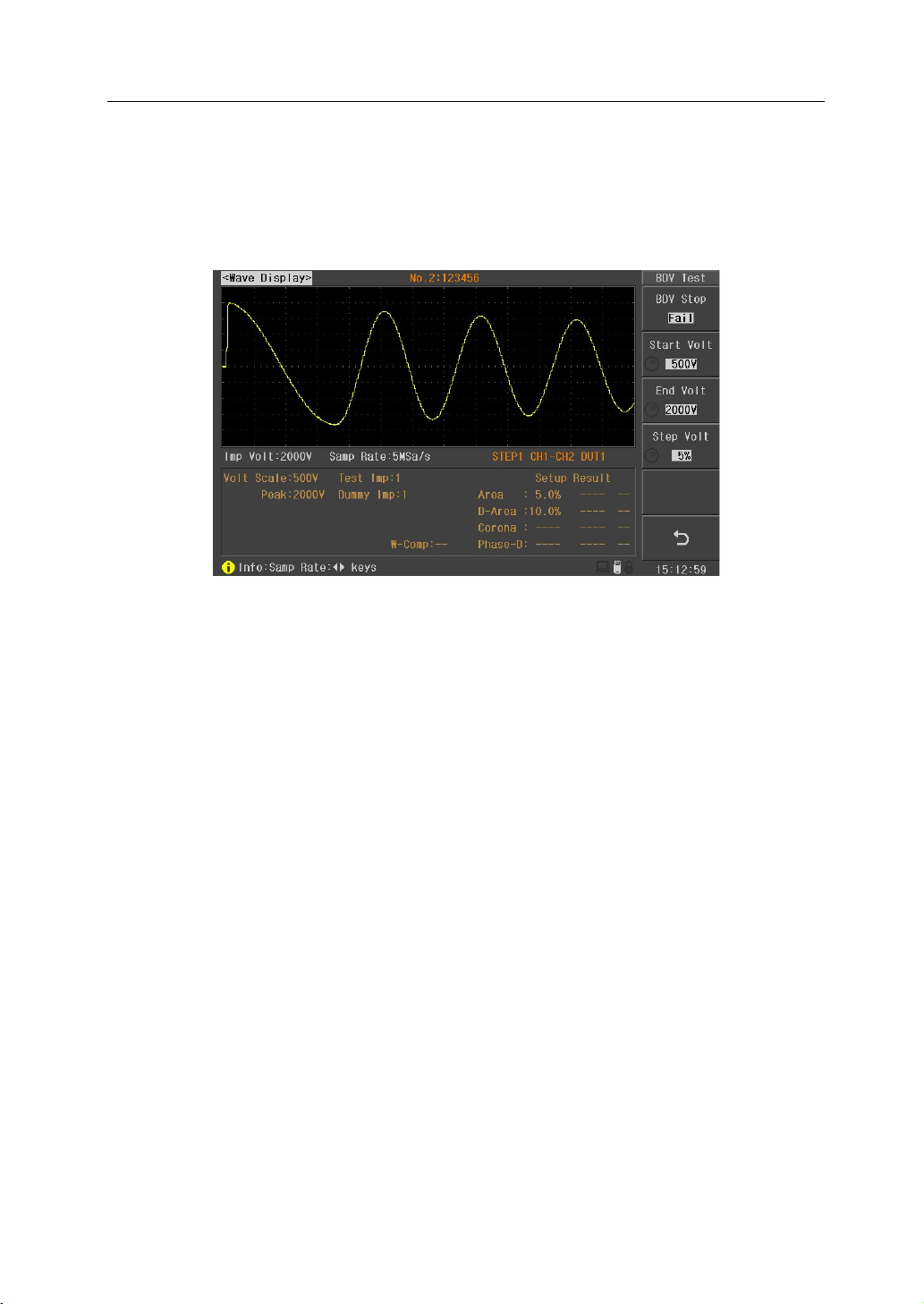
BDV test: BDV test is a test method used for judgment of limit withstand voltage of DUT. Starting
from Start Volt and ending at End Volt by a resolution of Step Volt, the test is finally done by
corona comparison. Move the cursor to Voltage zone and press BDV test soft key to enter into the
BDV test page (figure 4-1-3-2).
Figure 4-1-3-2 BDV test page
BDV Stop: set the BDV test to stop when the test fails or end when reaches the End Voltage.
Start Volt& End Volt: set the start voltage and end voltage of BDV test.
Step Volt: set the step of BDV test, ranging from 1%~50%.
NOTE: please set the Corona test function as ON before BDV test.
NOTE: the current voltage will be recorded when the BDV test encounter failure. The
recommended test voltage will be given after testing and it can be used as the test voltage by user.
Man Std: IW(Surge) test uses waveform compare to test, so to be compared with the test
waveform of DUT, standard waveform must be sampled before testing. After setting Channel+,
channel-, test voltage, test mode, dummy impulse and test impulse, press Man Std soft key to
enter into the Man Std interface (figure 4-1-3-3). After entering into the Man Std interface,
connecting the standard component with the high voltage output terminal and press START key to
sample. The waveform will be displayed in the screen after sampling. If the displayed waveform is
too wide or too narrow, use left and right key to adjust the sampling rate until the suitable
waveform is displayed. The test voltage (use rotary knob or numeric key or up and down key) and
test mode (use Mode key) can be modified in standard sampling page. Press return key to go back
to the IW(Surge) setup page after sampling. At this time, “S” symbol is displayed in the left side
of channel+ of the standard waveform, meaning the standard waveform of this channel has
been sampled.

U9036 Operation Manual Chapter 4 Instruction for Use
17
Figure 4-1-3-3 Man Std page
Mode: IW(Surge) uses waveform compare method to test. If the inductance value of the measured
object is too small, the oscillating waveform is not obvious. Making comparison test of this
waveform will result in great error with only a slight gap between the measured waveform and
standard waveform. Therefore, the instrument can be selected as the low inductance mode
(option) according to the characteristics of the DUT and then the oscillation waveform will be
enlarged and comparison test will be made. Move the cursor to the test mode, then use the
"Select" soft key to select Normal or low inductance test mode. Note that in low inductance mode,
you can set the maximum test voltage to 2000V.
Dummy Imp: Dummy impulse is number of times of high voltage applied to the DUT. The magnet
of motors and other coils still remain residual magnetic field after cutting the power. When pulse
testing is conducted in this case, there are significant differences in the first test waveform and the
second and subsequent test waveforms. Adding the dummy impulse can avoid this situation and
so as to determine the good product and bad product. The machine does not make judgment of
good product and bad product when in dummy impulse. The waveform compare test will only be
made by applying a pulse to the measured object and waiting for the actual test. Move the cursor
to the dummy impulse position and then input it using the numeric keys to change the times of
dummy impulse. The range can be set from 0 to 8.
Test Imp: Test impulse is the impulse times applied to the DUT when testing. The average
calculation of several test waveform can improve the stability and reliability of the measurement
results. Move the cursor to this zone and then input it using the numeric keys to change the times
of test impulse. The range can be set from 1 to 32.
Area Size: area size is the synthesis of all areas covered between the waveform and central line,
aiming at testing the energy loss in the winding. When a sample winding has a short circuit
Table of contents
Popular Test Equipment manuals by other brands

Lite-Check
Lite-Check CERTIFIER 1200 Operation manual

LION
LION alcolmeter 900 User handbook

Drummond
Drummond MTL20 instruction manual

Desco Europe
Desco Europe Charleswater 99037 Installation, operation and maintenance

PASCO
PASCO PS-2184 manual

pico Technology
pico Technology PicoDiagnostics PicoBNC+ quick start guide


Keysight
Keysight 1000B Series user guide

inTest
inTest THERMOSTREAM ATS-545 Interface & Applications manual

Walther
Walther E-boxx 780001502 Operating instruction and technical description

Blonder tongue
Blonder tongue BTPRO-7000 instruction manual

Martindale Electric
Martindale Electric EZ365 instruction manual

Apera Instruments
Apera Instruments ZenTest PC60-Z instruction manual