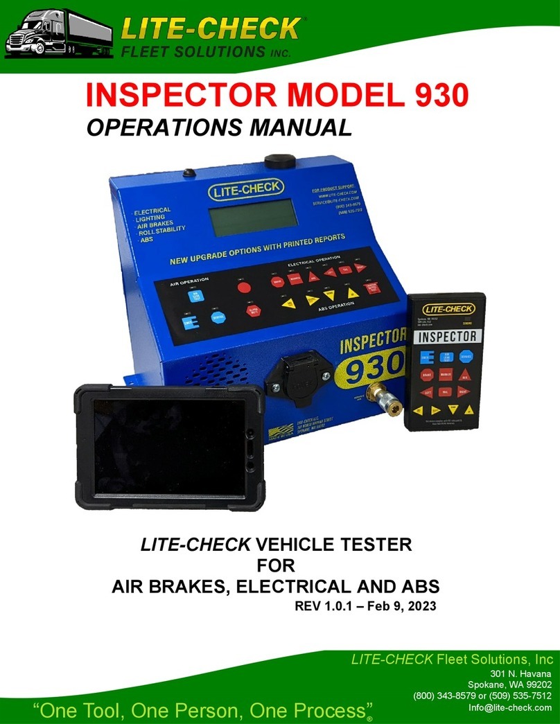
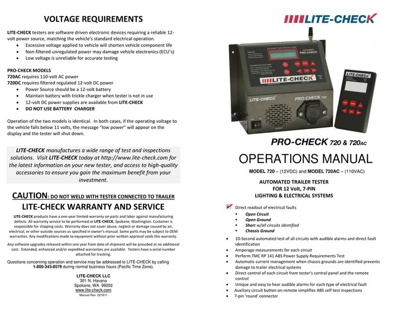
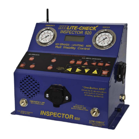
Lite-Check CERTIFIER 1200 User manual

LITE-CHECK CERTIFIER 1200
OPERATIONS MANUAL
LITE-CHECK CERTIFIER FOR
FMVSS/CMVSS 121-BRAKE TIMING TEST
WITH LIGHTS, AIR AND ABS
Version 1.0.0 Sept 25, 2019
301 N. HAVANA ST. lSPOKANE, WA 99202 l800-343-8579
WWW.LITE-CHECK.COM

CAUTIONS
USE ONLY CLEAN, DRY, OIL FREE, FILTERED AIR
►DO NOT connect the tester or release vehicle brakes without FIRST CHOCKING THE TIRES and
securely supporting the vehicle. The trailer can move(walk) during testing.
►DO NOT weld on the vehicle while the vehicle is connected to the tester. The tester is grounded
to the vehicle chassis and welding may damage the tester’s circuitry.
►DO NOT operate other systems or electrical devices on the vehicle during brake system testing.
Doing so may cause inaccurate results.
►Engines operating near the tester may interfere with remote control operation. If difficulty is
experienced, install electrical noise suppression on the offending engine.
►Each tester is matched to one remote control via Bluetooth. If you experience interaction of
remotes of multiple testers operated in close proximity, contact LITE-CHECK for assistance.
►For reliable remote control operation, the tester antenna must be fully exposed.
►EMERGENCY air must be supplied to the trailer’s brakes before the 1200’s SERVICE brake
function will operate. This prevents ‘Compounding’ and possible structural damage to brake
components.
►Use only air hoses and fittings as supplied by Lite-Check. Others may produce erroneous results
during brake timing tests.
►In order to safely perform consistent and accurate tests, operators of the LITE-CHECK 1200 must
first familiarize themselves with this manual, the tester, and the brake system being tested.
Should you have any questions, contact LITE-CHECK Technical Support at 800-343-8579, 7:00
am – 4:00 pm, Pacific Time, Monday through Friday.
Lite-Check CERTIFIER 1200 Operations Manual
2

Table of Contents
Lite-Check CERTIFIER 1200 Operations Manual
COVER………………………………………………………………………………………..……..
CAUTIONS……………………………………………………………………………………..……
TABLE OF CONTENTS……………………………………………………………………….…..
LITE-CHECK CERTIFIER 1200..……………………………………………………………..…..
Description…………………………………………………………………………………………………..….
Key Features of the Certifier 1200...…………..…..….…...…..……...…..…..…….………………...…….
Set-up Requirements…………………………………………………………………………………….…….
MODEL 400 HUB AND DOLLY………….……….………….………………….………………..
Description………………………………………………………………………………………………….…..
Hub Status LEDs…………………………………………………………………………………………..…..
LITE-CHECK TABLET and DESCRIPTION……………………..……………………………..
LITE-CHECK MODEL 363 DIFFERENTIAL KIT…………………………………………….…
Description………………………………………………………………………………………………….…..
Contains…………………………………………………………………………………………………….…..
LITE-CHECK AIR PRESSURE SENSOR/TRANSDUCER and DESCRIPTION…………...
INITIAL SET-UP PROCEDURES………….…………………………………………………..….
Shop Set-up………………………………………………………………………………………………..……
1200 CERTIFIER SELF-TEST PROCEDURES………....……………………………..….……
Test 1: Internal Self-Leak Test Without a Trailer or Dolly……………………………..……………….….
Test 2: 121 Timing Self-Test Without a Trailer or Dolly……………………………………………………
Test 3: Brake differential Self-Test Without a Trailer or Dolly…………………………….……………….
TESTER OPERATION, GENERAL………………………………………………………..……..
General……………………………………………………………………………………………….….…….
Functions of Keys, Panel and Tablet ..…...…….…..……..….……..…….….………………….…………
Notes..…..…..…..….…..……………………..……..…………………………………………………………
VERIFY THE TABLET IS CHARGED AND FUNCTIONAL……………………………………
INTERPRETING PANEL DISPLAYS, INDICATORS AND ALARMS…….…………………
General…………………………………………………………………………………………………………
Switch Indicators, LED………………………………………………………………………………………..
Audio Alarms…………………………………………………………………………………………………..
LITE-CHECK CERTIFIER SOFTWARE………………………………………………………..
General…………………………………………………………………………………………………………
Upgrading Your LITE-CHECK CERTIFIER Software……………………………………….………………
PERFORMING TESTS ON AN ACTUAL TRAILER OR DOLLY………………………..……
Performing the Air Leak Test when Attached to a Trailer or Dolly………………….…..…………………
Performing the 121 Timing Test when Attached to a Trailer or Dolly……………………………………..
Performing the Service Brake Differential Pressure Test on a Trailer or Dolly………………………..…
Performing ABS Tests.….….….….……….…..….……………………………………….…………………..
WHAT YOU WILL SEE ON THE 1200 CERTIFIER GUI SCREENS………………..………..
Main 1200 Startup Screen (General Overview)..….….….……….….….….….….…….…………………
SETUP Testing “Controller Dropdown”..……...…..….…...….….…..…..….…….…..…..….….…………
SETUP Testing “Hub Dropdown”……………………………………………………………………….…….
SETUP Testing “Help Dropdown”……….….…..….……………………………….…………………..……
SETUP Testing “Settings Dropdown (Page 1 of 2)”…………………………….…………………………..
SETUP Testing “Settings Dropdown (Page 2 of 2)”…………………………………………………………
Automatically Running Tests (Page 1 of 3) Enter Info, select tests, start tests…………..………..……
Automatically Running Tests (Page 2 of 3) Electrical tests in Progress…………..……………………..
Automatically Running Tests (Page 3 of 3) Electrical test done, Air Leak test started.………..……….
Sensor setup for 121 Timing test and Differential test…..……….….….….……..……………………..…
121 Timing test passed.…..…..……….…….….….…..…….…...…..….….…..….…...….….……….……
Differential test while running……..…………….....…….…....…...…..…………………..………………....
Passed Differential test...….…..…………....……..…..….….…..…..….….…..…………...…….……....…
Results of Failed Differential test ………………..…..……….…..…...…..…..………………………….…
Summary page which shows after tests are completed………….…..…..…..………………………….…
1
2
3
5
5
5
5
6
6
6
7
7
7
7
8
8
8
9
10
11
13
15
15
15
15
16
16
16
16
16
17
17
17
18
18
19
21
23
24
24
25
26
27
28
29
30
31
32
33
34
35
36
37
37
38
3

Lite-Check CERTIFIER 1200 Operations Manual
4
APPENDIX…………………………………………………….…….…………….….….….….…….
7-Way Wiring System, Pin Designations..…...…..…...…….……….…...…..…..………..…..….………….
Normal Power-Up Procedure..…...…..…...…….……...…..…...…...…..…..…..…..…...………………..….
39
39
40
Table of Contents (continued)

Description
►Electronic diagnostic tester for heavy-duty trailers and dollies.
► Tests12V7pinlightingsystemsforshorts,chassisshorts,opens,andopengrounds.
►Tests air brake systems for leaks, proper operation, and apply/release timing (FMVSS 121).
►Tests service/control line pressure differential for trailers/dollies equipped to tow other vehicles.
►Gathers and interprets 121 brake response data to tester via remote data acquisition hub.
►Operates via tablet for remote control operation, or personal computer Graphical Use Interface
(GUI).
►Remote tablet provides convenient service brake cycling for slack adjustment verification.
►Remote tablet allows for efficient verification of vehicle lamp operation.
►Allows test data, including brake timing, to be saved to the computer and/or to be printed.
►Performs all ABS tests and configuring following manufacturers procedures.
►Reads and writes the following ABS manufacturers; Bendix, Haldex and Meritor-Wabco.
Key Features of the Certifier 1200
►GUI display for test results.
►System voltage display.
►System amp-draw display.
►Automatic fault alarm.
►Tablet for remote control operation provides one-person operation and testing.
►Overload protection prevents vehicle-wiring damage resulting from shorts to ground.
►User friendly brake inspections, air-leak tests and 121 brake timing tests.
►“Differential Kit” (for timing-testing dollies and trailers equipped to tow other vehicles).
►For 121 Timing tests only, a minimum of 2 sensors are required per axle tested outside of the
US, and just one is required in the US.)
Set-up Requirements
Electrical power, 110 vac
Compressed air, filtered, dry, 110 psi @ 10 scfm
Computer printer included
3/8” air fittings for transducer connection into brake chambers
Lite-Check CERTIFIER 1200 Operations Manual
LITE-CHECK CERTIFIER 1200
5

2 hub
status
LEDs
Antenna
Sensor
Ports/Channels
(4 more on opposite side)
Power
switch.
(Hold
down to
power off.) PN 17200 Sensor with cable
Description:
The hub picture above has the hub cover open for a better picture. Users should operate the hub
with the cover closed. The dolly the hub rests on is not shown in the picture.
The hub gathers data from up to eight (8) sensors, interprets that data, and transmits the result to
the 1200 Certifier. The hub communicates with your 1200 Certifier via an antenna mounted
under the bottom tray of the 1200.
HUB Status LEDs
►Green LED lit: Indicates normal operation
►Red LED lit: Indicates error condition in the hub
MODEL 400 HUB AND DOLLY
PART # 17190
Lite-Check CERTIFIER 1200 Operations Manual
6
Backlight
switch.
(Illuminates
the LCD
display.)
LCD
display
LCD display
brightness
adjustment

Lite-Check CERTIFIER 1200 Operations Manual
LITE-CHECK TABLET PN 18092
Description:
The tablet PC supplied with your 1200 Certifier permits operation of 11 tester functions from
up to 100 feet distance from the tester. Its 11 shape-coded buttons match those on the tester GUI
and activate the same functions. The tablet communicates with the tester via Bluetooth, and is non-
directional. For best operation, assure the receiving antenna on the tester is fully exposed and
not shrouded by metal.
Description:
This kit provides additional equipment necessary to perform that portion of the 121 brake-timing
Tests (Differential) which applies only to converter dollies and trailers designed to tow other
vehicles.
This test compares the incoming service pressure against the outgoing pressure and evaluates
its difference to FMVSS 121 specifications.
Contains:
►Additional atmospheric pressure sensor/transducer
7
LITE-CHECK MODEL 363 DIFFERENTIAL KIT, PN 18115
Differential Manifold PN 18115 This 50 CI Canister Assembly will also be used.
NOTE: The 50 CI Canister Assembly will also be used during differential tests, but it is not actually
part of the Differential Kit (PN 18115).

LITE-CHECK AIR PRESSURE SENSOR/TRANSDUCER
(Lite-Check PN 17200)
Lite-Check CERTIFIER 1200 Operations Manual
8
INITIAL SET-UP PROCEDURES for when the unit first arrives
Shop Set-up
Remove test station from shipping container. Verify condition and check items against content list.
Notify carrier of any shipping damage or loss. Notify LITE-CHECK of any item shortages.
1. On the right side of the tester, connect blue coiled hose to the “Service Air - Blue” bulkhead,
connect red coiled hose to the “Emergency Air - Red” bulkhead, and attach the 7-way cable.
2 Connect at least two sensors to the hub.
3. Unpack the printer and connect the AC power cord from the printer into the power strip at the
center-back of the printer shelf. Slide the printer into the far right side of the middle shelf.
4. Insert the spare battery for the hub into the battery charger which sits on the bottom tray inside
the 1200. Be sure the battery charger is plugged into the power strip at the center-back of the
printer shelf.
5. Install your shop air connector to the air filter/regulator on the left side of the tester. Do not
supply air at this time, but only when instructed. Assure shop air supply is capable of supplying
and maintaining clean air at 110 psi to the tester throughout all tests.
6. Connect shop 110 Vac power to test station.
7. Connect the 4-port USB hub (PN 18135) to an open USB port on the PC.
8. Connect the Mouse and the Keyboard to the 4-port USB hub.
Follow the Certifier Self-Test Procedures listed in Pages 9 - 14.
Call Lite-Check Technical Support at 800-343-8579 for assistance if needed.
Description:
►The 1200 Certifier comes standard with 2 sensors. Additional sensors are recommended
for testing additional brake chambers and as back-ups.
►Air pressure sensor/transducer with 9’ cable -PN 17200.
►Generally one sensor/transducer is connected to a service-brake chamber and one is
connected to an emergency-brake chamber.
►One sensor/transducer is connected to the 50 CI differential chamber at the back of the
trailer during differential testing.
►Sensors are connected to the remote hub (17179) with a 9’ shielded cable.
►Do not extend or shorten without first contacting Lite-Check.

1200 CERTIFIER SELF-TEST PROCEDURES
Purpose: To check the ‘zero’ air calibration of sensors and to check the tester for internal air
leaks, and to resolve any issues in them, as needed.
NOTE: Do not connect Tester to vehicle during any of these self-tests.
Lite-Check CERTIFIER 1200 Operations Manual
9
You will perform 3 unique tests in sequence to be sure your 1200 Certifier is ready to be used for
testing. The 3rd test (Differential test) will only need to be done if you are testing a trailer or dolly
which is designed to tow another vehicle. All 3 tests are listed below.
1. Internal Air Leak Self-Test without a Trailer or Dolly
2. 121 Timing Self-Test without a Trailer or Dolly
3. Differential Self-Test*without a Trailer or Dolly
*The Differential Self-Test will only be done on vehicles designed to tow other vehicles.
All tests will be discussed in detail on the following pages.

2. Perform the “Normal Power-up Procedure” detailed in the Appendix, starting on page 39.
3. Enter “SELF CAL” in the VIN location in the Trailer Information Panel, which is the left side of
the display shown on the GUI, and pick “Self Calibration” in the Configuration box on the
Trailer Information Panel.
4. On the GUI, select “Air Leak”, “121 Timing” (and “Differential” if you will be testing a vehicle
that is designed to tow other vehicles). Then click ‘START’ on the GUI. The Internal Air Leak
test will start.
5. If the Internal Air Leak test FAILS: FAIL = >2 POUNDS SERVICE
FAIL = >3 POUNDS EMERGENCY
5a. Select “Retry” on bottom right corner of Air Leak test page in the GUI.
5b. If it fails a 2nd time, pick “Cancel All Tests” on the left edge of the GUI and continue.
5.c. Engage the EMERGENCY and SERVICE air lines to get air into the system. Soap-test
the blocked-off glad-hands, external fittings and internal fittings as needed to locate the source
of the leak(s) and continue.
5d. Tighten fittings and thread seal them as needed and continue.
5e. Select ”START” again (as in step 4). If this retry fails, call LITE-CHECK for assistance.
If the Internal Air Leak test passes, the Tester will advance to the 121 Timing Test.
Lite-Check CERTIFIER 1200 Operations Manual
1.
Connect a sensor to any
of the hub ports and the
quick-disconnect of the
50 CI Canister
Assembly.
2.
Connect the service glad
hand to the glad hand of
the 50 CI Canister
Assembly.
10
3.
Block off the emergency
air line from the tester
using the “Gladhand
Shutoff with Chain”,
PN 20053.
Performing the Internal Air Leak Self-test, without being attached to a trailer or dolly:
1. Check that Certifier glad-hands are secure and tightly blocked off. See the picture and
instructions below to accomplish this. Be sure that the Certifier and the hub are powered
off whenever a sensor is attached or removed from any test hardware or a trailer.
This is the end of Internal Air Leak Self-Test, without being attached to a trailer or dolly.

Purpose: This test verifies that the components of the test system (air supply, hoses, fittings, glad-
hands, etc.) combined with the tester's inherent set and release times complies with the maxi-
mum permissible times specified in Figure 2 of FMVSS-121, S6.1.13 as amended (Set > 0.350 sec.
(+ .005 seconds) and Release > 0.700 sec. (+ .005 seconds)). Do not attempt vehicle brake timing
or differential tests if either of the composite times for the test system do not pass. Otherwise
you run the risk of failing otherwise 'good' vehicles. If you are failing vehicles for apply and release
timing, re-run this test to verify the test system's performance.
1. The hardware setup needed for the 121 Timing Self–Test is the same as was just used for the
Internal Air Leak Test, which should have just completed.
2. Verify the following LED’s status on the hub:
►The green LED should be lit indicating a good state.
►The red LED will be lit if the hub encountered an error condition. (Likely the sensor attached
to the hub did not self-calibrate and may be defective. Or, there may be air pressure in the line,
or, there may be a low battery condition in the hub.)
►To adjust the brightness of the display on the hub, you can adjust the small screw near the
lower right corner of the hub display.
3. The “Setup HUB Sensors” dialog should be displayed. In this dialog, identify the appropriate hub
port which has the sensor cable (coming from the 50 CI reservoir) attached to it. On that sensor
in the GUI, change “Unused” to “Curbside” to select it for use.
4. Now select “Done” in the lower right hand corner of the “Setup HUB Sensors” dialog popup.
The 121 Timing test should immediately start as a result of this action.
5. If the test is successful, the 1200 Certifier GUI will either:
- Advance to the start of the next test, which is the Differential Test (if it was selected to run) and
a dialog popup should be displayed telling you to connect the Diff Kit.
- OR the GUI will indicate the test passes and if you hit ‘Continue’ a “Certifier Report” will
display.
Lite-Check CERTIFIER 1200 Operations Manual
11
121 Timing Self-Test, without a trailer or dolly:
6. But if the 121 Timing test fails, the error will be shown which will identify the failure. The
reason for the failure will be given, such as the speed at which portions of the test were
completed, or for not selecting a valid sensor, etc.
► If the failure is due to a sensor issue, fix the issue and then click on “Retry”.
► If the failure is due to timing, you may have to adjust one or both of the valves on the
Air Manifold, and then click “Retry”. See the next page for how to adjust the two valves.
Please see the picture on the next page to identify the locations of the two valves.

Lite-Check CERTIFIER 1200 Operations Manual
12
This is the end of the 121 Timing Self-Test, without using a trailer or dolly.
To adjust the
SET time. To adjust the
RELEASE time.
121 Timing Self-Test, without a trailer or dolly (continued):
The SET time should read 350 - 355 milliseconds and the RELEASE time should read
read 700 - 705 milliseconds.
·To increase the SET time, turn the valve on the FRONT of the Air Manifold
clockwise.
·To decrease the SET time, turn the valve on the FRONT of the Air Manifold
counter-clockwise.
·To increase the RELEASE time, turn the valve on the RIGHT SIDE of the Air
Manifold clockwise using a large screwdriver.
·To decrease the RELEASE time, turn the valve on the RIGHT SIDE of the Air
Manifold counter-clockwise using a large screwdriver.

Perform a Brake Air Differential Self-Test on the 1200 only, not using a Trailer or a Dolly:
Set-up and perform the Brake Differential Self-Test:
This Differential Self-Test is performed to verify your 1200 Certifier is functioning properly so that
when a Differential Test is performed on an actual trailer or dolly in the future, the user will know that
the results are accurate.
The Differential Test only applies to vehicles equipped to tow other air brake vehicles, such as
dollies, short semi-trailers (for doubles and triples) and B-train front semi-trailers. The test
requirements are specified in FMVSS-121, Paragraph S5.3.5.
The purpose of a Differential Test is to verify the control signal passed through the rear SERVICE
glad-hands of a trailer being tested, to another towed trailer or dolly, varies no more than the
permitted amount from the signal controlling the brakes on the vehicle being tested. This permitted
difference depends on the SERVICE/Control input pressure to the vehicle being tested.
5 psi to less than 20 psi 1 psi difference or less
20 psi to less than 40 psi 2 psi difference or less
40 psi or greater 5% of the input pressure or less
This test requires attachment of the double glad-hand fitting assembly, also known as the
“Differential Kit” or “Diff Kit” (PN 18115). The Diff Kit is an option which can be purchased
separately from the 1200 Certifier.
1. Now that the Air Leak and 121 Timing self-tests have passed, a popup should be displayed telling
you to connect the Diff Kit. Before that can be done, disconnect the 50 CI tank from the
SERVICE glad-hand. Leave all the other connections intact.
2. The Diff Kit now needs to be attached to the SERVICE glad-hand. To do this properly, notice
the “Air Flow” direction sticker on the Diff Kit. Connect the SERVICE glad-hand from the 1200
Certifier to the correct glad-hand on the Diff Kit, which is identified by being sure the Air Flow will be
flowing out of the SERVICE glad-hand and into the Diff Kit. Then click on “Continue” in the popup.
Nat’l Highway Traffic Safety Admin., DOT
Lite-Check CERTIFIER 1200 Operations Manual
13
This test continues on the next page.

Set-up and perform the Brake Air Differential Test, with no trailer or dolly (continued):
NOTE: Immediately after that glad-hand in the Diff Kit is a brass nipple which has an orifice inside to
allow air flow into the Diff Kit at a specific rate. The size of the FMVSS-121 specified orifice is
0.0180 inches diameter (about diameter of a pin). Air must flow through this orifice before getting to
any sensors being used for this test.
3. Verify that a cable (attached earlier) is still connected to the “Sensor Port” on the right side of the
Tester. This cable and sensor is part of the Diff Kit.
4. Attach the 50 CI reservoir to the open glad-hand on the Diff Kit.
5. A sensor and cable assembly (PN 17200) should still be connected to the quick disconnect on
the 50 CI canister assembly. The sensor should still be connected to a port on the hub.
6. The “Setup Hub Sensors” view will now be shown. The sensor attached to the hub was
selected to be “Curbside” for the Air Leak and 121 Timing Tests. This sensor needs to be changed
from “Curbside” to “Rear”. Then click on “Continue” in the box below the list of Sensors. The
Differential Test will now start and run.
7. If the Test Passes, another popup will be shown notifying you to “Disconnect the Differential Kit”.
But you don’t technically have to disconnect it at this time to successfully complete this test. This
popup just shows up at the end of a successful Differential Test.
8. Now click on “Continue” on the popup. You will be shown a “Certifier Report” with the results
of the tests that have been run: The Air Leak Test and 121 Timing Test results are in the “AIR
CONDITIONS” portion of the Report. The Differential Test results are shown in the “DIFFERENTIAL
TEST” portion.
9. If the Test Fails, hit “Retry” to run the Differential Test again. If it fails a 2nd time, call LITE-
CHECK for assistance.
10. If the Test Passes, remove the Diff Kit and save the data from the Certifier Report if desired.
Lite-Check CERTIFIER 1200 Operations Manual
14
This is the end of the SERVICE Brake Differential Test with no trailer or dolly.

Functions of Keys, Panel, and Tablet:
GUI button and Tablet button Action/function (In air system test mode)
EMER EMER Pressurizes trailer Emergency/Supply system
(Trailer air supply).
SERVICE SERVICE Activates trailer Service/Control system
AIR LEAK- AIR LEAK- Blocks air supply to trailer and reads air loss in
TEST TEST system.
GUI button and Tablet button Action/function (In electrical system test mode)
BRAKE BRAKE Tests brake light circuit
MARKER MARKER Tests marker light circuit
AUX AUX Tests auxiliary power circuit & power to ABS
LEFT LEFT Tests left turn circuit
TAIL TAIL Tests tail light circuit
RIGHT RIGHT Tests right turn circuit
GUI button and Tablet button Action/function (Special function keys)
SELECT SELECT Selects test mode
NOTES
►Only one electrical circuit operates at one time.
Lite-Check CERTIFIER 1200 Operations Manual
15
General:
The system provides two means of tester operation: The tester’s tablet PC and the computer’s
Graphical User Interface (GUI). The key names and functions are listed below:
TESTER OPERATION, GENERAL
SELECT

Verify the Tablet is charged and functional:
►Start the “Certifier” app on the tablet by clicking on the proper icon.
►Only one electrical circuit operates at one time. Pressing a different 2nd key cancels the
previous. Pressing the same key 2 times without hitting any other key cancels that function.
►The actions of the tablet parallel that of the tester’s GUI.
►Activating a function via the tablet will illuminate the respective LED on the 1200 GUI display.
►The tablet can be programmed to operate with only one tester.
If you experience interference between tester systems and the tablet, contact LITE-CHECK
Technical Support for assistance at 1-800-343-8579.
INTERPRETING PANEL DISPLAYS, INDICATORS AND ALARMS
General:
The 1200 Certifier utilizes two on-board means of communicating with its operator:
1. Graphical User Interface (GUI) of the Certifier 1200 application loaded onto the PC
2. Audio Alarm with pitch-coded sound for faults
Lite-Check CERTIFIER 1200 Operations Manual
16
Switch Indicators, LED:
Indicators on the GUI will be activated whether circuit is activated by the Tablet or from the GUI.
►Steady indicator: Switch and circuit activated.
►Flashing indicator: Fault condition found in circuit being tested.
Audio Alarms:
►Fault alarm (Unique pitch assigned to each specific fault type)

LITE-CHECK CERTIFIER SOFTWARE
(PC Graphical User Interface or “GUI”)
General:
Your LITE-CHECK 1200 System includes the capability to operate the tester from the PC via the
CERTIFIER software GUI which is loaded onto a Windows PC. This software allows convenient
insertion of vehicle and work data such as VIN, Customer Name and Order Number into the test
record so this information becomes a permanent part of the record.
Once a test has been run (or a set of tests if more than one test was requested to run) the test results
are saved automatically in a report.
Saved data files (Reports) are stored on the PC’s hard drive and can be viewed and printed via
ADOBE or other PDF viewers. The user will specify a VIN Number into the Trailer Information Panel
just before the start of a test. (See page 24 for a sample of this Panel.) This VIN number will be
incorporated into part of the PDF file name of the Report. For example, if a user entered
“1234ABC” for the VIN number of a vehicle under test, the PDF file which will be generated when the
user saves the “Certifier Results” will be named “Report 1234ABC-[Date].PDF”.
Upgading your LITE-CHECK CERTIFIER Software:
The LITE-CHECK 1200 Certifier has the software already installed on the provided PC. Updates to
any of the software/firmware for the 1200 Certifier (GUI app, Tablet app or Hub firmware) should
ONLY be done if instructed to by LITE-CHECK Technical Support. Any needed files will be
provided by LITE-CHECK, and the process to install any updates will be provided to each customer
on an individual basis.
To start any update process, You must contact LITE-CHECK Technical Support at 800-343-8579,
7:00 am – 4:00 pm, Pacific Time, Monday through Friday.
Lite-Check CERTIFIER 1200 Operations Manual
17

Lite-Check CERTIFIER 1200 Operations Manual
Performing the Air Leak Test, when attached to a trailer or dolly:
1. Attach the EMERGENCY Air output glad-hand from the tester to the EMERGENCY glad-hand
port on the front of the vehicle under test (i.e. trailer or dolly). WARNING: Failure to connect
the Emergency air can cause brake “compounding” and damage the brake chamber!
2. Attach the SERVICE Air output glad-hand from the tester to the SERVICE glad-hand port on the
front of the vehicle under test.
3. Perform the “Normal Power-up Procedure” detailed in the Appendix which starts on page 39.
4. NOTE: The default length of time this test will take (set by Lite-Check) is 60 seconds. We
generally recommend this setting not be changed. But, you may adjust it if needed by selecting
the “Settings” tab at the top of the Main 1200 Startup Screen which should be displayed on the
GUI right now. Then see page 28 & 29 for how to navigate the Settings screen. If you do
modify the settings, be sure to click on ‘Done’ on the Settings page to return the GUI to the
Main 1200 Startup Screen.
5. Fill in the “Trailer Information Panel” with the appropriate data. (This panel is the left side of the
Main 1200 Startup Screen. The VIN number is required, so enter the VIN number for this
vehicle. Enter the Customer and Order Number as desired. Click the drop-down menu inside
the “Calibration” selection box to select the correct “Configuration” of the vehicle under test. Do
not choose “Self Calibration”. See page 24 for the “Configuration” choices available.
6. Click on “Start” in the Trailer Information Panel. The Air Leak test will start.
7. If the Internal Air Leak test FAILS:
FAIL = >2 POUNDS SERVICE
FAIL = >3 POUNDS EMERGENCY
7a. Select “Retry” on bottom right corner of Air Leak test page in the GUI.
7b. If it fails a 2nd time, pick “Cancel All Tests” on the left edge of the GUI.
7c. Engage the EMERGENCY and SERVICE air lines to get air into the system. Soap-test
the blocked-off glad-hands, external fittings, and internal fittings as needed to locate the source
of the leak(s).
7d. Tighten fittings and thread seal them as needed.
7e. Select ”START” again (as in step 6). If this retry fails, call LITE-CHECK for assistance.
This is the end of the Air Leak Test when the tester is attached to a trailer or dolly.
.
PERFORMING TESTS ON AN ACTUAL TRAILER OR DOLLY
18

Lite-Check CERTIFIER 1200 Operations Manual
19
PURPOSE:
This test is used to verify that components of the trailer or dolly under test (air supply, hoses, fittings,
glad-hands, brake cans, etc.) are in satisfactory condition to insure the tester's inherent set and
release times complies with the maximum permissible times specified in FMVSS-121 for the specific
type of vehicle being tested. Various types of vehicles are selectable on the “Main 1200 Startup
Screen” under the “Configuration” dropdown. (See page 24 for the vehicle choices.) If you are failing
vehicles for apply and release timing, re-run the “121 Timing Self-Test Without a Trailer or Dolly”
(on page 11) to verify the test system's performance, before testing actual vehicles again.
1. Perform the “Normal Power-up Procedure” detailed in the Appendix starting on page 39.
2. Connect a sensor to any port on the Hub, if there isn’t one already attached and ready for use.
3. Attach the EMERGENCY Air output glad-hand from the tester to the EMERGENCY glad-hand
port on the front of the vehicle under test (i.e. trailer or dolly). WARNING: Failure to connect
the Emergency air can cause brake “compounding” and damage the brake chamber!
4. Attach the SERVICE Air output glad-hand from the tester to the SERVICE glad-hand port on the
front of the vehicle under test.
5. Verify the following LED’s status on the Hub:
►The Green LED should be lit indication a good state.
►The the Red LED will be lit if the Hub encountered an error condition. (Likely the sensor
attached to the Hub did not self-calibrate and may be defective. Or, there may be air pressure in
the line. Or, there may be a low battery condition in the Hub.)
►To change the brightness of the display on the Hub, you can adjust the small screw near the
lower right corner of the Hub display.
6. The “Setup Hub Sensors” dialog will popup. Select the appropriate Hub port that matches where
you connected your sensor in Step 2, above. On that sensor selection in the GUI, change
“Unused” to “Curbside” to select it for use.
7. Now select “Done” in the lower right hand corner of the “Setup Hub Sensors” dialog popup. The
test will immediately start as a result of this action.
8. At test completion, the SUMMARY page will appear and display the results.
This test continues on the next page.
Performing the 121 Timing Test, when attached to a trailer or dolly:

Lite-Check CERTIFIER 1200 Operations Manual
20
10. The Test Report may be saved as a confirmation of the tester performance. To save, click on
“Save “ or “Save and Print”.
9. But if the 121 Timing test fails, the error will be shown which will identify the failure. The
reason for the failure will be given, such as the speed at which portions of the test were
completed, or for not selecting a valid sensor, etc.
► If the failure is due to a sensor issue, fix the issue and then click on “Retry”.
► If the failure is due to timing, you may have to adjust one or both of the valves on the
Air Manifold, and then click “Retry”. See below for how to adjust the two valves.
The SET time should read 350 - 355 milliseconds and the RELEASE time should read
read 700 - 705 milliseconds.
·To increase the SET time, turn the valve on the FRONT of the Air Manifold clockwise.
·To decrease the SET time, turn the valve on the FRONT of the Air Manifold counter-
clockwise.
·To increase the RELEASE time, turn the valve on the RIGHT SIDE of the Air Manifold
clockwise using a large screwdriver.
·To decrease the RELEASE time, turn the valve on the RIGHT SIDE of the Air Manifold
counter-clockwise using a large screwdriver.
This is the end of 121 Timing Test, using a trailer or dolly.
To adjust
the SET
time.
To adjust the
RELEASE
time.
Performing the 121 Timing Test, when attached to a trailer or dolly (continued):
Table of contents
Other Lite-Check Test Equipment manuals