Desco Europe Charleswater 99037 Installation and operating instructions
PPE-5111.E Page 1 of 6 © 2018 DESCO INDUSTRIES INC
Employee Owned
DESCO EUROPE - 2A DUNHAMS LANE, LETCHWORTH, HERTFORDSHIRE, SG6 1BE, UK
Combo Tester
Installation, Operation and Maintenance
Description
The Charleswater Combo Tester verifies the functionality
of an operator’s wrist strap and footwear (footwear
test requires foot plate). It determines if an operator’s
wrist strap and footwear will function correctly. A rocker
switch allows the operator to select a wrist strap or
footwear test. A green light indicates that the wrist strap
or footwear is passing. Red and yellow lights plus an
audible alarm indicate when the wrist strap or footwear is
failing. If failure occurs, the tester will also display if the
grounding device’s resistance is too low or too high.
The factory test limits are set to:
Wrist Straps: 750 Kilohms and 35 Megohms
Footwear: 750 Kilohms and 35 Megohms
Contact Desco Europe Customer Service if custom test
limits are required.
The Combo Tester is powered by a 9 volt battery. A
warning light on the tester indicates when the battery
power is too low and affecting the test results.
Each Combo Tester is calibrated with accepted
procedures and standards traceable to the National
Institute of Standards and Technology (NIST) and
includes a NIST certificate.
May 2018
This product can be used as one of the tools to fulfil
EN 61340-5-1 Compliance verification requirements.
“Process monitoring (measurements) shall be conducted
in accordance with a compliance verification plan that
identifies the technical requirements to be verified, the
measurement limits and the frequency at which those
verifications must occur. … Compliance verification
records shall be established and maintained to provide
evidence of conformity to the technical requirements.
The test equipment selected shall be capable of making
the measurements defined in the compliance verification
plan.”
“Wrist straps should be tested periodically. The
frequency of testing, however, is driven by the amount
of usage, wear and ESD risk exposure that can occur
between tests. For example, what is the quantity of
product handled between test periods? Typical test
programs recommend that wrist straps that are used
daily should be tested daily. However, if the products
that are being produced are of such value that a
guarantee of a continuous, reliable ground is needed
then continuous monitoring should be considered or
even required.” (CLC TR 61340-5-2 User guide Wrist
Strap clause 4.7.2.4.4 Test frequency)
“While wearing the wrist strap, connect the loose end
of the cord to the tester terminal and depress the test
button or touch the metal test surface with a finger or
hand. If the resistance is over 3,5 x 10⁷ Ω, test the cord
alone for continuity. If the resistance of the cord alone
is approximately 1,0 x 10⁶ Ω, check the fit of the band
around the wrist and adjust it for a snug fit. Snap the
cord back on the cuff and retest. If the resistance is
still over 3,5 x 10⁷ Ω, substitute a new band.” (CLC TR
61340-5-2 User guide Wrist Strap clause 4.7.2.4.3 Test
procedure)
“The operator shall stand with one foot on the
conductive footwear electrode. The hand contact plate
shall be pressed to verify that the person footwear
system resistance is within acceptable parameters.
The test shall be repeated for the other foot. The test
apparatus can be an integrated, commercially available
tester.” (EN 61340-5-1 Annex A Test method A.2
Measurement procedure for footwear testing)
Item Description
99037 Combo Tester
99038 Combo Tester with Stand and Foot Plate
99013 Stainless Steel Foot Plate
Made in the
United States of America
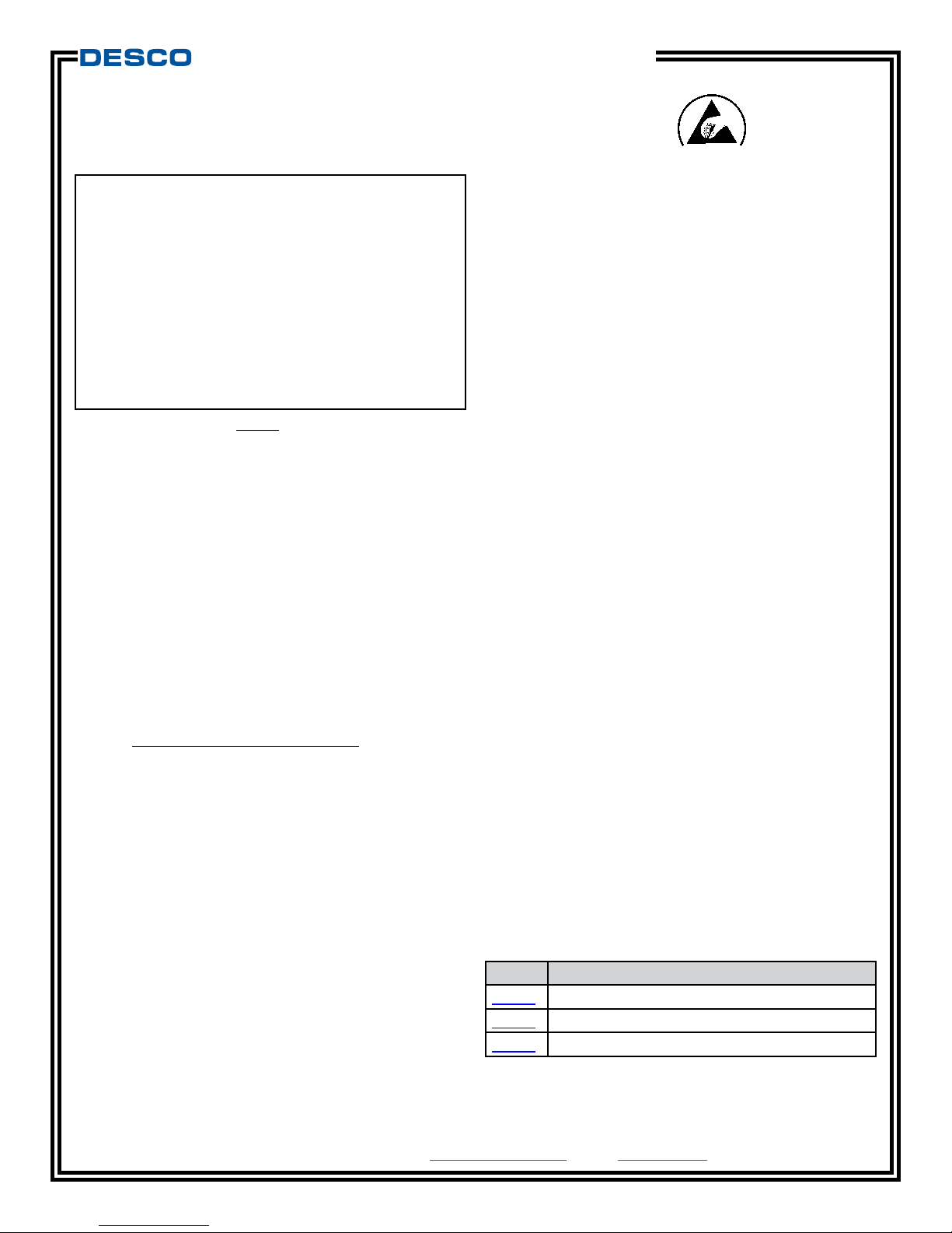
Figure 1. Charleswater 99037 Combo Tester
TECHNICAL BULLETIN PPE-5111.E
EUROPE

PPE-5111.E Page 2 of 6 © 2018 DESCO INDUSTRIES INC
Employee Owned
DESCO EUROPE - 2A DUNHAMS LANE, LETCHWORTH, HERTFORDSHIRE, SG6 1BE, UK
Packaging
99037 COMBO TESTER
1 Combo Tester
1 Foot Plate Cord, 12.7 cm
1 80020 Banana Plug / 10 mm Adapter
1 9 V Battery
1 Certificate of Calibration
99038 COMBO TESTER WITH STAND AND FOOT
PLATE
1 Combo Tester
1 Foot Plate Ground Wire, 12.7 cm
1 80020 Banana Plug / 10 mm Adapter
1 9 V Battery
1 Foot Plate
1 Pedestal
3 Button Head Screws, 1/4-20 x 3/4”
1 Allen Wrench, 5/32”
1 Flat Head Screw, 8-32 x 5/8”
1 Knurled Nut, 8-32
1 Black Cap
1 Poster
1 Certificate of Calibration
Both the 99037 and 99038 Combo
Testers include a Desco Europe
80020 10 mm Adapter. This is used
to convert the banana jack on the
face of the tester to a 10 mm snap.
Note that this adapter is permanent
and cannot be removed once it is
installed.
99013 STAINLESS STEEL FOOT PLATE
1 Stainless Steel Foot Plate
1 Foot Plate Cord, 183 cm
Figure 2. Charleswater 99038 Combo Tester with Stand
and Foot Plate
Figure 3. Charleswater 99013 Stainless Steel Foot Plate
PPE-5111.E Page 3 of 6 © 2018 DESCO INDUSTRIES INC
Employee Owned
DESCO EUROPE - 2A DUNHAMS LANE, LETCHWORTH, HERTFORDSHIRE, SG6 1BE, UK
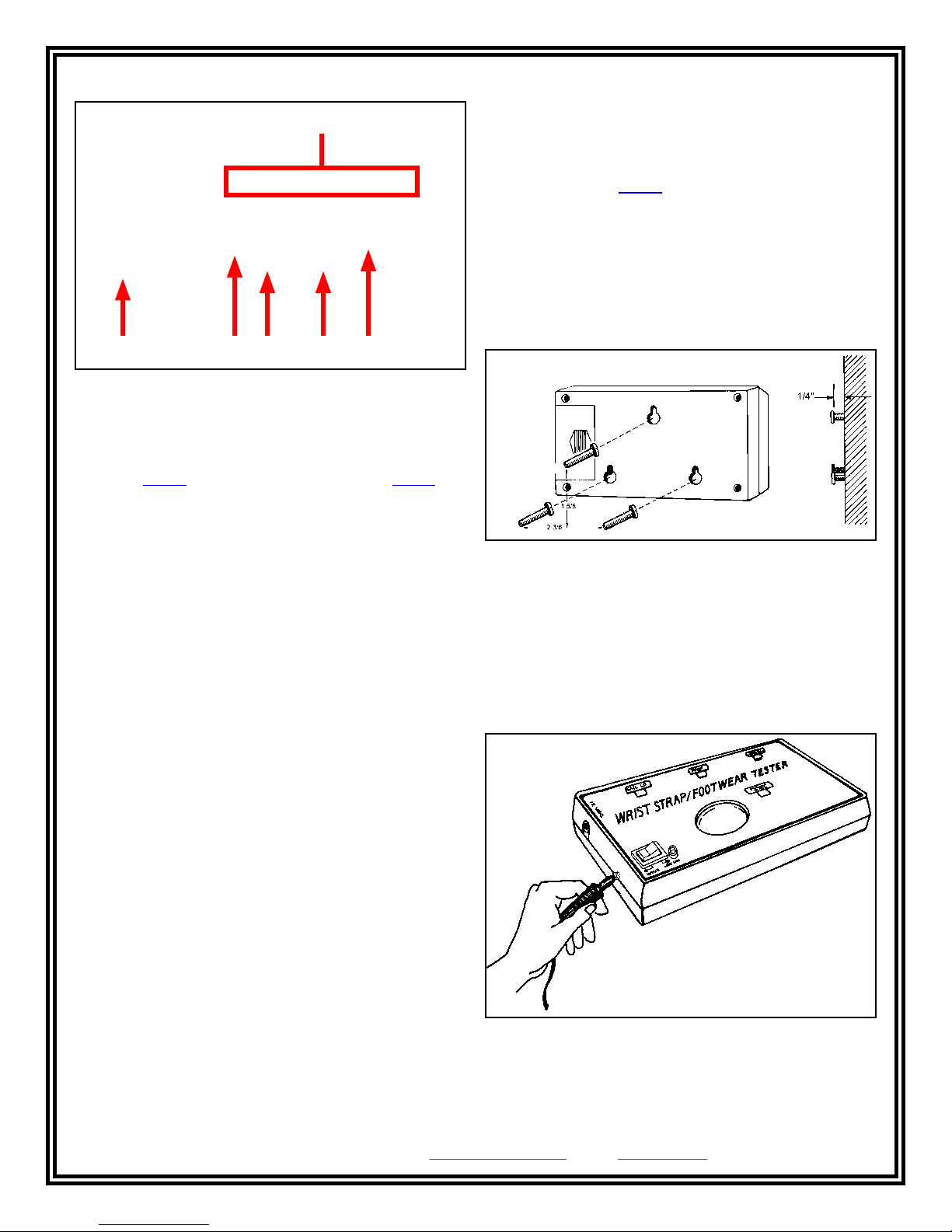
Features and Components
A. Test Result LEDs: Displays the test results.
B. Foot Plate Jack: Connect the banana plug terminal
of the foot plate cord here and the other end to the
pedestal (99038) or stainless steel foot plate (99013).
C. Rocker Switch: Toggle to the left when performing
a footwear test. Toggle to the right when performing a
wrist strap test.
D. Single-Wire Wrist Strap Jack: Insert your
single-wire wrist cord here to test your wrist strap.
E. Test Switch: Push down and hold your finger here
to perform a test.
F. Low Battery LED: Illuminates when the battery
power is low and needs to be replaced.
Figure 4. Combo Tester features and components
A
B C D E F
Installation
The Combo Tester is portable, but it also has the
flexibility of being permanently installed at a location.
Use the three keyhole slots located on the back of the
Combo Tester to mount it to a wall or stand.
INSTALLING THE 99037 COMBO TESTER
1. Install the 9 V alkaline battery into the Combo
Tester.
2. Select a location to mount the Combo Tester.
3. Install three #6 or #8 screws into a wall or other
vertical surface as shown in the figure below. Make
sure that the screw heads do not project out more
than 6.35 mm from mounting surface.
Figure 5. Combo Tester keyhole slots
4. Mount the Combo Tester onto the screws, and pull
it down to secure it into place.
5. Set the Stainless Steel Foot Plate below the tester
(if applicable).
6. Insert the 183 cm long foot plate cord’s banana plug
into the Combo Tester’s foot plate jack.
Figure 6. Inserting the foot plate cord’s banana jack into
the Combo Tester
7. Snap the opposite end of the foot plate cord onto
the Stainless Steel Foot Plate.
PPE-5111.E Page 4 of 6 © 2018 DESCO INDUSTRIES INC
Employee Owned
DESCO EUROPE - 2A DUNHAMS LANE, LETCHWORTH, HERTFORDSHIRE, SG6 1BE, UK
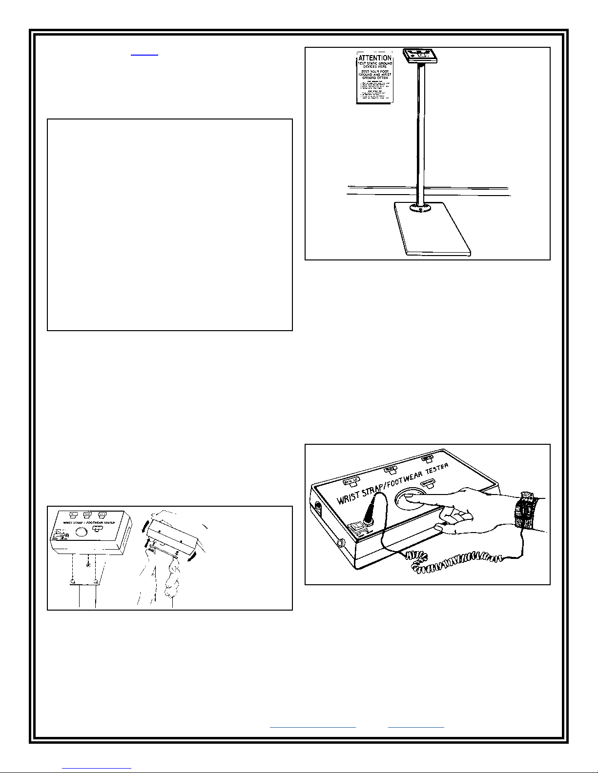
INSTALLING THE 99038 COMBO TESTER WITH
STAND AND FOOT PLATE
1. Position the pedestal on top of the foot plate with
the mounting bracket sloping toward the operator.
Secure the pedestal to the foot plate using the 3
included button head screws and allen wrench.
Figure 7. Securing the pedestal to the foot plate
2. Install the 9 V alkaline battery into the Combo
Tester.
3. Mount the Combo Tester onto the pedestal’s
mounting bracket and flat head screw, and screw
down to secure it into place.
4. Insert the 12.7 cm long foot plate cord’s banana
plug into the Combo Tester’s foot plate jack.
5. Attach the foot plate cord’s ring terminal to the flat
head screw located at the back of the pedestal’s
mounting bracket, and tighten the knurled nut to
secure.
Figure 8. Installing the Combo Tester to the pedestal
6. Cover the knurled nut and flat head screw with
included insulative vinyl cap.
7. Install the included poster at eye level nearby the
test station.
Operation
WRIST STRAP TEST
1. While wearing a wrist strap, plug the wrist cord
into the wrist strap jack located on the face of the
Combo Tester.
2. Toggle the rocker switch to the right toward WRIST
STRAP.
3. Push down and hold the test switch until the test
results are displayed. DO NOT touch any other
metal while performing your test as this will affect
your results.
Figure 9. Completed Combo Tester with Stand and Foot
Plate assembly
Figure 10. Performing a wrist strap test
PPE-5111.E Page 5 of 6 © 2018 DESCO INDUSTRIES INC
Employee Owned
DESCO EUROPE - 2A DUNHAMS LANE, LETCHWORTH, HERTFORDSHIRE, SG6 1BE, UK
4. A “PASS” test result is indicated by illumination of
the green LED. A “FAIL LOW” test result is indicated
by illumination of the red LED. A “FAIL HIGH” test
result is indicated by illumination of the yellow LED.
If your ESD test fails, check your wrist strap and
ensure that it is being worn correctly and/or needs
to be replaced.
NOTE 1: The Combo Tester may briefly display “FAIL
HIGH” once the test button is released at the conclusion
of a test. Residual voltage in the circuit’s capacitors
causes the test to continue for a split second after the
button is released.
NOTE 2: Failures may be caused by dry skin or minimal
sweat layer. For wrist straps, try using an approved
dissipative hand lotion such as Reztore™ ESD Hand
Lotion to your wrist prior to use.
The Combo Tester may also be used to test smocks
or garments that feature a grounding mechanism for
operators using a coiled cord connection.
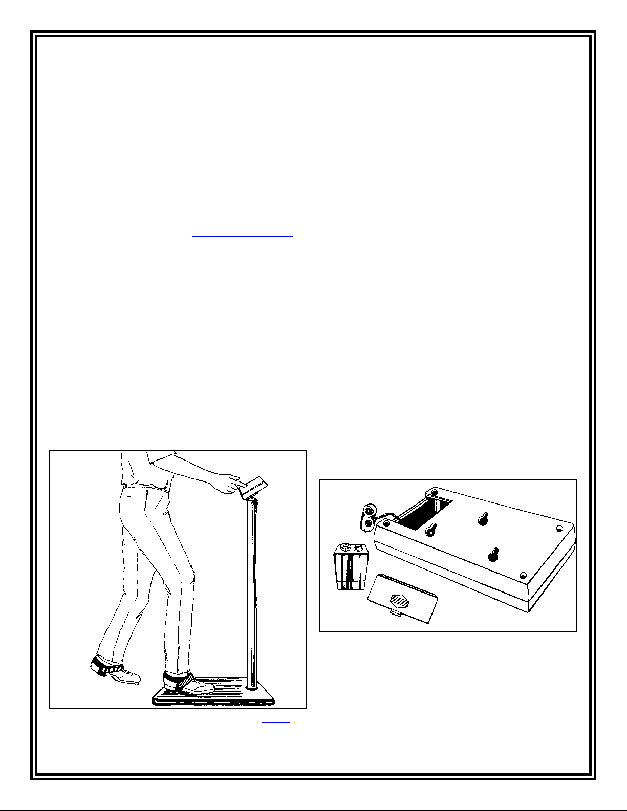
FOOTWEAR TEST
1. Toggle the rocker switch to the left toward FOOT
PLATE.
2. While wearing ESD footwear, place one foot on the
foot plate, and lift the second foot off the floor. Make
sure there is no wrist cord plugged into the WRIST
STRAP jack.
3. Push down and hold the test switch until the test
results are displayed. DO NOT touch any other
metal while performing your test as this will affect
your results.
Figure 11. Performing a footwear test with the 99038
Combo Tester with Stand and Foot Plate
4. A “PASS” test result is indicated by illumination of
the green LED. A “FAIL LOW” test result is indicated
by illumination of the red LED. A “FAIL HIGH” test
result is indicated by illumination of the yellow LED.
If your ESD test fails, check your footwear and
ensure that it is being worn correctly and/or needs
to be replaced.
NOTE 1: The Combo Tester may briefly display “FAIL
HIGH” once the test button is released at the conclusion
of a test. Residual voltage in the circuit’s capacitors
causes the test to continue for a split second after the
button is released.
NOTE 2: Failures may be caused by dry skin or minimal
sweat layer. Footwear test results can be improved
by taking a short walk to build a sweat layer for better
conductivity.
5. Repeat steps 2-4 for the second foot.
Maintenance
The Combo Tester requires little maintenance. There
are no user serviceable parts. If your meter requires
service beyond cleaning the test switch or foot plate,
please contact the factory.
Use a minimum of 80% isopropyl alcohol to clean the
test switch. Other cleaners are susceptible to leaving
residue.
BATTERY REPLACMENT
The low battery indicator flashes briefly every time
the unit is used. Replace the battery once the
indicator becomes constant during testing. Open the
compartment located on the back of the tester to
replace the battery. The tester uses one 9 V alkaline
battery.
Figure 12. Replacing the battery

PPE-5111.E Page 6 of 6 © 2018 DESCO INDUSTRIES INC
Employee Owned
DESCO EUROPE - 2A DUNHAMS LANE, LETCHWORTH, HERTFORDSHIRE, SG6 1BE, UK
Calibration
The Charleswater Combo Tester is calibrated to NIST
traceable standards. There are no user adjustments
necessary. We recommend that calibration be
performed annually using the Charleswater 99090
Calibration Unit. It is a convenient product which allows
the customer to perform NIST traceable calibration on
single-wire personnel testers. The 99090 is designed to
be used on the shop floor at the workstation, virtually
eliminating downtime, verifying that the tester is
operating within tolerances.
View technical bulletin PPE-5034.E for more information
on the 99090 Calibration Unit and instructions to
calibrate the Combo Tester.
Figure 13. Charleswater 99090 Calibration Unit
Specifications
COMBO TESTER
Power Supply 9 V Alkaline Battery
Operating Temperature 32 °F to 104 °F
(0 °C to 40 °C)
Wrist Strap Test Limit 750 Kilohms to 35 Megohms
Footwear Test Limit 750 Kilohms to 35 Megohms
Test Accuracy ±20%
Test Voltage 4 VDC
Dimensions 3.3" x 5.6" x 1.5"
(8.4 cm x 14.2 cm x 3.8 cm)
Weight: 0.5 lbs (0.2 kg)
STAND AND FOOT PLATE
Stand Height 36" (91 cm)
Foot Plate Dimensions 18" x 12" x 1"
(46 cm x 30 cm x 3 cm)
Weight 8.0 lbs (3.6 kg)
STAINLESS STEEL FOOT PLATE
Dimensions 20" x 20" x 0.5"
(51 cm x 51 cm x 1 cm)
Weight 5.5 lbs (2.5 kg)
Limited Warranty, Warranty Exclusions, Limit
of Liability and RMA Request Instructions
See the Desco Europe Warranty -
DescoEurope.com/Limited-Warranty.aspx
Table of contents
Other Desco Europe Test Equipment manuals


