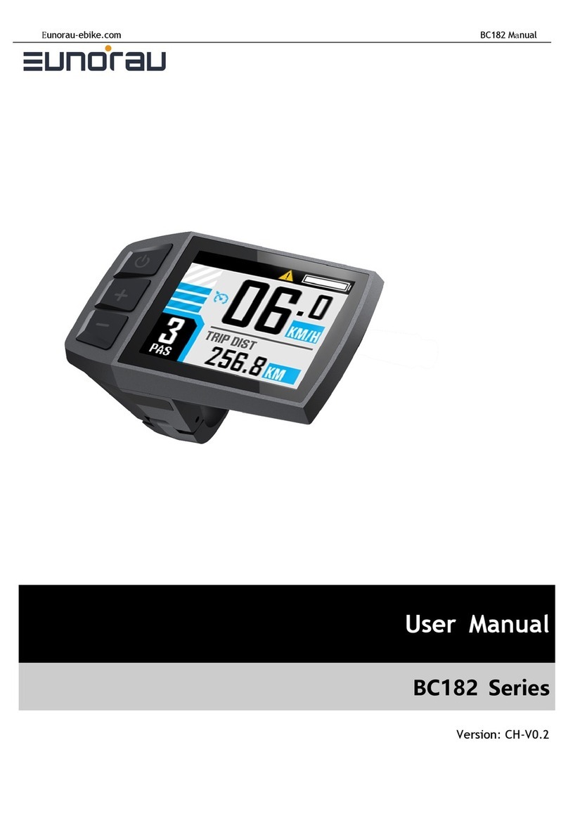
EUNORAU DM01 Reference manual

2
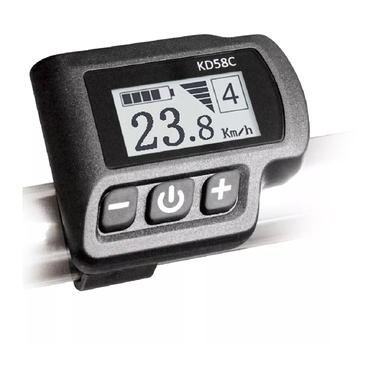
DM01 Display
Functionality Introduction
Product Name:Intelligent LCD display
Part Number:DM 01

3
Content
A. Product introduction.............................................................................................................. 6
1. Product name and model ................................................................................................... 6
2. Product Introduction .............................................................................................................6
3. Range of application ............................................................................................................6
4. Appearance and size............................................................................................................6
5. Display coding rules .............................................................................................................7
B. Product manual............................................................................................................................ 8
1. Specifications ....................................................................................................................... 8
2. Function overview.................................................................................................................8
3. Installation ............................................................................................................................. 9
4. Interface..................................................................................................................................9
4.1 Boot interface................................................................................................................ 9
4.2 Basic interface and operation...................................................................................10
4.3 Function interface introduction.................................................................................11
Boot interface and basic function interface ........................................................... 11
Other function interface ............................................................................................... 11
Setting interface ............................................................................................................ 13
5. Button defination ................................................................................................................ 15
5.1 Button name:............................................................................................................15
5.2 Defination of button operation:.................................................................................15
6. Basic function operation ....................................................................................................16
6.1 Turn on/off the display............................................................................................... 16
6.3 Information switch ..................................................................................................... 16
6.4 Light control function ................................................................................................ 17
6.5 Speed information switch ........................................................................................ 17
6.6 Walk assist function .................................................................................................. 17
6.7 Battery power indicate and the assist power output.............................................18
7. Setting function ...................................................................................................................19
8. Data clearance.................................................................................................................... 21

4
9. Error information................................................................................................................. 22
10. Wire defination................................................................................................................ 23
10.1 Standard wires definition: ...................................................................................... 23
10.2 Standard conversion wire specifications:.......................................................... 24
C. Package specifications................................................................................................................24
D. Note ...............................................................................................................................................25

5
A. Product introduction
1. Product name and model
LCD display for electric power assist bikes
Model: DM01
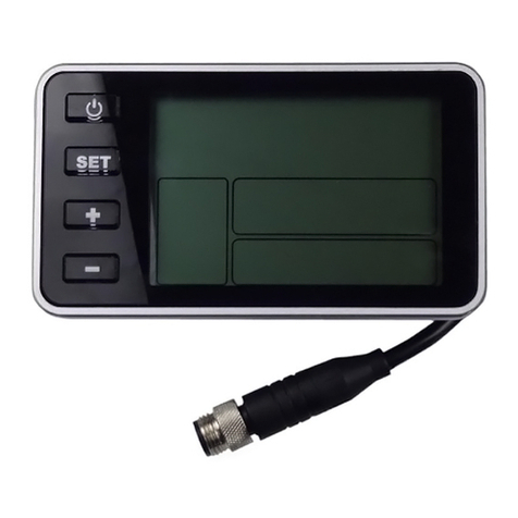
2. Product Introduction
IMD craft,2.5D chamfer, 4H extra hard glass screen
B/W contrast, 1.3-inch VA segment LCD
Integrated one-piece button, perfect hand feeling
Excellent outdoor design, IP65 waterproof level
Waterproof serial port, convenient maintenance
Following functions are optional, please consult our sales team for more details
Standard USB(Type B)charger port, charge current 800mA
Bluetooth function
3. Range of application
Suitable for electric power assist bicycle in accordance with the standard of EN15194:2017
4. Appearance and size
The material of product shell is PC+ABS. And the material of the window is
applying high hardness IMD craft, 2.5D chamfer. Adapt to assembled on φ22.2mm
handlebar.

6
68.5mm
41.3mm
42mm
5. Display coding rules
As shown as above picture,
Production serial number
Manufacture year and week number
Manufacture factory code, M1, M2, M3
Hardware version number, C-CAN, U-UART,
last 2 numbers means version(may omit)
Product model

7
A08.01-36V2570XX
Parameter character value (reserved)
Parameter character value (wheel size
value, 700C=70, 27.5=27)
Parameter character value(speed limit
information, range from 04 to 46
arameter character value
voltage , 24/36/43/48/52 , can be expanded
)Customer software version number
(may omit) Customer code
B. Product manual
1. Specifications
①Power supply: DC 24V/36V/48V
②Rated current: 12mA
③Shutdown leakage current : <1uA
④Screen specification:1.3” VA segment screen
⑤Communication method: UART/ CAN-BUS 2 modes
⑥Operating temperature: -20 °C ~ 60 °C
⑦Storage temperature:-30 °C ~ 80 °C
⑧Waterproof level:IP65
2. Function overview
①Five buttons, separated walk assist button, good hand-feeling
②6 power assist level
③Km / miles
P
C
(

8
④Speed display: Real-time speed,maximum speed,average speed
⑤Battery power indicate in percentage and levels.
⑥Endurance mileage indicate
⑦Headlight on/off status indication and control
⑧Mileage indicate: Subtotal mileage (TRIP), total mileage (ODO)
⑨6km/h walk assist function
⑩Parameter setting function
⑪Error code indicate
* Charge function and bluetooth are optional
3. Installation
①Open the display lock clip, set the display in the left handlebar (standard
handlebar size:Φ22.2).Adjust to a position easy to operate tighten and fix the screw by M3
hexagon. Tightening
torque: 0.8N.m.
*Note: Damage caused by excessive torque is not covered by the warranty.
②display connected with controller by 5 pin connector as required drawings.
4. Interface
4.1 Boot interface

9
Boot interface, after turn on the display for 2 seconds, all segments of the display are
on. After communication build, display gets the assist level information, TRIP/ODO
information and so on.
Show the real-time information from controller.(information can be customized).
4.2 Basic interface and operation
Light indicate
Diagnosis tool connection
indicate
Function information area
Data information area
M button
Power assist level
Walk assist button
①Power indicate:Display communicate with BMS to get the battery power information and
show
the information as protocol. Information including percentage and levels.
②Current speed and unit: show the current riding speed, default unit is KM/H, accurate to
one after
the decimal point.
③Trip and ODO: default unit is KM, accurate to one after the decimal point, maximum Trip
value is 9999, maximum ODO value is 9999;
④Error information: show error icon , and show the error code accordingly in the fnction
area.
⑤6 power assist levels, including off level, off means no assist power.
⑥light indicate: when there is light on the bike and the status is on, show light indicate icon
Power button
Adjust up
Battery power indicate

10
4.3 Function interface introduction
Boot interface and basic function interface
After display turn on, the segments will all turned on for 2 seconds, display communicate
normally and enter the basic function interface.
Display get the assist level information from controller and get BMS information from battery.
Others are real-time information.
Other function interface
Trip indicate
Show TRIP icon on the top middle area as below picture, 4 digit show the trip value,
accurate to one after the decimal point, when trip value exceed 999.9, show without decimal
point.
Maximum value is 9999KM. When the value exceed 9999KM,keep the last 4 numbers.
Trip miles doesn’t show unit. The unit mode is the same as the speed, and can be set in the
system unit setting.
ODO indicate
Show ODO icon on the top middle area as below picture, 4 data to show the ODO value,
accurate to one after the decimal point, when trip value exceed 999.9, show without decimal
point.

11
Maximum value is 9999KM. When the value exceed 9999KM, keep the last 4 numbers.
ODO value will need service tool to do the clearance. ODO miles doesn’t show unit. The unit
mode is the same as the speed, and can be set in the system unit setting.
Endurance mileage indicate
Display reads the endurance mileage information from controller and show after
the RANGE icon on the top. 4 digit to show the range value, accurate to one after the
decimal point, maximum
999.9KM
Average speed indicate
Show the average speed in current trip, maximum 99.9KM/H
Max speed indicate
Show the max speed in current trip, maximum 99.9KM/H

12
Error code indicate
icon according to the information get from the system. And show
Detailed error code in the function area and blink in 1Hz. When the error code indicated,
display will not show ODO ,TRIP ,RANGE icon and other functions are normal. Motor will
act according to the error information. Interface shown as below:
Setting interface
Within 10 seconds turned on the display, long press M button to enter setting
interface. Short press 、to switch items loop. Short press M to confirm the item be
chosen. When item chooses, the icon will blink in 1Hz. In the setting interface no matter
which setting item, short press 、to choose the parameter to set, long press M to
confirm the parameter. In the setting interface no matter
which setting item, long press M to save the parameter and back to up level page.
Short press button, the interface will show as below to set then to read information status,
press
can go back to previous item:
Display show the
Short

13
Unit setting interface
Backlight level setting
interface
Sleep time setting interface
Unit setting interface Speed limit setting interface Wheel size setting
interface
The interface of the settings above check part 7 for the operation for the setting function
operation.

14
5. Button Definition
5.1 Button name:
Power button
Adjust up
mode
Adjust down
Walk mode
Power button: Turn on/off the display
Adjust button: adjust the assist power level while riding and setting function when
setting operation.
Mode button: function interface switch and enter to parameter setting interface.
Walk mode button: activate the walk assist function
5.2 Definition of button operation:
Operatio
n type
Description
Short press
Press the button and soon released, while the button is released,the
function activated accordingly.
Long press
Press the button and hold,when the hold time exceed the
setting time(generally 2 seconds), the function activated
accordingly.

15
6. Basic function operation
6.1 Turn on/off the display
When the display and controller connected well, long press button when
display is off, display will show boot interface then enter the basic interface and work.
Long press button when display is on, then display will be turned off. If no operation
on the display for the time setting exceed the sleep time, display speed is 0, and current to
display lower than 1A, display will be turned off automatically.
6.2 Assist level switch
Short press 、button to switch assist level, and change assist mode, there are 6
levels.
icon will show still. 1-5 levels, and off level.
short press
short press
the assist level will not loop. That means when the level gets to level 5, it will need to
Press button to get to OFF level. It’s the same when adjust up.
6.3 Information switch
Short press M button when display is on, information will switch from
TRIP,ODO,RANGE ,information switch loop. TRIP/AVG->ODO/MAX->RANGE. When
speed is not 0, the data area have not show the speed, no operation on M button for 5
seconds, display gets back to the speed interface.
Interface switch as below when press M button:

16
*if the system without the RANGE information from BMS, display will not put the RANGE on
the screen.

17
6.4 Light control function
When the ebike is on with battery, long press button to turn on the front light, at the
same
time, the light icon show on the screen to indicate light on status. Long press button to
turn the lights off.
6.5 Speed information switch
In basic function interface, display show the real-time speed, average speed, max speed
and mileage information switch. Check 6.3 for the information switches.
6.6 Walk assist function
When speed is 0, long press button to enter walk assist mode, motor output
according to the setting speed, display show the walk assist icon and the real-time
speed. PAS level show as follow . Release button or any
other button pressed system will get out of walk assist mode, motor turns off, display get
back to the basic function interface. The interface show as below:

18
6.7 Battery power indicate and the assist power output
Battery power information show the battery level and percentage. The battery are 5
levels according to the battery capacity.
When the battery capacity is lower than 5% or the voltage is lower than under
voltage, display will enter under voltage mode. In this mode battery level showed level 0
and border blink at 1Hz. No power output from the motor. Assist level switch disabled,
adjust button disabled. Power assist level show . Display will get out of low-
voltage mode after reset, when the voltage is above
Under voltage value and battery capacity is above 5%.
Percentage of battery power(C)and power level table(need BMS or controller to
provide the
percentage of the battery)
SOC
Battery level
Description
80% ≤ SOC
Full battery level 5
60% ≤ SOC < 80%
Level 4
40% ≤ SOC < 60%
Level 3
20% ≤ SOC < 40%
Level 2
10% ≤SOC < 20%
Level 1
5% ≤ SOC < 10%
Level 0
0% ≤ SOC < 5%
Level 0 and icon blink at 1Hz
● Remark about battery indicate:
When there is a battery communication error:
1. Display will estimate the power according to the voltage and show the battery level
accordingly;
2. No battery percentage information shown
3. Range information show hypen - - - -

19
4. When the voltage is lower than the under voltage(considering the current influence the
voltage, change to the voltage value when the current is 0).
Before communicate build after turn on the display, display will not show battery percentage
information. Battery bar show full level and blink at 2Hz. When the battery information read,
battery bar stop blink and show the percentage information. If communication have not built
successfully, battery bar will stop blink and not show the percentage information.
7. Setting function
Display provides specific parameter setting function. The optional items of setting
function will be deleted according to different market and product standards. The
following is the complete parameter setting, information reading function description
under the default state of display. Please
contact our sales and technical support team for confirmation in case of any discrepancy.
10 seconds within display turned on, long press M button, display enter the setting
interface. Short press M to confirm the choosing of items. When the item picked, the current
selected parameter blink at 1Hz. In any interface of the setting mode, short press ,
to select the parameter, short press M to confirm the parameter. In any interface of the
setting mode, long press M to save the parameter and get back to the up level interface. In
any grade of the setting mode, short press M button to enter
each setting interface.
The first setting interface is the system unit parameter setting.
Unit
setting
UNT=Unit
Value=KM/H
MPH
Default
Value=KM/H
KM/H—Metric
MPH—
Imperial

20
Backlight
level
setting
BLG=Back
light
Value= 1,
back light
level 60%
Value= 2 back
light level
80%
Default
Value= 1

21
Value= 3 back
light level
100%
Auto
shutdow
n time
SLP= Auto
sleep
Value=0-30
min
Step=5 min
0 means
display
will not
auto
shutdown
Wheel size
setting
DIA=Wheel
diameter
Value= 12,
14,16,
20,24,
26,27,
27.5,28
,700C,
29,CCF
(Default
unit,
inch)
Default
value=26;
*when
value=CCF,
customer can
enter wheel
circumference
value (mm)
. Check detail
information
below.
Speed
limitation
setting
SPD=Speed
limitation
Value=5-
46,step
value is 1,
unit is
km/h 。
Default:25
Display
Software
version
DPS=display
software
version
Value= fixed
value
Read only
* Note:wheel size setting will need the support information from controller’s
communication protocol.
When wheel size setting choose CCF value, allow user to define the wheel’s Circumference
value of the system.(Four digit length value ,unit mm).
Long press M to select CCF, data area blink [[F icon,at the sametime function area
, The thousandths field blink, short press 、button to switch parameter,
Table of contents
Other EUNORAU Bicycle Accessories manuals
