EUNORAU CDE8 User manual

Preface
CDE8 specification
Eunorau E-Mobility USA Corp

Eunorau E-Mobility USA Corp
Page 1of 9
To ensure better performance of your e-bike, please read through the CDE8
inspection carefully before using it. We will inform you of all the details, including
the installation and setting of the hardware and normal use of the display with the
most concise words. Meanwhile, the specification will also help you solve possible
malfunction.

Eunorau E-Mobility USA Corp
Page 2of 9
Contents
1. Product introduction ..........................................................................................3
2. Function introduction .........................................................................................4
3. Button definition ................................................................................................4
4. Operating instruction .........................................................................................5
a.Power on/off......................................................................................................5
b. Level to adjust ....................................................................................................5
c. Turn on/off light .................................................................................................5
d. Implement function............................................................................................5
e. Battery power indication ....................................................................................5
5. Cable outlet instruction ......................................................................................6
6. Quality assurance and Warranty scope ...............................................................8
Warranty................................................................................................................8
Other items ............................................................................................................8
7. Error code definition table..................................................................................9
Eunorau E-Mobility USA Corp
Page 3of 9
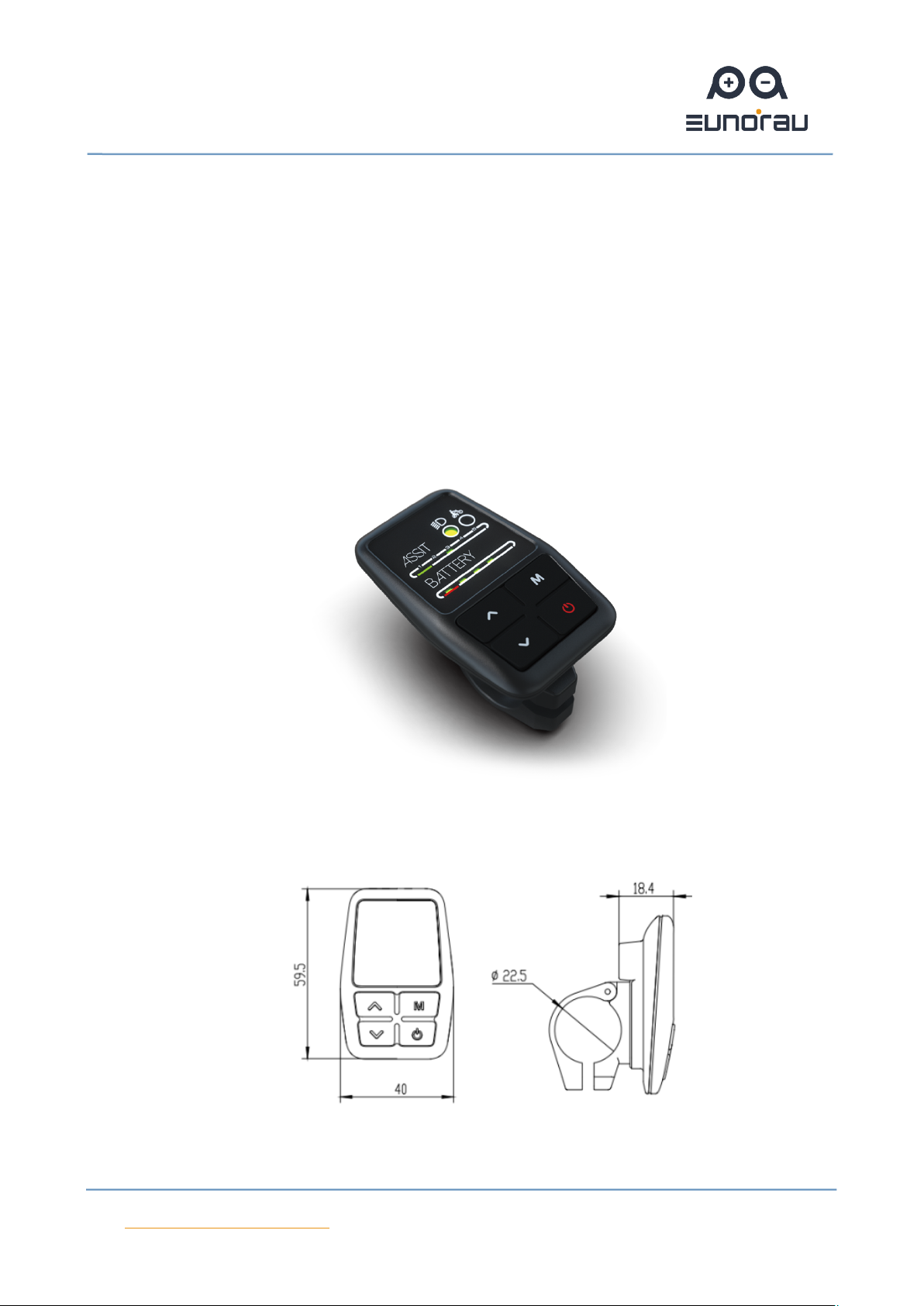
1. Product introduction
CDE8 products use the LCD screen, double side printed board, nylon buckle,
ABS material shell, and dip plastic parts. Under the temperature ranging from -20℃
to 60℃, the shell material can ensure the good mechanical performance of the
products.
Real product and dimension (unit: mm)
Figure 1
Figure 2
Eunorau E-Mobility USA Corp
Page 4of 9
2. Function introduction
CDE8 is a multi-function LED display. The main functions include the power
switch, battery power indication, level indication and adjust, and headlamps switch
function. With another CDBL_C product of our company will greatly simplify the
handlebar cable.
This display can be used at the left or right sides, strong compatibility.
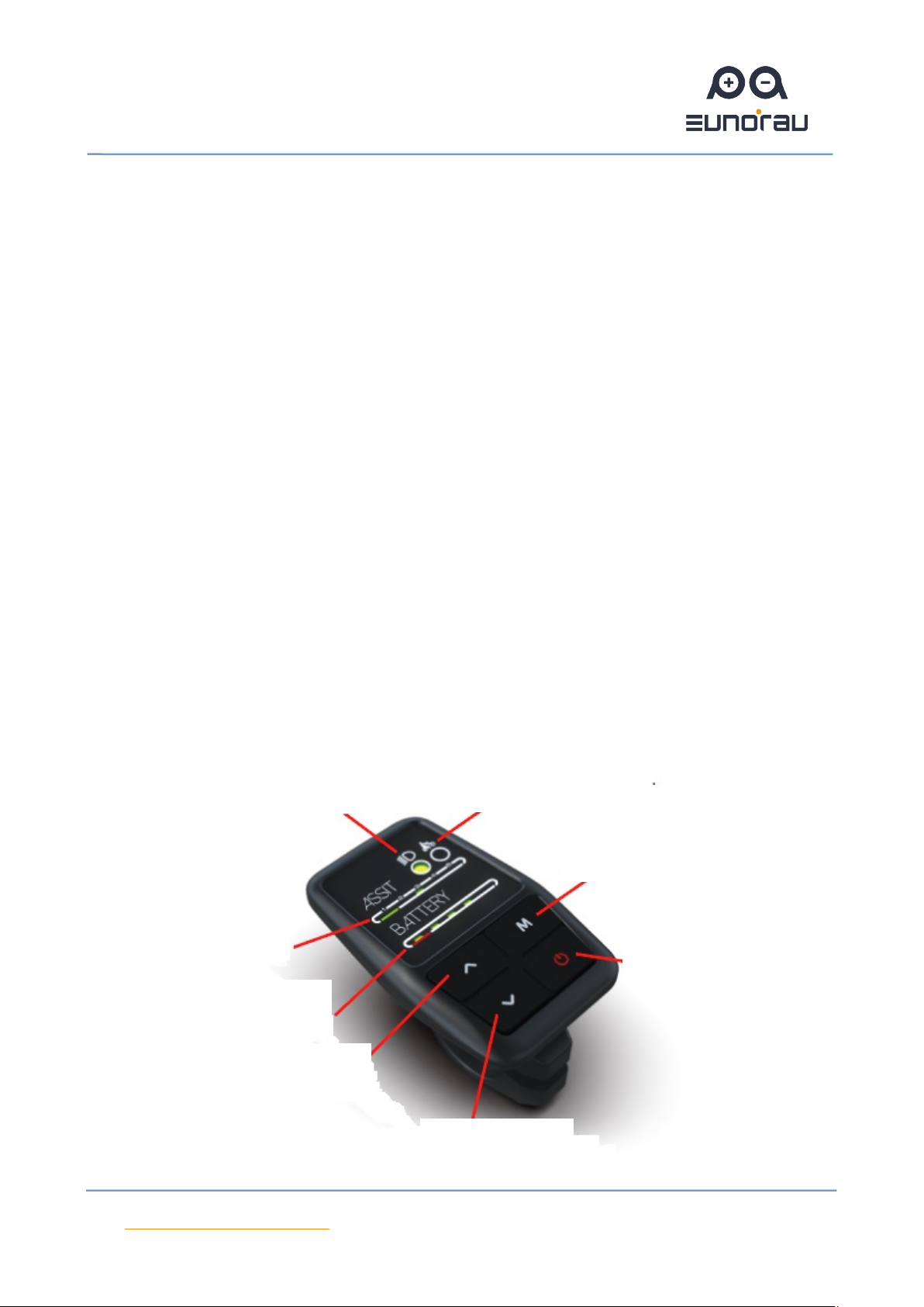
3. Button definition
CDE8 has 4 buttons totally, including POWER button (headlight power button),
UP button, DOWN button and M button (6Km/h implement button). In addition,
there are 5 led lights on each row to show the battery power and level. And there is
one indicator light of the 6km/h implement function and one indicator light of
headlight, as shown in figure 3.
Indicator light
of headlight
Indicator light of 6Km/h
implement function
Button for 6Km/h
implement function
Power button/
headlight button
Level
indicatio
n
Power
indication
Up button
Down button

Eunorau E-Mobility USA Corp
Page 5of 9
Figure 3
4. Operating instruction
a. Power on/off
At the off state, clicking button can turn on the display; And then press
button for 3 seconds will power off the display.
b. Level to adjust
After power on the display, when the first LED lighten in the ASSIT row, it
means level 1; Clicking UP button to lighten the second LED, means level 2; Similarly,
click UP button again, and the third LED is bright, indicating that it is level 3, and the
highest can be level 5.
c. Turn on/off light
Clicking button can power on the headlight, and the indicator light of
headlight will be bright. Click the button again, it will power off the headlight and
the indicator light is light off.
d. Implement function
Long pressing button will be 6km/h implement function, and the indicator
light will be lit up.
e. Battery power indication
Eunorau E-Mobility USA Corp
Page 6of 9
LED light in BATTERY row means battery power indication. When the LED shows
the last bar, means the power is too lower, you should charge your e-bike
immediately.
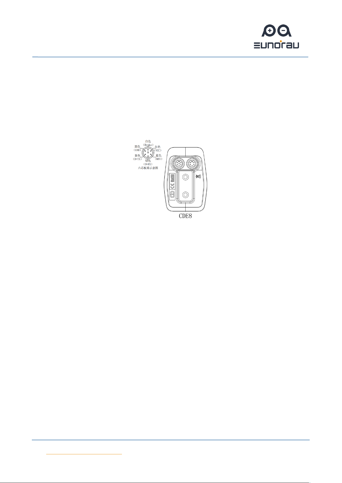
5. Cable outlet instruction
Figure 4
6. Quality assurance and warranty scope
Warranty:
A. Under warranty, our company will shoulder the responsibility to provide
limited warranty to any faults caused by the quality of the product under normal
use.
B. The warranty period lasts for 18 months since the date of purchase.
Other items:
The following items does not belong to warranty scope
A. Disassembly or modification without authorization.
B. Malfunction or damage caused by the misuse or improper installation and
debugging by the users or the third party.

Eunorau E-Mobility USA Corp
Page 7of 9
C. Shell scratch or breakage after leaving the factory.
D. Wiring scratch or breakage.
E. Malfunction or damage caused by the force majored (fire, earthquake etc. )
or natural disasters (lightening etc.)
F. Beyond Warranty period.
7. Error code definition table
error code
definition
2
Over current protection is checked by the controller. Check
whether the connectors of three-phase power cable and the hall
signal connectors are badly connected. There is something wrong
with the controller or motor if the problem is still present after
reconnect the connectors.
3
The controller can’t properly drive the motor: Check whether
the connectors of three-phase power cable and the hall signal and
the power supply connectors are badly connected. Or there is not
enough power to drive the system than 2S, such as climbing or the
wheel is stuck . There is something wrong with the controller or
motor if the problem is still present after reconnect the
connectors.

Eunorau E-Mobility USA Corp
Page 8of 9
4
Battery voltage is too low to protect, under voltage protection.
5
After the system power on, check whether the brake is working
properly. If the brake signal is less than 0.75V for very a long time,
there is something wrong with the brake.
6
Check whether the hall commutation signal of the motor is
faulty or not. Check the connector of the motor’s hall signal cable
is disconnected or not. The hall of motor maybe broken if the
problem is still present after reconnect the connectors.
7
After the system power on, check whether the throttle is out of
control or the throttle signal is less than 0.75V, or customer turns
the throttle before the system works, the error can be solved after
throttle is reset.
8
The controller is broken.
A/10
The display and the controller have communication problems,
the yellow cable is not connected.
D/13
The controller program is wrong or the 5V is wrong, check
whether the brake signal short with 5V.
F/15
The display and the controller have communication problems,
the green cable is not connected, or the communication protocol
doesn’t match.

Eunorau E-Mobility USA Corp
Page 9of 9
If there is something wrong with the 5 cables between the controller and display:
(1) If the display can’t power on and there is no display on the screen, the
reasons may be: the power supply connector between controller and battery is not
connected well or there is something wrong with the cable (the red, black ,blue
cable of any 1 cables) between display and controller.
(2) If the display is turned on, but after working 3 seconds stop working. The
reasons may be: the connection (the green, yellow cable) between the display and
the controller is open circuit.
The error code explanation is based on the correct system from
Eunorau E-Mobility USA Corp
Table of contents
Other EUNORAU Bicycle Accessories manuals


Popular Bicycle Accessories manuals by other brands

Nashbar
Nashbar Deluxe User instructions

Cycle2Charge
Cycle2Charge Cycle2Charge User Manual, Mounting Instructions

Specialized
Specialized Command Post Adjustable Height Seat Post installation guide

moon
moon Arcturus Auto User guideline

VDO Cyclecomputing
VDO Cyclecomputing R4GPS Short manual

Hayes
Hayes CX Series Installation


