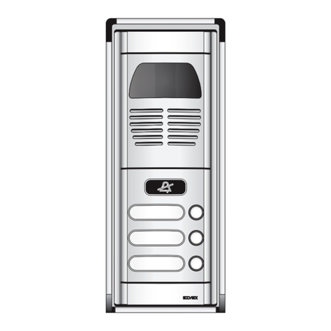
EURA VDP-22A3 PLUTON G User manual

VIDEO DOORPHONE
User Manual
VDP-22A3 PLUTON G

2
TABLE OF CONTENTS
1. DEVICES CONSTRUCTION...........................................................................................3
2. DEVICES INSTALLATION.............................................................................................4
2.1. INDOOR MONITOR INSTALLATION ...................................................................4
2.2. OUTDOOR VIDEO DOORPHONE INSTALLATION ...........................................5
3. WIRING DIAGRAM........................................................................................................6
4. USINIG VDP-22A3 VIDEO DOORPHONE ................................................................ 7
4.1. TALKING WITH VIEW ...........................................................................................7
4.2. PREVIEW FUNCTION ..........................................................................................7
4.3. GATE OPENING FUNCTION. ...............................................................................7
5.CONNECTING VDP-22A3 WITH ADDITIONAL UNIPHONE ....................................8
6. TECHNICAL DATA........................................................................................................11
INITIAL REMARKS
Before assembling, wiring and setting up of device the user should carefully read gi-
ven manual. In case of any troubles with understanding the content the user should
contact the producer.
Unassisted assembling and start of the device can be done only with the use of proper
tools. However, it is highly advised to set up a device by qualifed personnel.
The producer is not responsible for damages made during incorrect set-up or mainte-
nance or in case of any unassisted repairs or modifcations.

3
1. DEVICES CONSTRUCTION
The VDP-22A3 Video doorphone set consists of:
- VDA-02A3 indoor unit (monitor) for home installation,
- VDA-10A3 outdoor unit (video doorphone camera) for outdoor installation,
- DC power supply,
- accessories (rain cover).
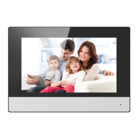
This monitor is equipped with a 7 inch color LCD display. In addition to the standard
communication functions with the visitor, the camera preview and controlling the en-
trance to the property, the monitor can controls the second entrance. The adjustment
knobs allow you to regulate the volume of conversation, brightness and saturation.
By using the button above them, the user can select of the 8 available chime melodies.
It is possible to power the set alternatively - DC 12V DC from a DIN rail mounted power
supply.
MONITOR CONSTRUCTION
1. TFT LCD Color display
2. Microphone
3. Speaker
4. Previewbutton
5. Unlock button
6. Second gate unlock button
7. Talk button
8. Wiring terminal
9. Wiring terminal
10. Mounting Hooks
11. Talking volume
12. Contrast
13. Brightness
14. Melody selection button
15. Melody volume selection switch
16. Bracket for wall mount
Fig.1
Fig.2
Fig.3
Fig.4

4
2. INSTALLATION
CAUTION!
Recommended length and cross-sections of cables connecting both modules:
0 - 50m 4x0.5mm2
50m - 100m 4x0.75mm2
The connection to the electromagnetic bolt should be
carried out by 2 x 1 mm2 cable, similar to the connection to
the optional gateway automat. The optimum solution will
be to use one 4-wire connecting the monitor to the external
module, one 2-wire cable connecting the monitor to the electromagnetic lock and one
2-wire cable connecting the monitor to the gateway automat. If you have other
connection wires than the recommended one, then you are allowed to use them, but
you must test the wiring to verify that it works.
2.1. INDOOR MONITOR INSTALLATION
To properly install indoor monitor you should:
1. Use the screws to x the Mounting Bracket on the mounting box (g. 2a), in a way
that provides easy and aesthetic connection for the power cord and connection wi-
res. The standard height at which the monitor screen should be stand on the frame
is approximately 145cm, but its position can be adjusted to the individual needs of
the user.
2. Connect the system wiring according to the graph presented in fg. 10.
3. Connect the power cord (g. 2) from the delivered power supply.
OUTDOOR VIDEO
DOORPHONE CONSTRUCTION
1. Camera
2. Speaker
3. LED light
4. Call button
5. Microphone
6. Mounting holes
7. Connection terminal
8. Rain shade
Fig.5 Fig.6
Fig.7

5
4. Mount the monitor on the 4 bracket mounting hooks
5. Plug in the power supply ~230V/50Hz.
2.2. OUTDOOR VIDEO DOORPHONE INSTALLATION
The outdoor unit is factory adapted for surface mounting.
CAUTION!
The proper location of the outdoor video doorphone unit determines the comfort
of working with it. Before making the mounting holes it is recommended to expe-
rimentally select the location for the outdoor module. For this purpose, rst install
the monitor indoor unit and connect it with the outdoor unit - it should be hold by
another person for the testing time. Then connect the power supply and choose a
proper place to mount the outdoor unit. The person holding the outdoor module
simulates the normal operation of the device and calls the other person by pressing
the button. At this time the person with the monitor unit should observe the eld
of view of the camera. The person who hold the camera module, based on the sug-
gestion of his or her partner, must position the camera module in optimal position.
This location must be marked and only then you could perform the mounting holes.
50 cm
46o
50 cm
50 cm
150-160 cm
34o
WARNING!
If the module is installed in a place that is not protected against rain, it is necessary to
install a cover over the module which will prevent the water from penetrating into it.
DAMAGE CAUSED BY FLOODING THE MODULE IS NOT COVERED BY THE WARRAN-
TY.
Fig.8

6
WARNING!
Do not make any wire modication while the unit is connected to the power. Failure
to observe this precaution could result in damage to this device! Before installation
or disassembling the unit, disconnect the power supply rst!
Practical tips for mounting the camera module
Avoid places where the camera lens is exposed to the direct light (sun, reections,
street lighting), because this may cause malfunction and weaken the visibility.
Other mounting methods
The manufacturer does not recommend other than described in this manual installa-
tion methods, but qualied installers may make the necessary changes.
3. WIRING DIAGRAM
Fig. 10 shows the wiring diagram of: outdoor unit with camera, indoor unit, electric-
-lock, optional outdoor gate and power supply.
Fig.8
Fig.9
To properly install outdoor station:
1. Unscrew the lower xing screw and separate
the outdoor unit from the rain cover.
2. With 3 holes in the bottom of the protective
roof, uncheck on the wall the places for moun-
ting pins (g 9).
3. In the marked places, drill 3x Ø5mm mounting
holes and place there 3 xing pins (g. 9).
4. Using 3 mounting screws, secure the rain co-
wer to the wall (g. 9).
5. Connect to the unit 4-wire from the monitor
(g. 9).
6. Place the outer module cassette in the previo-
usly secured rain cover and tighten the bottom
xing screw, in a way not to destroy the inter-
nal elements.
Fig.10

7
CAUTION!
Control of the entrance gate is realized by relay whose contacts N.O. (Normally open)
are output to terminals 7 and 8 of the monitor.
CAUTION!
All power and communication wire that have a direct contact with the wire used to
connect indoor and outdoor unit could cause malfunctioning.
4. USINIG VDP-22A3 VIDEO DOORPHONE
4.1. TALKING WITH VIEW
4.2. PREVIEW FUNCTION
It is possible to discreetly watch what is happening in front of the gate without a call
from the outside. Start this function by pressing the preview button. At this point, a pre-
view image is displayed on the monitor, which will disappear automatically aer approx.
40 seconds. During this operation, the outdoor module speaker remains o.
4.3. GATE OPENING FUNCTION
In addition to the remote opening of the front door or entrance door, the VDA-22A3
also oers a possibility to control the outdoor gate to the property or garage door. If
you have an ATM installed in your premises, you can connect a video door phone to
the machine’s control input and then start the gate drive using the front panel button.
Terminals 7 and 8 are used to connect the gate drive on the back of the monitor (g.10).
Terminals 7 and 8 are N.O type relay outputs (Normally Open), so the door operator
should also be able to trigger a short short-circuit of the input terminals (N.O.). On the
market, most of the gates are equipped with this type of control input. In this case
terminals 7 and 8 back of the monitor simply connect in parallel with the entrance
At the moment when guest presses the
call button on the outdoor unit (g. 11), the
chime signals and the image on the indoor
unit (monitor) automatically appear. When
you press the talk button, you can talk
with the guest (g. 12). The person inside
the room has the possibility to open the
door remotely (releasing the electroma-
gnetic bolt) by pressing the button on the
monitor or remotely activate the outdoor
gate. The Talk function with the preview
will be activated for 2 minutes, aer this
time the unit will return to standby mode.
To continue the conversation, press the
Talk button on the monitor again or press
the button: preview and talk on the indoor
unit. Appropriate picture brightness, color
saturation, talk volume and chime melody
can be set with potentiometers and swit-
ches.
Fig.11
Fig.12

8
button inside the property, to manually run the gate drive. It is possible to connect to
the terminals 7 and 8 of the standard electromagnetic lock, to open the second gate to
the property (g. 13). Then, a separate power supply with parameters adjusted to the
parameters of this bolt should be used for powering the bolt. Release of the second
additional bolt takes place aer pressing the door release button.
Fig. 13. Wiring diagram
5.CONNECTING VDP-22A3 WITH ADDITIONAL UNIPHONE
Fig. 14 presents elements of VDP-22A3 set connected with the ADA-30A3 uniphone.
Fig. 14. Wiring diagram

9
CAUTION!
1. The electric-lock can be opened by uniphone and monitor, provided by the proper
polarity with electric-lock power supply.
2. When called from the outdoor video doorphone, the signal is triggered simul-
taneously in the monitor and uniphone. When you press the Talk button on the
monitor, the uniphone continues to emit a chime signal - until you li the handset
or automatically switch o the chime (aer three beeps). Similarly, when a call is
received by liing the handset - the monitor will continue to ring the chime until
the answer button is pressed or the chime is automatically deactivated (aer three
beeps). If you receive a call between both devices - both calls are in progress, so each
user can join the ongoing call.
3. Separate power supply for monitor and uniphone is obligatory.
4. The set can be expanded up to 1 monitor, 1 uniphone and 1 outdoor video door-
phone.
5. The second button of the uniphone can run the second electric-lock / gate. It is
also possible to connect a second electric-lock / gate to a uniphone and monitor
simultaneously.
CLEANING
Clean the monitor with a so cloth. Do not use detergent, thinner, volatile or corrosive
liquid.
CAUTION!
Using cleaning substances based on solvents, gasoline etc. and abrasives materials
is not permitted!
If the button on the video doorphone unit is locked, clean it with a penetration-
preservative spray (eg. WD-40). The spray should be sprayed on the button and
le to dry.

10
BEFORE YOU CALL - TROUBLE SHOOTING
No Picture / Signal Solution
No Picture / Signal - Make sure all the connection are secure and
properly connected.
- Make sure your monitor is plugged into a po-
wer source.
- Make sure there is nothing obstructing the
view of the camera.
No Picture, but intercommunication is
normal - Make sure all the connection are secure and
properly connected.
- Make sure there is nothing obstructing the
view of the camera.
No audio when calling - Make sure the volume noch on the indoor
unit is tuned up.
- Make sure there is nothing interfering with
the speaker or microphone on the indoor unit
or the camera.
- Make sure all the connections are secure and
properly connected.
The outdoor unit cannot call the indoor one - Make sure all the connections are secure and
properly connected.
No one can hear me outside but I can hear
them when calling - Press TALK key for two-way intercom.
- Make sure all the connections are secure and
properly connected.
No one can hear me outside but I can hear
them when monitoring - Press TALK key for two-way intercom, since
simple touch MONITOR allows you to see and
hear outside but prevents the outside from
hearing you.
- Make sure all the connections are secure and
properly connected.
w

11
7. TECHNICAL DATA
Set
System EURA Connect
Monitor unit VDA-02A3
Video doorphone unit VDA-11A3
Power supply VZA-63A3
Working Voltage 12 V DC
Video signal 1Vp-p 75 Ohm CCIR
Connecting wire 4
Number of apartments 1
Number of supported inputs 2
Intercom No
Expansion Yes
Monitor VDA-02A3
Monitor power consumption - standby /
working 2 W / 5 W
Monitor screen Colour TFT-LCD
Screen size 7”
Resolution 480 × 234 pixels
Touchscreen No
Number of relay outputs 1
SD / micro SD card slot No
Images internal memory No
Movies recording No
Ring tone 8
Loudspeaker Yes
Menu language No
Digital frame function No
Monitor working temperature 0ºC ~ +30ºC
Monitor size (H x W x D) 160 x 240 x 17 mm
Monitor weight 0,85 kg
Video doorphone unit VDA-10A3
Unlock power output No
Video doorphone power consumption -
standby / working 0,2 W / 5 W
Resolution 700 TVL
Camera angle of view (horizontally) 55º
Camera Color CMOS 1/4’’
Activation time for elctromagnetic lock 3 sec
Housing material Aluminum
Number of relay outputs No
Video doorphone installation Surface mounted
Positioning possibility of the camera eye No
Night view LED 6 LEDs (white light)
Proximity reader No
Keypad No
Fingerprints scanner No
Rain cover Yes

12
Water proof rating IP44
Video doorphone working temperature -18ºC ~ +50ºC
Video doorphone size (H x W x D) 144 x 64 x 52 mm
Video doorphone weight 178g
EURA-TECH Sp. z o.o.
84-200 WEJHEROWO, ul. Przemysłowa 35A, POLAND
www.eura-tech.eu
All rights reserved.
Pictures, graphs and texts are the property of “Eura-Tech” Sp. z o.o.
Copying, distributing and publication without permission of author is forbidden.

EURA-TECH Sp. z o.o.
84-200 WEJHEROWO, ul. Przemysłowa 35A, POLAND
www.eura-tech.eu
All rights reserved.
Pictures, graphs and texts are the property of “Eura-Tech” Sp. z o.o.
Copying, distributing and publication without permission of author is forbidden.
EU Conformity Declaration of this device is available on
http://www.eura-tech.eu website
Table of contents
Other EURA Intercom System manuals
Popular Intercom System manuals by other brands
Aiphone
Aiphone MY-1CD Installation & operation manual
PS Engineering
PS Engineering PMA450A Pilot's guide and operation manual

Motostar
Motostar LIVIMN-B installation manual

Autocop
Autocop VT2000 series user manual
Extel
Extel 720321 manual
International Electronics
International Electronics Oracle 607 manual
