TCS AMI Series User manual

TCS TürControlSysteme AG, TCS Hotline Deutschland: 0 41 94 / 9 88 11 88 Subject to technical changes.
Fax: 0 41 94 / 9 88 129 E-Mail: info@tcs-germany.de PI_AMI11100-uk 1A
Product information
Series AMI
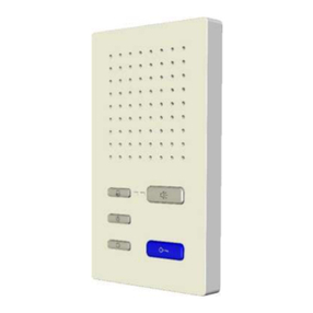
Built-in door loudspeaker module
AMI11100
Note on the validity of this product information
This product information states specific information on the module.
It is only valid in combination with the enclosed product information Modules of the series
AMI in front-door stations.

2 01/2013
TCS TürControlSysteme AG, TCS Hotline Deutschland: +49 (0) 41 94 / 9 88 11 88 Subject to technical changes.
Fax: +49 (0) 41 94 / 9 88 129 E-Mail: hotline@tcsag.de PI_AMI11100-uk 1A
Scope of delivery
1 x Built-in door loudspeaker module AMI11100
3 x Spacer foil 0.5 mm
1 x 4-pin connecting cable
4 x Securing nut M4
1 x Screwdriver with round handle
Product information built-in door loudspeaker module AMI11100
Product information modules of the Series AMI in front-door stations
Intended use
The built-in door loudspeaker module AMI11100 is a module for front-door stations of
the sereis AMI.
It can be used in combination with other modules of the series AMI (except for function-
al group dispaly modules).
Short description
Connection for bell button module via 4-pin plug connector
Voice-controlled hands-free talking (standard)
Full duplex hands-free talking can be activated for indoor stations with handset
2 indoor stations can be allocated to any bell button provided on site
Error detection and display
Volume and volume acknowledgement tone can be adjusted manually
Pluggable memory to replace front-door stations identical in construction
Further slot to read-in TCU2 memory
R-terminal to extend functionality –door release
Technical data
supply voltage
+24 V ± 8 % (power supply and control unit)
housing
frame with hole lattice
plastics
aluminium, anodised
H x W x D
105 x 115 x 48 mm
weight
275 g
acceptable ambient temperature
−25 °C to +55 °C
input current standby
max. input current
I(a) = 0.1 mA, I(P) = 4.4 mA
I(Pmax) = 140 mA
3-wire technique necessary!
3-wire technique necessary to connect FAA1100 (TOER1)!
01/2013 3
TCS TürControlSysteme AG, TCS Hotline Deutschland: +49 (0) 41 94 / 9 88 11 88 Subject to technical changes.
Fax: +49 (0) 41 94 / 9 88 129 E-Mail: hotline@tcsag.de PI_AMI11100-uk 1A
Overview
1 Microphone
2 Connection for
another Module with 4-
pin connecting cable
(e.g. bell button module
AMI1090x) and Service
Device
3 Service opening with
cover
4 Terminal cover
5 Connection
TCS:BUS®
pluggable screw
terminal
Service opening
2Connection for another Module with 4-
pin connecting cable (e.g. bell button module
AMI1090x) and Service Device
7 Control volume acknowledgement tone
8 Control volume loudspeaker
9 Programming push button
10 Programming LED, red
11 Operation LED, green
(operation and error indication)
12 EEPROM
Installation
Installation
The built-in door loudspeaker module must always be installed horizontally into the front
panel (terminals face down).
1
5
4
2
3
2
9
10
11
12
7
8

4 01/2013
TCS TürControlSysteme AG, TCS Hotline Deutschland: +49 (0) 41 94 / 9 88 11 88 Subject to technical changes.
Fax: +49 (0) 41 94 / 9 88 129 E-Mail: hotline@tcsag.de PI_AMI11100-uk 1A
Connecting the lines
Connect the module within the front-door
station
After the installation into the front panel, the
modules themselves have to be wired.
The built-in door loudspeaker module can be
connected to a module with a 4-pin connect-
ing cable (e.g. bell button module):
Remove the cover of the service opening.
Guide the cable upwards from the termi-
nals and push it slightly under the module
housing. Plug the connection cable with 4
pins on the service socket in the service
opening.
Close the service opening and the terminal
cover.
Connect the module to the TCS:BUS®
Das Einbau-Türlautsprechermodul wird
direkt am TCS:BUS®angeschlossen
(3-Drahttechnik, a b P).
AMI11100
Bell button
module l
AMI1090x
Notes on connecting the module with a system
3-wire technique necessary!
Connect buttons from other systems (e.g. elevator):
The buttons must be potential-free. It may be necessary to insert a relay for decoulping
in order to guarantee that the buttons are potential-free.
Connecting other consumers:
!
It is not allowed to connect further consumers such as tubular lamps, light bulbs or
others to the ASI11000. For this, a separate transformer must be used.
The max. number of indoor stations depends on the type of indoor station (comp. Pro-
duct information of the indoor station).
Attention: When using a FAA1100, the door release time of the power supply and
control unit must be set to maximum!

01/2013 5
TCS TürControlSysteme AG, TCS Hotline Deutschland: +49 (0) 41 94 / 9 88 11 88 Subject to technical changes.
Fax: +49 (0) 41 94 / 9 88 129 E-Mail: hotline@tcsag.de PI_AMI11100-uk 1A
Wiring example 3-wire operation
!
If more than one front-door station is installed, an additional door release relay
(FAA1100-0600) must be used! Not enclosed in the delivery. Can be ordered from
TCS.
Connection diagram
Connecting line
Acceptable wire cross-section (diameter): 0.08 … 0.82 mm2(0.32 … 1.0 mm)
Max. number of wires per terminal contact:
connection bell buttons: each 2 x 0.8 mm,
connection TCS:BUS®: 3 x 0.6 mm or 2 x 0.8 mm
!
Further wires must be connected with auxilliar terminals!
!
Only use connecting lines with the same diameter within a terminal contact.
ISW4100
ISW4100
AMI11100
floor
push button
floor
push button

6 01/2013
TCS TürControlSysteme AG, TCS Hotline Deutschland: +49 (0) 41 94 / 9 88 11 88 Subject to technical changes.
Fax: +49 (0) 41 94 / 9 88 129 E-Mail: hotline@tcsag.de PI_AMI11100-uk 1A
Error detection and indictaion
Errors are displayed optically and acoustically: one-time
error tone and constant flashing of the operation-LED,
green. When pressing a button at a connected bell but-
ton module, the error tone sounds again. The optical
error indication stays active until the error has been
fixed.
11 Operation-
LED, green
Error causes
Display
Error tone
Solution
EEPROM is missing or plugged
incorrectly
Operation-
LED,
green
flashes
(1:7, 1 Hz)
Insert EEPROM,
switch on the main voltage again!
a- and P-wire interchanged or
short-circuited
Interchange a- and P-wire or remove short
circuit, device returns to standby mode
a-wire not connected
Connect a-wire,
device returns to standby mode
Button stucks (press longer than
15 seconds)
Release button,
device returns to standby mode
Settings
Adjust volume of speech and acknowledgement tones
!
Use the enclosed small screwdriver to adjust the setting!
Open the cover of the secive
openeing.
The volume of speech (loudspeaker)
and acknowledgement tones can be
adjusted via two separate controls.
The volume is set ex works to an
average value.
7 Control acknow-
ledgement tones
8 Control volume
loudspeaker
Configuration
Settings ex works
Communication time
56 s
Door call standby time
56 s
Door release time
3 s
7
8
11

01/2013 7
TCS TürControlSysteme AG, TCS Hotline Deutschland: +49 (0) 41 94 / 9 88 11 88 Subject to technical changes.
Fax: +49 (0) 41 94 / 9 88 129 E-Mail: hotline@tcsag.de PI_AMI11100-uk 1A
Configuration options*
Function
manually
TCSK-01
configoTM
AS-address
–
x
x
Communication time
–
x
x
Door release time
–
x
x
Door standby time
–
x
x
Programming lock (ON/OFF)
–
x
x
Type of acknowledgement tones
–
x
x
Communication only when door standby active
(ON/OFF)
–
x
x
Light switch function (via door release button of
the indoor stations) ON/OFF
–
x
x
Volume of speech Sprechen
x
–
–
Volume of acknowledgement tones
x
–
–
Send any control function when pressing a bell
button (serial number of the control function =
serial number of ASI11000)
–
–
x
Bell button programming
x
x
x
Send a 16 bit door release command
–
–
x
Door release only when door standby is active
–
x
x
* The configuration of AMI11100 with the configuration software configo™ must be carried out the same way
as the configuration of ASI11000.
Set AS-address
When combining the door loudspeaker module or the display module AMI1010x with a bell
button module AMI1090x the following must be observed:
The AS-addresses of the built-in door loudspeaker module and bell button module resp.
display module must be the same in order to make a connection.
Set the AS-addresses to the correct value and place a lock on these addresses.
Bell button programming
Refer to Product information Bell button module AMI1090x.
Set functions
Buttons of a connected bell button module which are not allocated, can be used for switch-
ing functions:
Switching lights via bell button
Do not programme the button resp. delete programming
Send control function
Set fnction with device configurator configoTM einrichten

8 01/2013
TCS TürControlSysteme AG, TCS Hotline Deutschland: +49 (0) 41 94 / 9 88 11 88 Subject to technical changes.
Fax: +49 (0) 41 94 / 9 88 129 E-Mail: hotline@tcsag.de PI_AMI11100-uk 1A
Repair
Note
For maintenace, the connections, display LED and push buttons of the module are easily
accessible whithout having to lossen screws. Open the cover of the service opening (see
Overview).
The exchange programming mode cannot be activated when:
The LED operation indication, green blinks slowly (the programming mode of the
system is activated at the power supply and control unit) or
The LED, green flashes (error indication).
!
ATTENTION!
Remove and insert an EEPROM only when in idle condition!
Accessory
Short text
Article number
Maintenance package
FBI1210-0
Service
For questions please contact
Headquarters
TCS TürControlSysteme AG, Geschwister-Scholl-Str. 7, D - 39307 Genthin
Tel.: +49 (0) 39 33 / 87 99 10, Fax: +49 (0) 39 33 / 87 99 11, E-Mail: info@tcs-germany.de, Internet:
www.tcsag.de
Other manuals for AMI Series
4
This manual suits for next models
1
Table of contents
Other TCS Intercom System manuals

TCS
TCS ISH3030-0140 User manual

TCS
TCS IVH3222 User manual

TCS
TCS IVX9001-0140 User manual

TCS
TCS AMI1090 Series User manual

TCS
TCS IVW9011-0261 User manual

TCS
TCS ISW5010-0145 Instruction manual

TCS
TCS ISW3030 User manual

TCS
TCS IVW3012-0110 User manual

TCS
TCS IVW2221-015x User manual

TCS
TCS Carus Origo User manual

TCS
TCS Carus Adapto User manual

TCS
TCS ISW3230-0140 User manual

TCS
TCS AMI Series User manual

TCS
TCS ISW3130 User manual

TCS
TCS PDS Series User manual

TCS
TCS Tasta Series User manual

TCS
TCS ISW3030-0140 User manual

TCS
TCS ASX1300 -0010 Series User manual

TCS
TCS AMI Series User manual

TCS
TCS Tasta Series Instruction manual