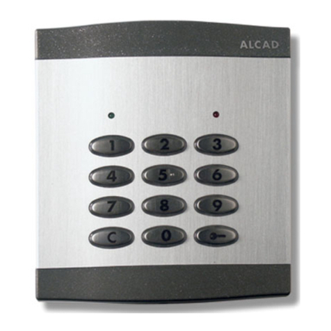
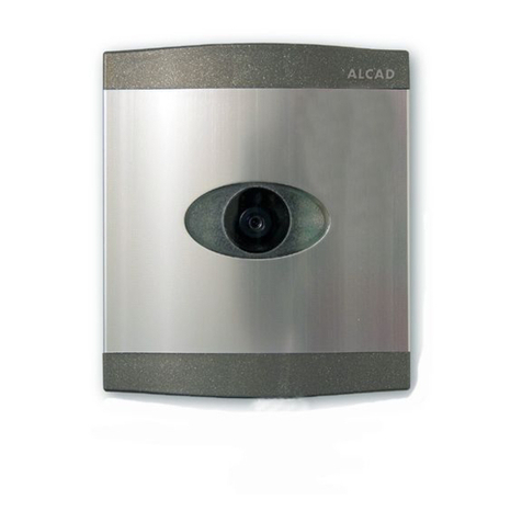
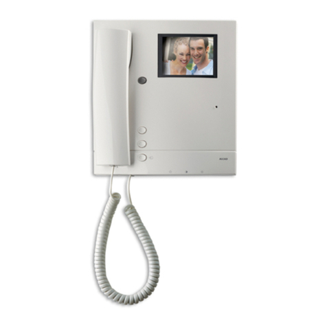
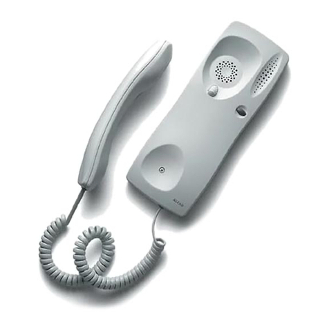
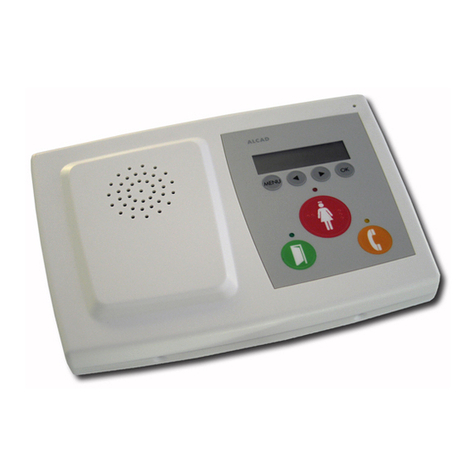
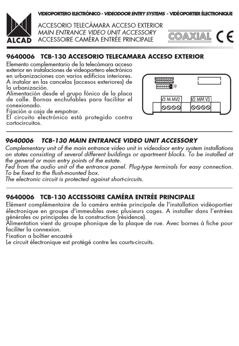
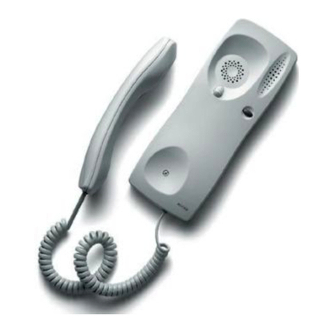
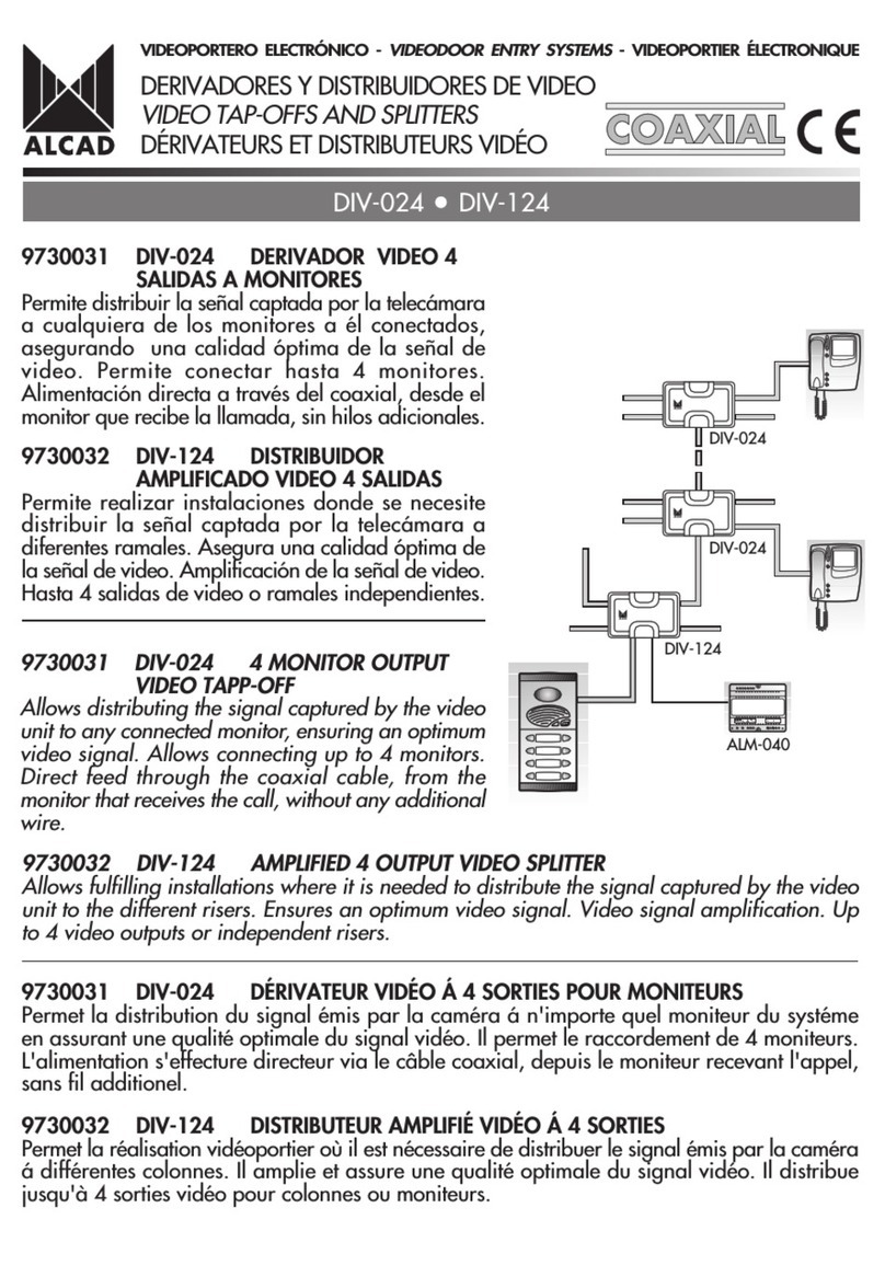
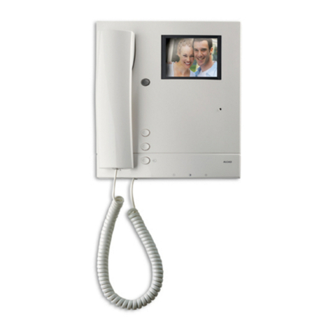
Alcad GRF-200 User manual

GRF-200 TCB-011 TCB-021 SCM-030 ALC-041
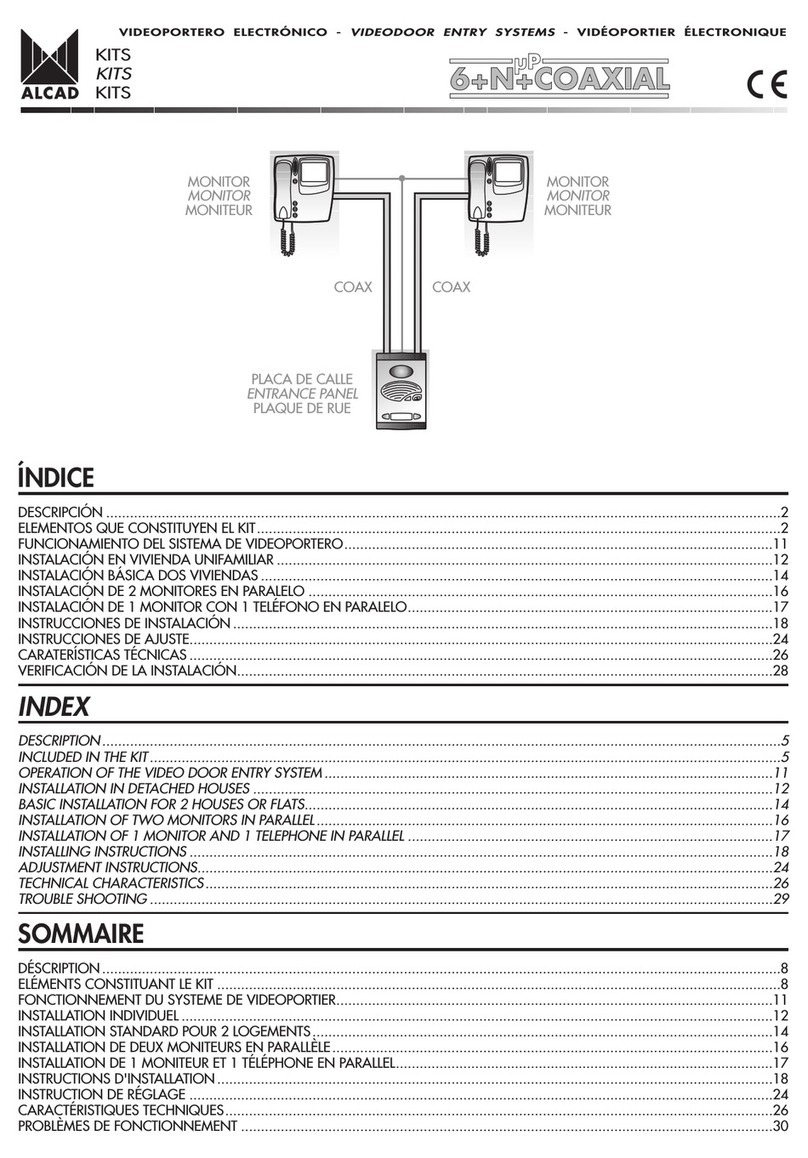
PLACA DE CALLE
ENTRANCE PANEL
PLAQUE DE RUE
ÍNDICE
ELEMENTOS Y DIMENSIONES...................................................................................................................................................2
FUNCIONAMIENTO GENERAL DEL SISTEMA DE VIDEOPORTERO...............................................................................................3
INSTALACIÓN BÁSICA..............................................................................................................................................................5
INSTALACIÓN EN VIVIENDA UNIFAMILIAR CON 2 ACCESOS 2 x KIT 1 VIVIENDA)...................................................................7
INSTALACIÓN DE ELEMENTOS ADICIONALES.........................................................................................................................12
INSTRUCCIONES DE INSTALACIÓN.........................................................................................................................................14
INSTRUCCIONES DE AJUSTE...................................................................................................................................................20
CARACTERÍSTICAS TÉCNICAS.................................................................................................................................................22
VERIFICACIÓN DE LA INSTALACIÓN.......................................................................................................................................24
INDEX
ELEMENTS AND DIMENSIONS..................................................................................................................................................2
GENERAL OPERATION OF THE VIDEO DOOR ENTRY SYSTEM ...................................................................................................3
BASIC INSTALLATION................................................................................................................................................................5
INSTALLATION IN DETACHED HOUSES WITH 2 POINTS OF ENTRY (2 x 1 DWELLING KIT)...........................................................
INSTALLATION OF ADDITIONAL ELEMENTS.............................................................................................................................12
INSTALLING INSTRUCTIONS....................................................................................................................................................14
ADJUSTMENT INSTRUCTIONS.................................................................................................................................................20
TECHNICAL CHARACTERISTICS ...............................................................................................................................................22
TROUBLE SHOOTING .............................................................................................................................................................25
SOMMAIRE
ELÉMENTS ET MESURES ............................................................................................................................................................2
FONCTIONNEMENT GÉNÉRAL DU SYSTÈME DE VIDÉOPORTIER................................................................................................3
INSTALLATION STANDARD........................................................................................................................................................5
INSTALLATION INDIVIDUEL AVEC 2 ACCÉS 2 x KIT 1 LOGEMENT) ............................................................................................7
INSTALLATION DÉLÉMENTS ADDITIONNELS ..........................................................................................................................12
INSTRUCTIONS D'INSTALLATION ............................................................................................................................................14
INSTRUCTION DE RÉGLAGE....................................................................................................................................................20
CARACTÉRISTIQUES TECHNIQUES ..........................................................................................................................................22
PROBLÈMES DE FONCTIONNEMENT.......................................................................................................................................26
MONITOR
MONITOR
MONITEUR
KITS
KITS
KITS
VIDEOPORTERO DIGITAL - DIGITAL VIDEODOOR ENTRY SYSTEMS - VIDÉOPORTIER NUMÉRIQUE

MÓDULOS INTERIORES - INSIDE MODULES - MODULES INTERIEURS
128 mm
195 mm
12 mm
166 mm
193 mm
Abrepuertas
Lock release
Gâche
160 mm
25 mm31 mm
100 mm30 mm
3 mm
1
2
ELEMENTOS Y DIMENSIONES
ELEMENTS AND DIMENSIONS
ELÉMENTS ET MESURES
PLACA DE CALLE - ENTRANCE PANEL - PLAQUE DE RUE
Soporte de conexiones
Connection bracket
Support de connexions
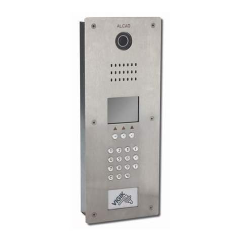
Placa de calle
Entrance panel
Plaque de rue
Caja de empotrar de 3, 4 alturas.
Flush-mounted box of 3, 4 storeys.
Boîtier encastrable de 3, 4 étages.
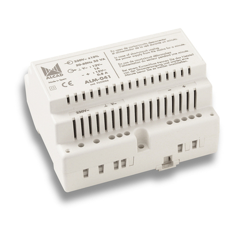
Alimentador
Power supply
Alimentation
9610018
GRF-200
9640002
TC -011
9640009
TC -021
Grupo fónico
Audio unit
Groupe phonique
Telecámara
Video unit
Caméra
KIT
B/N
B/W
N&B
COLOR
COLOR
COULEUR
VIDEOPORTERO DIGITAL - DIGITAL VIDEODOOR ENTRY SYSTEMS - VIDÉOPORTIER NUMÉRIQUE
64.3 mm
197 mm
224 mm
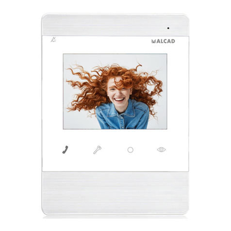
Monitor
Monitor
Moniteur
45 mm
114 mm
179 mm
ARRIBA
UP
HAUT
106 mm
90 mm
60 mm
230 V230 V
1) Los soportes de conexiones incluidos en este kit salen programados de fábrica, almacenando un código asociado a un pulsador
de la placa de calle vea etiqueta identificativa).
(1) The connection brackets included in this kit leave the factory programmed with a code associated to a pushbutton on the entrance
panel (see identifying label).
1) Les supports de connexions inclus dans ce kit sont déjà programmés à lusine, un code associé au bouton poussoir de la plaque
de rue est attribué voir étiquette)
2
1) 1

AUSENCIA DE LLAMADA. SISTEMA EN REPOSO
NO CALL. SYSTEM ON STAND-BY
A SENCE D'APPEL. SYSTÈME EN REPOS
3
La placa de calle se encuentra en reposo, con el sistema de audio deshabilitado. Si levanta el auricular del monitor oirá un tono
continuo. Las funciones de comunicación con placa de calle y apertura de puerta están inhabilitadas . El sistema está a la espera de
que se realice una llamada o de que algún monitor active el sistema de autoencendido vea Cómo activar el sistema de autoencendido).
REALIZAR UNA LLAMADA A UNA VIVIENDA
MAKING A CALL TO A DWELLING
REALISATION D'UN APPEL A UN LOGEMENT
Para llamar a una vivienda, presione el pulsador correspondiente de la placa de calle. La placa emitirá unos tonos de confirmación
de llamada. Si el auricular del monitor está descolgado, la placa emitirá sonidos intermitentes.
Confirmación de llamada
Confirmation of the call
Confirmation de l'appel
TEMPORIZACIONES
TIME-SETTINGS
TEMPORISATION
30 Segundos
Seconds
Secondes
60 Segundos
Seconds
Secondes
To make a call to a dwelling, press the corresponding push-button on the entrance panel with push-buttons. The panel emits a confirmation
tone. If the handset of the monitor called is off the hook, intermittent tones will be heard at the entrance panel.
Pour réaliser un appel à un logement, appuyez sur le bouton-poussoir correspondant de la plaque de boutons-poussoirs de la plaque
de rue. La plaque émettra un signal sonore de validation. Si le moniteur est décroché, la plaque émettra des tonalités intermitentes.
The entrance panel is on stand-by, with the audio system disabled. A continuous tone will be heard if the handset is picked up. The
feature permitting communication with the entrance panel and door-opening are disabled. The system is waiting for a call to be made
or for a monitor to activate the automatic switch-on system. (see Turning on the auto switch-on system).
La plaque de rue est au repos, avec le système du son inactif. En levant le combiné d'un moniteur, on entendra une tonalité continue.
les fonctions de communication avec la plaque de rue et la gâche sont inhibées. Le système attend qu'un appel soit effectué ou qu'un
des moniteurs active le système d'autoallumage. voir Comment activer le système d'auto-allumage).
VIDEOPORTERO DIGITAL - DIGITAL VIDEODOOR ENTRY SYSTEMS - VIDÉOPORTIER NUMÉRIQUE
FUNCIONAMIENTO GENERAL DEL SISTEMA DE VIDEOPORTERO
GENERAL OPERATION OF THE VIDEO DOOR ENTRY SYSTEM
FONCTIONNEMENT GÉNÉRAL DU SYSTÈME DE VIDÉOPORTIER
PIP... PIP... PIP
Tiempo de contestación:
Time to answer:
Temps de réponse:
Tiempo de conversación:
Time for conversation:
Temps de conversation:

4
COMO ACTIVAR EL SISTEMA DE AUTOENCENDIDO
TURNING ON THE AUTO SWITCH-ON SYSTEM
COMMENT ACTIVER LE SYSTÉME D'AUTO-ALLUMAGE
TEMPORIZACIONES
TIME-SETTINGS
TEMPORISATION
30 Segundos
Seconds
Secondes
60 Segundos
Seconds
Secondes
PROLONGACIÓN DEL TIEMPO DE CONVERSACIÓN
EXTENDING THE TIME LIMIT FOR CONVERSATION
PROLONGATION DU TEMPS DE CONVERSATION
Unos segundos antes de finalizar el tiempo de conversación, la placa y el auricular del monitor emitirán una serie de pitidos. Es posible
prolongar el tiempo de conversación desde la placa de calle o desde el monitor indistintamente.
A few seconds before the time allowed for conversation expires, the entrance panel and the receiver on the monitor will emit a series
of beeps. You can extend the conversation time either from the entrance panel or from the monitor.
Quelques secondes avant la fin du temps de conversation, la plaque et lécouteur du moniteur émettra une série de sonneries. Il est
possible de prolonger le temps de conversation à partir de la plaque de rue ou du moniteur.
TEMPORIZACIONES
TIME-SETTINGS
TEMPORISATION
+60 Segundos
Seconds
Secondes
En caso de varios accesos la placa desde donde realiza la llamada quedará activada mientras la otra permanecerá inhabilitada. La
luz roja de esta última parpadeará.
When there are several points of entry, the panel from which the call is being made will remain active while the other will remain
disabled. The red light on the latter will blink.
Dans le cas de plusieurs accès la plaque doù provient lappel sera active pendant que lautre restera inhibée. La lumière rouge de
celle-ci clignotera.
Resto de placas
Others entrance pannels
Autres plaques de rue
Vivienda
Dwelling
Logement
Placa 1
Panel 1
Plaque 1
VIDEOPORTERO DIGITAL - DIGITAL VIDEODOOR ENTRY SYSTEMS - VIDÉOPORTIER NUMÉRIQUE
Tiempo de autoencendido:
Time of automatic switch-on:
Temps dauto-allumage:
Tiempo de conversación:
Time for conversation:
Temps de conversation:
Tiempo de conversación:
Time for conversation:
Temps de conversation:
Pulsar y soltar
Press and release
Appuyez un instant

1) Máx. 15 Vdc, 0,5 A
2
22
22
2
230 V 230 V
Funcionamiento - Opera ion - Fonctionnement
5
ESQUEMA UNIFILAR - SINGLE-WIRED DIAGRAM - SCHÉMA À UN FIL
2
2
2
SCM-030
MVB-002
MVC-002
ALC-041
230 V )
INSTALACIÓN ÁSICA
BASIC INSTALLATION
INSTALLATION STANDARD
1 mm 2
TABLA DE SECCIONES
AWG
1,1 mm 17
COAXIAL 75 W
SECTION TABLE
TABLEAU DE SECTIONS
0,8 mm 20
0,5 mm 2
1 mm 2
1,1 mm 17
Hasta 100 m - Up to 100 m - Jusqu'à 100 m
Hasta 25 m - Up to 25 m - Jusqu'à 25 m 2
SCM-030
MVB-002
MVC-002
22
SCM-030
MVB-002
MVC-002
ABR-015
1)
ALC-041
230 V )
ABR-015
1)
COAX
COAX
KIT 1 VIVIENDA
1 DWELLING KIT
KIT 1 LOGEMENT
KIT 2 VIVIENDAS
2 DWELLINGS KIT
KIT 2 LOGEMENTS
VIDEOPORTERO DIGITAL - DIGITAL VIDEODOOR ENTRY SYSTEMS - VIDÉOPORTIER NUMÉRIQUE
RECEPCIÓN DE LLAMADAS. SISTEMA ACTIVADO.
El monitor asociado al pulsador recibe la llamada emitiendo un aviso sonoro y encendiendose la pantalla. Dispone de un tiempo para
contestar. Pasado este tiempo, el sistema vuelve al estado de reposo. Al descolgar el auricular del monitor, se establecerá la comunicación
con la placa de calle, empezando el tiempo de conversación. Durante este tiempo podrá abrir la puerta desde el monitor escuchándose,
si está habilitado, un tono de apertura de puerta puente J2 colocado). Posibilidad de prolongar el tiempo de conversación consulte
página 4). Si es el caso y levanta el auricular del monitor de la otra vivienda, oirá tonos intermitentes.
Finalizado el tiempo de conversación o una vez colgado el auricular, el sistema vuelve al estado de reposo.
Nota: podrá consultar las temporizaciones del sistema en la página 3.
1
2
MAKING A CALL. SYSTEM ACTIVATED.
The monitor associated to the pushbutton receives the call, emitting an alert signal and turning on the screen. You are allowed a certain
period of time to answer. Once this period has expired, the system reverts to being on standby. When the receiver of the monitor is
picked up, communication will be established with the entrance panel, thereby starting the time allowed for communication. During
this period of time, you can open the door from the monitor. If this feature is enabled, you will be able to hear the door-opening tone
(J2 jumper in place). You can also extend the conversation time (see page 4). In this case, and if the receiver of the other dwelling is
picked up, you will hear beeping tones. When the time allowed for conversation expires, or when the user hangs up the receiver, the
system reverts to being on standby.
Note: You will find the time-settings of the system on page 3.
RÉCEPTION D'APPELS. SYSTÈME ACTIVÉ.
Le moniteur associé au bouton poussoir reçoit lappel à travers des sonneries et lallumage de lécran. Vous disposez dun temps
pour répondre. Une fois le temps écoulé, le système est au repos. En décrochant le combiné du moniteur, la communication avec la
plaque de rue sera établie ainsi que le temps de conversation. Pendant ce temps, vous pourrez ouvrir la porte à partir du moniteur,
vous entendrez une tonalité de gâche lors de son habilitation cavalier J2 installé). Possibilité de prolonger le temps de conversation
voir page 4). Si cest le cas, vous décrochez le combiné du moniteur de lautre logement, vous entendrez des sonneries discontinues.
Une fois le temps de conversation ou bien un fois raccroché le combiné, le système sera au repos.
Note: vous pourrez consulter les temporisations du système à la page 3.

19
19
J1
GRF-200
cod. 9610018
J2
TCB-011
TCB-021
GRF-200
R1
CC1
J1J1
A
V1
V1
25
26
27
24
M
S5
M
S2 D1 D2
R1
CC1
J1J1
A
V1
V1
25
26
27
24
M
S5
M
S2 D1 D2
910 1222
SC1
7
D1D2 D3
11
+
6
230 V
230 V
+_
ALC-041
Extraer la resistencia de las bornas
V2,M) donde vaya a conectar el cable
coaxial pasos 1 y 2).
Extract the resistence from the terminals
(V2, M) where the coaxial cable is to
be connected (steps 1 and 2)
Ôter la résistance des bornes V2, M)
ou le câble coaxial va être connectée
point 1 et 2).
INSTALACIÓN ÁSICA - BASIC INSTALLATION - INSTALLATION STANDARD
KIT 2 VIVIENDAS
2 DWELLINGS KIT
KIT 2 LOGEMENTS
VIDEOPORTERO DIGITAL - DIGITAL VIDEODOOR ENTRY SYSTEMS - VIDÉOPORTIER NUMÉRIQUE
ABR-015
Rojo
Red
Rouge
Blanco
White
Blanc
75 Ohm
V2 M MV2 V1 M MV4
J1
81234567
R1
AJ1
SCM-030
75 Ohm
19 +_
V2 M MV2
R1
AJ1
12

1) Máx. 15 Vdc, 0,5 A
22
2
230 V 230 V
Funcionamiento - Opera ion - Fonctionnement
RECEPCIÓN DE LLAMADAS. SISTEMA ACTIVADO.
Ambos monitores reciben la llamada simultáneamente emitiendo un aviso sonoro y encendiendose la pantalla. Dispone de un tiempo
para contestar. Pasado este tiempo, el sistema vuelve al estado de reposo. Al descolgar el auricular de uno de los monitores, se
establecerá la comunicación con la placa de calle, empezando el tiempo de conversación. Durante este tiempo podrá abrir la puerta
desde el monitor escuchándose, si está habilitado, un tono de apertura de puerta puente J2 colocado). Posibilidad de prolongar el
tiempo de conversación consulte página 4). Si levanta el auricular del otro monitor, oirá tonos intermitentes.
Finalizado el tiempo de conversación o una vez colgado el auricular, el sistema vuelve al estado de reposo.
Nota: podrá consultar las temporizaciones del sistema en la página 3.
MAKING A CALL. SYSTEM ACTIVATED.
Both monitors receive the call simultaneously, emitting an alert signal and turning on the screen. You are allowed a certain period of
time to answer. Once this period has expired, the system reverts to being on standby. When the receiver of one of the monitors is
picked up, communication will be established with the entrance panel, thereby starting the time allowed for communication. During
this period of time, you can open the door from the monitor. If this feature is enabled, you will be able to hear the door-opening tone
(J2 jumper in place). You can also extend the conversation time (see page 4). If you pick up the receiver of the other monitor, you will
hear beeping tones. When the time allowed for conversation expires, or when the user hangs up the receiver, the system reverts to
being on standby.
No e: You will find the time-settings of the system on page 3.
7
ESQUEMA UNIFILAR - SINGLE-WIRED DIAGRAM - SCHÉMA À UN FIL
2
2
2
ABR-015
1)
MVB-002
MVC-002
1 mm 2
TABLA DE SECCIONES
AWG
1,1 mm 17
COAXIAL 75 W
SECTION TABLE
TABLEAU DE SECTIONS
0,8 mm 20
0,5 mm 2
1 mm 2
1,1 mm 17
Hasta 100 m - Up to 100 m - Jusqu'à 100 m
Hasta 25 m - Up to 25 m - Jusqu'à 25 m
INSTALACIÓN EN VIVIENDA UNIFAMILIAR CON 2 ACCESOS (2 x KIT 1 VIVIENDA)
INSTALLATION IN DETACHED HOUSES WITH 2 POINTS OF ENTRY (2 x 1 DWELLING KIT)
INSTALLATION INDIVIDUEL AVEC 2 ACCÉS (2 x KIT 1 LOGEMENT)
ABR-015
1)
ALC-041
230 V )
2
2
MVB-002
MVC-002
SCM-030SCM-030
ALC-041
230 V )
Placa de calle principal
Main entrance panel
Plaque de rue principale
Placa de calle secundaria
Secondary entrance panel
Plaque de rue secondaire
2
COAX
COAX
KIT 1 VIVIENDA
1 DWELLING KIT
KIT 1 LOGEMENT
KIT 1 VIVIENDA
1 DWELLING KIT
KIT 1 LOGEMENT
VIDEOPORTERO DIGITAL - DIGITAL VIDEODOOR ENTRY SYSTEMS - VIDÉOPORTIER NUMÉRIQUE
RÉCEPTION D'APPELS. SYSTÈME ACTIVÉ.
Les deux moniteurs reçoivent lappel simultanément en émettant un signal sonore et en allumant lécran. Vous disposez dun temps
pour répondre. Une fois le temps écoulé, le système est au repos. En décrochant le combiné du moniteur, la communication avec la
plaque de rue sera établie ainsi que le temps de conversation. Pendant ce temps, vous pourrez ouvrir la porte à partir du moniteur,
vous entendrez une tonalité de gâche lors de son habilitation. cavalier J2 installé). Possibilité de prolonger le temps de conversation
voir page 4). Si cest le cas, vous décrochez le combiné du moniteur de lautre logement, vous entendrez des sonneries discontinues.
Une fois le temps de conversation ou bien un fois raccroché le combiné, le système sera au repos.
Note: vous pourrez consulter les temporisations du système à la page 3.

19
19
J1
GRF-200
cod. 9610018
J2
TCB-011
TCB-021
GRF-200
R1
CC1
J1J1
A
V1
V1
25
26
27
24
M
S5
M
S2 D1 D2
910 1222
SC1
7
D1D2 D3
11
+
R1
CC1
J1J1
A
V1
V1
25
26
27
24
M
S5
M
S2 D1 D2
8
J1: Sólo debe haber una placa principal por instalación placa con puente J1 colocado)
J1: Il ny en a quune plaque de rue principale par installation plaque avec le cavalier J1 monté)
J1: An installation must have only one main entrance panel (panel with the jumper J1 installed)
230 V
230 V
+_
ALC-041
Extraer la resistencia de las bornas V2,M) donde
vaya a conectar el cable coaxial pasos 1 y 2).
Extract the resistence from the terminals (V2, M)
where the coaxial cable is to be connected (steps
1 and 2)
Ôter la résistance des bornes V2, M) ou le câble
coaxial va être connectée point 1 et 2).
INSTALACIÓN EN VIVIENDA UNIFAMILIAR CON 2 ACCESOS (2 x KIT 1 VIVIENDA) - INSTALLATION IN DETACHED HOUSES
WITH 2 POINTS OF ENTRY (2 x 1 DWELLING KIT) - INSTALLATION INDIVIDUEL AVEC 2 ACCÉS (2 x KIT 1 LOGEMENT)
VIDEOPORTERO DIGITAL - DIGITAL VIDEODOOR ENTRY SYSTEMS - VIDÉOPORTIER NUMÉRIQUE
ABR-015
Rojo
Red
Rouge
Blanco
White
Blanc
V2 M MV2
1) Placa de calle principal Deje el puente J1 colocado)
Main entrance panel (Leave the J1 jumper in place)
Plaque de rue principale laisez le cavalier J1 installé)
81234567
Rojo
Red
Rouge
Blanco
White
Blanc
19
+
19
V1
R1
AJ1
V1
R1
AJ1
75 Ohm
1)
J1
SCM-030
75 Ohm
V1 M MV4

19
19
J1
GRF-200
cod. 9610018
J2
TCB-011
TCB-021
GRF-200
910 1222
SC1
7
D1D2 D3
11
+
9
230 V
230 V
+_
ALC-041
Extraer la resistencia de las bornas V2,M) donde
vaya a conectar el cable coaxial pasos 1 y 2).
Extract the resistence from the terminals (V2, M)
where the coaxial cable is to be connected (steps
1 and 2)
Ôter la résistance des bornes V2, M) ou le câble
coaxial va être connectée point 1 et 2).
Nota: Deberá volver a programar uno de los dos soportes de conexiones, consulte página 10.
Note: Il faut reprogrammer un des supports de conexions, voir page 10.
No e: You will have to re-program one of the brackets, see page 10.
VIDEOPORTERO DIGITAL - DIGITAL VIDEODOOR ENTRY SYSTEMS - VIDÉOPORTIER NUMÉRIQUE
ABR-015
Rojo
Red
Rouge
Blanco
White
Blanc
75 Ohm
V2 M MV2 V1 M MV4
81234567
Rojo
Red
Rouge
Blanco
White
Blanc
19
+
19
2)
J1
2) Placa de calle secundaria retire el puente J1)
Secondary entrance panel (Remove the J1 jumper)
Plaque de rue secondaire Enlever le cavalier J1)
75 Ohm

10
PASOS PROGRAMACIÓN - PROGRAMMING STEPS - ETAPES DE PROGRAMMATION
1Desplace el interruptor PROG a la posición OFF 1.1); el tono desaparacerá. Vuelva a poner el interruptor en la posición ON 1.2).
2Pulse el botón de abrepuertas. Se activará el audio y el video entre el monitor y la placa de calle principal. El monitor estará
preparado para recibir un código.
3Situado en la placa de calle principal, presione el pulsador de la placa de calle correspondiente a la vivienda. La placa emitirá
un sonido de confirmación. El soporte está programado.
4Compruebe el funcionamiento del monitor verificación de llamada, audio y abrepuertas). Si el monitor no funciona correctamente
vuelva al paso 1.
Nota : Tiempo máximo de 1 minuto entre los pasos 1 y 2 y entre 2 y 3. El sistema avisa mediante pitidos del fin del tiempo máximo
entre 2 y 3; repita el paso 2 para tener otro minuto. Pasado el tiempo máximo deberá iniciar la programación desde el paso 1.
1Turn the PROG switch to the OFF position (1.1), the tone stops. Turn the switch back to the ON position (1.2).
2Press the lock release button. The audio and the video will be activated between the monitor and the main panel. The monitor is
ready to receive the code.
3From the main entrance panel, make the call to the house or flat when monitor to be programmed is installed. The panel emits a
confirmation tone. The connection bracket has been programed.
4Check the operation of the monitor (call, audio and door opening). If the monitor does not function correctly then repeat the process
from Step 1.
No e: Maximum time limit of 1 minute between Steps 1 and 2 and between 2 and 3. The system warns by means of a series of beeps
of the end of the time limit between Steps 2 and 3; repeat Step 2 to have another minute. If the time limit is exceeded the process must
be repeated from Step 1.
1Mettez linterrupteur PROG sur OFF 1.1); la sonnerie disparaîtra. Repositionnez linterrupteur sur ON 1.2)
2Appuyer sur le bouton douverture de porte. L'audio et le vidéo seront activées entre la plaque principale et le moniteur. Le support
de connexions est préparé pour recevoir le code.
3Situé sur la plaque de rue principale, réalise l'appel à l'appartement, là où le moniteur à programmer est installé. La plaque émettra
un signal sonore de validation. Le support de connexions est programé.
4Vérifier le fonctionnement du moniteur appel, audio et ouvertures des portes). Si le moniteur ne fonctionne pas correctement
retournez au point 1.
Note: Temps maximal 1 minute entre les points 1 et 2 et entre 2 et 3. Le système prévient par une série de signaux sonores la fin du
temps maximal entre les points 2 et 3; répétez le point 2 pour obtenir une minute en plus. Si vous excèdez le temps maximal il faudra
de nouveau programmer à partir du point 1.
INSTALACIÓN EN VIVIENDA UNIFAMILIAR CON 2 ACCESOS
INSTALLATION IN DETACHED HOUSES WITH 2 POINTS OF ENTRY
INSTALLATION INDIVIDUEL AVEC 2 ACCÉS
VIDEOPORTERO DIGITAL - DIGITAL VIDEODOOR ENTRY SYSTEMS - VIDÉOPORTIER NUMÉRIQUE
INSTRUCCIONES DE PROGRAMACIÓN
PROGRAMMING INSTRUCTIONS
INSTRUCTIONS DE PROGRAMMATION
La programación del soporte de conexiones debe realizarse desde la placa de calle del sistema que este configurada como principal
puente J1 del grupo fónico colocado, vea esquema página 8).
Para programar el soporte de conexiones deberá estar preparado para recibir el código. Para ello conecte un monitor al soporte de
conexiones a través del latiguillo y monte el auricular al monitor consulte pasos 1 y 4 de la página 18) y siga los pasos que se indican
a continuación:
To program the connections bracket, it must first be made ready to receive the code. To do this, connect a monitor to the connections
bracket using the connecting strip, mount a receiver on the monitor (see steps 1 and 4 on page 18), and follow these steps:
Pour programmer le support de connexions, il faudra être préparé pour recevoir le code. Pour cela connecter le moniteur au support
de connexions à travers les pontets et installer le combiné sur le moniteur voir points 1 et 4, page 18), suivez les indications suivantes:
The programming of the connections bracket must be carried out from the entrance panel which is configured as the main panel of
the system (with J1 jumper in place: see wiring diagram on page 8).
La programmation du support de connexions doit se réaliser de la plaque de rue du système que celui-ci configure comme principal
pont J1 positionné, voir schéma du câblage, page 8).
PASOS PROGRAMACIÓN - PROGRAMMING STEPS - ETAPES DE PROGRAMMATION
9
60
6
12
18
24
60
36
42
48
54 01
2
3
4
5
6
7
8
9
60
6
12
18
24
60
36
42
48
54 01
2
3
4
5
6
7
8
Soporte programado
Bracket programmed
Support programme
11
Tiempo máximo
Maximum time limit
Temps maximal
Tiempo máximo
Maximum time limit
Temps maximal
VIDEOPORTERO DIGITAL - DIGITAL VIDEODOOR ENTRY SYSTEMS - VIDÉOPORTIER NUMÉRIQUE
PROG
OFF
PROG
ON
1.1
1.2

APERTURA DE PUERTA DESDE EL INTERIOR
DOOR OPENING FROM INSIDE
OUVERTURE DE PORTE DEPUIS L'INTÉRIEUR
19
J1
GRF-200
cod. 9610018
J2
910 12
SC1
7
D1D2 D3
+22 11
81234567
Pulsador
Push-button
Boutton-poussoir
GRF-200
12
INSTALACIÓN DE ELEMENTOS ADICIONALES
INSTALLATION OF ADDITIONAL ELEMENTS
INSTALLATION DÉLÉMENTS ADDITIONNELS
Las bornas 24, 25 y 26, 27 son contactos libres de potencial. A la hora de utilizarlas tenga en cuenta las siguientes limitaciones de
conexión: 50 mA@12 Vdc.
Terminals number 24, 25 and 26, 2 are potential-free contacts. To use them, take into account the following connection limitations:
50 mA@12 Vdc.
Les bornes 24, 25 et 26, 27 sont des contactes libre de potentiel. Pour les employer, tenez compte des limitations de connexion suivants:
50 mA@12 Vdc.
VIDEOPORTERO DIGITAL - DIGITAL VIDEODOOR ENTRY SYSTEMS - VIDÉOPORTIER NUMÉRIQUE
CONEXIÓN PULSADORES AUXILIARES MONITOR
CONNECTION OF THE MONITOR'S AUXILIARY PUSH-BUTTONS
CONNEXION DES OUTONS AUXILIAIRES DU MONITEUR
22
2
2
2
ALC-041
230 V )
ABR-015 Pulsador
Push-button
Boutton-poussoir
230 V
PULSADOR AUXILIAR 2
AUXILIARY PUSH-BUTTON 2
OUTON AUXILIAIRE 2
Activación
Ac iva ion
Activation
Conexión
Connec ion
Connexion
Accesorio
Accessory
Accesoire
SCM-030
D1 D2
25
26
27
S5
24
S2
PULSADOR AUXILIAR 1
AUXILIARY PUSH-BUTTON 1
OUTON AUXILIAIRE 1
Activación
Ac iva ion
Activation
Conexión
Connec ion
Connexion
Accesorio
Accessory
Accesoire
SCM-030
D1 D2
25
26
27
S5
24
S2

CONEXIÓN DE A REPUERTAS AC
CONNECTING AN AC ELECTRIC LOCK
CONNEXIONS DES GÂCHES AC
19
J1
GRF-200
cod. 9610018
J2
230 V
910 12 22
SC1
7
D1D2 D3
11
+
81234567
230 V
V
~
1)
ALA-020
ABR-001
Retire la conexión entre las bornas 10 y
Remove the jumper between terminal 10 and
Ôter le branchement entre la borne 10 et
2) Tono apertura de puerta habilitado
Door-opening tone enabled
Tonalité de gâche: on
3) Tono apertura de puerta deshabilitado
Door-opening tone disabled
Tonalité de gâche: off
GRF-200
910 12 22
SC1
11
+
3)
J2
2)
J2
1) Utilice manguera independiente.
Use separate cable hose.
Utiliser une gaine indépendante.
13
VIDEOPORTERO DIGITAL - DIGITAL VIDEODOOR ENTRY SYSTEMS - VIDÉOPORTIER NUMÉRIQUE
2
2
2
2
ALC-041
230 V )
ABR-001
ALA-020
230 V )
2
1) Utilice manguera independiente.
Use separate cable hose.
Utiliser une gaine indépendante.
1)
230 V V
230 V

14
INSTRUCCIONES DE INSTALACIÓN
INSTALLING INSTRUCTIONS
INSTRUCTIONS D'INSTALLATION
RECOMENDACIONES - RECOMMENDATIONS - RECOMMANDATIONS
A la hora de colocar la placa de calle, asegúrese que ni los rayos del sol ni fuentes de luz intensa incidan directamente sobre la
telecámara, evitando así efectos no deseados en la visualización de la imagen efecto contraluz) y manteniendo la vida útil del equipo.
When installing the entrance panel make sure that the sunrays or intense light sources do not fall directly on the video unit, avoiding
nonwhished effects in picture display (backlight effect) and same way keeping the operational life of the equipment.
Lorsque vous installerez la plaque de rue, assurez-vous bien que les rayons solaires ou une autre source de lumière intense ne coïncide
pas directement sur la caméra, vous evíterez ainsi les problémes de visualisation effet contre jour,...) et préserverait la vie du matériel.
CAJA DE EMPOTRAR - FLUSH MOUNTED BOX - OÎTIER ENCASTRA LE
Rompa el tabique de las aberturas que requiera
para pasar los cables.
Break off the perforated holes that you need to
pass the cables through.
Cassez la cloison des ouvertures nécessaires pour
faire passer les câbles.
1Coloque la caja de empotrar de modo que la
parte superior quede a una altura de 1,7 m.
Place the flush-mounted box in position so that
the top is 1. m. high.
Placez le boîtier encastrable de telle sorte que la
partie supérieure soit placée à une hauteur de
1,7 m.
2
1,7 m
Levante, haciendo palanca, la pestaña del tarjetero
y coloque la etiqueta identificadora de cada
pulsador.
Lever open the cover of the card-holder and insert
the card that identifies the pushbutton
Levez la languette du panneau d'étiquettes en
faisant levier, et placez l'étiquette d'identification
correspondant à chaque bouton-poussoir.
1
PLACA DE CALLE - ENTRANCE PANEL - PLAQUE DE RUE
VIDEOPORTERO DIGITAL - DIGITAL VIDEODOOR ENTRY SYSTEMS - VIDÉOPORTIER NUMÉRIQUE

Realice las conexiones eléctricas. Consulte los
esquemas de cableado.
4
Make the electrical connections. See wired
diagrams.
Réalisez les connexions électriques. Voir schémas
de cablage.
Place the rings of the panel over the extracted
fixing pins. The unused pins should be placed in
their slots.
Introduzca las anillas de la placa sobre los
bisagras. Introduzca completamente en sus ranuras
las bisagras no utilizadas.
Introduisez les anneaux de la plaque sur les axes
de fixation retirés. Introduisez complètement dans
leurs rainures les axes non utilisés.
3
Extraiga los tapones y las bisagras de la caja de
empotrar. Extraiga las dos bisagras que requiera
según quiera abrir la placa hacia la derecha, la
izquierda o hacia abajo.
Remove the caps and the fixing pins from the
flush-mounted box. Choose the two fixing pins
you want to hinge the panel on to, so that it opens
either to the right or to the left or downwards.
Retirez les bouchons et les axes de fixation du
boîtier encastrable. Enlevez les deux axes requis
suivant si vous voulez ouvrir la plaque vers la
droite, vers la gauche ou bien vers le bas.
2
15
Realizada la conexión del resto de componentes
de la instalación y montado el monitor en el
soporte de conexiones, podrá realizar una
llamada. Realice entonces el ajuste de la placa
de calle. Consulte página 21.
5
Once the connection of the other components of
the installation have been made and the monitor
mounted on the connections bracket, you will be
able to make calls. Now adjust the entrance panel.
See page 21.
Réaliser la connexion et réglage du reste des
composants de linstallation et installer le moniteur
sur le support de connexions, vous pourrez réaliser
un appel. Fait alors le réglage de la plaque de
rue. Voir page 21.
VIDEOPORTERO DIGITAL - DIGITAL VIDEODOOR ENTRY SYSTEMS - VIDÉOPORTIER NUMÉRIQUE

ALIMENTADOR - POWER SUPPLY - ALIMENTATION
Montaje en carril DIN.
Mounting on a DIN rail.
Montage sur rail DIN.
2
Coloque el alimentador en un lugar bien ventilado, sin humedad y alejado de fuentes directas de calor. Evite obstruir las ranuras de
ventilación y proteja el alimentador, cumpliendo con la normativa vigente en materia de instalaciones eléctricas magnetotérmicos,
diferenciales...).
Install the power supply unit in a dry, well-ventilated place away from direct sources of heat. Avoid blocking the ventilation slots. Protect
the power supply unit by complying with existing regulations governing electrical installations (avoid high-temperature locations and
strong magnetic fields, ensure correct fusing, etc.).
Installer lalimentation dans un endroit bien aéré, sans humidité et éloigné de sources directes de chaleur. Eviter lobstruction des ouies
de ventilation et protéger lalimentation, en accord avec la norme en matière dinstallation électrique magnétothermiques, différentiels...)
For mounting it on a wall, fix the power supply
with plugs and screws that have been supplied.
Pour le montage sur le mur, fixez l'alimentation
à l'aide des chevilles et vis fournies.
1Para montaje a pared, fije el alimentador con los
tacos y tornillos suministrados.
Si necesita desmontar el alimentador de un carril
DIN, desplace ligeramente la pestaña de sujeción
hacia abajo 1). Separe la parte inferior del
alimentador del carril DIN 2).
3
If you need to dismount the power supply unit
from a DIN rail, lightly press the fixing tab
downwards (1). Separate the lower part of the
power supply unit from the DIN rain (2).
Si vous avez besoin de démonter l'alimentation
du rail DIN, déplacer légèrement le clips de fixation
vers le bas 1) Séparer la partie inférieure de
l'alimentation du rail DIN 2).
16
Realice las conexiones del alimentador con los
elementos que conforman el portero según se
indica en los esquemas de cableado.
Connect up the power supply with the elements
that make up the door entry system as shown in
the wired diagrams.
Branchez l'alimentation avec les éléments qui
composent le système du portier comme illustré
dans les schémas de cablage.
4
VIDEOPORTERO DIGITAL - DIGITAL VIDEODOOR ENTRY SYSTEMS - VIDÉOPORTIER NUMÉRIQUE

1,6 m
17
SOPORTE DE CONEXIONES - CONNECTION BRACKET - SUPPORT DE CONNEXIONS
RECOMENDACIONES - RECOMMENDATIONS - RECOMMANDATIONS
A la hora de elegir el lugar para colocar el soporte, busque una zona de pared plana, uniforme y dura. En caso de fijar el soporte a
una caja de mecanismos universal, asegúrese de que ésta queda uniformemente alineada con la pared. De esta manera, conseguirá
una óptima sujeción del monitor.
Colóquelo alejado de fuentes de luz directa, evitando así efectos no deseados en la visualización de la imagen reflejos,...). Evite también
fuentes intensas de calor, humedad, vapor, que podrían limitar la vida útil del equipo.
Choose an area of smooth, uniform and hard wall when deciding where to place the monitor. If the bracket is fixed to a standard electrical
box, make sure that this is uniformly aligned. This way you will get an optimal fixing of the monitor.
Put it far from direct light sources, avoiding nonwhished effects in picture display (reflections,...). Same way avoid hard sources of heat,
humidity, steam, that could reduce the operational life of the equipment.
Choisissez une paroi uniforme, dure et plane pour linstallation du moniteur. Dans le cas où vous fixez le support à un boîtier d'appareillage
universel, assurez-vous quil reste bien aligné sur la paroi. De cette façon, vous obtiendrez une fixation optimale du moniteur.
Eloignez les sources de lumière directe, vous evíterez ainsi les problémes de visualisation reflets,...). Evitez les sources importantes de
chaleur, humidité, vapeur d'eau qui sont susceptible de réduire la vie du matériel.
Fije el soporte de conexiones a la pared con los
tacos y tirafondos suministrados. Se recomienda
utilizar los anclajes de los 4 extremos. Colóquelo
de modo que la parte superior quede a una altura
de 1,6 m.
Fix the connection bracket to the wall with plugs
and screws supplied. 4 holes placed on the corners
are recommended. Put in a way that the upper
part is at a height of 1.6 metres.
Fixer le support des connexions au mur à laide
des chevilles et vis fournies. Il est recommandé
d'utiliser les ancrages par les 4 extrémités. Installez-
le de façon à que la partie supérieure reste a une
hauteur de 1,6 m.
1Tambien puede fijar el soporte a una caja de
mecanismos universal de 60 mm.
2
Bracket can also be fixed to a standard 60 mm
electrical box.
Vous pouvez aussi fixer le support a un boîtier
d'appareillage universel de 60 mm.
Corte las aberturas pretroqueladas que necesite
del cubrebornas. Fíjelo al alimentador utilizando
los tornillos de sujeción.
Cassez les trous prédécoupés requis pour le couvre-
borne. Fixez le couvre-borne sur l'alimentation
en utilisant les vis de fixation fournies.
Cut the required perforated openings of the
terminal cover. Fix it to the power supply unit
using the fixing screws.
5
VIDEOPORTERO DIGITAL - DIGITAL VIDEODOOR ENTRY SYSTEMS - VIDÉOPORTIER NUMÉRIQUE
1,5 m

1
1
3
4
2
18
Realice las conexiones eléctricas. Consulte los
esquemas de cableado. Verifique el ajuste.
Consulte página 20.
3
Make the electrical connections. Consult wired
diagrams. Check the adjustment. Consult Page
20.
Réalisez les connexions électriques. Voir schémas
de cablage. Vérifier le réglage. Voir page 20.
MONITOR - MONITEUR - MONITOR
Conecte el latiguillo del monitor en el soporte de
conexiones.
1
Connect the monitor connector to the connection
bracket.
Connectez le câble du moniteur sur le support de
connexion.
Conecte el cordón entre la base del monitor y el
auricular.
4
Connect the cord between the base of the monitor
and the receiver.
Connectez le fil entre la base du moniteur et le
combiné.
2Encaje las dos pestañas superiores de sujeción
en las guias de la base del monitor 1). Para ello,
incline el monitor como se muestra en la figura.
Insert the top two fitting hooks on the bracket into
the guide slots on the back of the monitor housing
(1). To do so, incline the monitor as shown in the
picture below.
Engagéz les deux ergots supérieurs dans
l'emplacement préur sur la base du moniteur 1).
Pour cela, inclinez le moniteur comme indiqué sur
la figure.
3Empuje hacia abajo el monitor 2). Manteniendo
dicho empuje 2), presione frontalmente la parte
inferior del monitor 3) hasta colocar el monitor
paralelo a la pared. Desplace ligeramente el
monitor hacia arriba para anclarlo al soporte de
conexiones 4).
Push the monitor downwards (2). While still
pushing (2), apply frontal pressure to the lower
part of the monitor (3) until it is in a position
parallel to the wall. Then move the monitor slightly
upwards to anchor it to the connections support
(4).
Appuyer vers la partie basse du moniteur 2).
Maintenir appuyer 2), Presser frontalement la
partie inférieure du moniteur 3) jusqu'à placer
le moniteur parallèlement au mur. Déplacer
légèrement le moniteur vers le haut pour
lenclencher dans le support de connexions.
VIDEOPORTERO DIGITAL - DIGITAL VIDEODOOR ENTRY SYSTEMS - VIDÉOPORTIER NUMÉRIQUE

19
COMO DESMONTAR EL MONITOR DEL SOPORTE DE CONEXIONES
HOW TO DISMOUNT THE MONITOR FROM THE CONNECTION BRACKET
COMMENT DÉMONTER LE MONITEUR DU SUPPORT DE CONNEXIONS
3Desplace el monitor hacia arriba.
Slide up the monitor.
Déplacer le moniteur vers le haut.
Desplace ligeramente la pestaña de sujeción hacia
abajo 1). Empuje hacia abajo el monitor 2).
1
Pull slightly on the flange downwards(1). Push the
monitor downwards (2).
Déplacez légérement l'ergot ver le bas 1). Appuyez
vers le bas le moniteur 2).
Separe la parte inferior del monitor del soporte
de conexiones 3).
2
Separate the lower part of the monitor from the
connection bracket (3).
Séparez la partie inférieure du moniteur du support
de connexion 3).
VIDEOPORTERO DIGITAL - DIGITAL VIDEODOOR ENTRY SYSTEMS - VIDÉOPORTIER NUMÉRIQUE

20
SOPORTE DE CONEXIONES - CONNECTION BRACKET - SUPPORT DE CONNEXIONS
2Coloque del puente J1 en función de la instalación.
Jumper J1 configuration according to the
instalation.
Configuration du cavalier J1 selon l'installation.
INSTRUCCIONES DE AJUSTE
ADJUSTMENT INSTRUCTIONS
INSTRUCTIONS DE RÉGLAGE
A
A
B
B
1En caso necesario ajuste el volumen de llamada.
Nota: Para comprobar el volumen de llamada
del monitor deberá tener este conectado al soporte
de conexiones y realizar una llamada desde la
placa de calle.
If necessary, adjust the call volume level.
No a: To test the call volume of the monitor, the
latter must be connected to the connections bracket
and a call made from the entrance panel.
Régler le volume de l'appel si vous en avez besoin.
Note: Pour verifier le volume sonore de l'appel
du moniteur, il faudra le connecter au support de
connexions et réaliser un appel depuis la plaque
de rue.
TIPO DE INSTALACIÓN
TYPE OF INSTALLATION
TYPE D'INSTALLATION
POSICIÓN PUENTE J1
J1 JUMPER POSITION
POSITION CAVALIER J1
VIDEOPORTERO DIGITAL - DIGITAL VIDEODOOR ENTRY SYSTEMS - VIDÉOPORTIER NUMÉRIQUE
DIV-024
DIV-124
Alimentación
Power supply
Alimentation
2
R1
J1
R1
AJ1
Other manuals for GRF-200
1
This manual suits for next models
7
Table of contents
Other Alcad Intercom System manuals

Alcad
Alcad CHC-041 User manual

Alcad
Alcad ENARA User manual

Alcad
Alcad 968 Series User manual

Alcad
Alcad 967 Series User manual

Alcad
Alcad 972 Series User manual

Alcad
Alcad TCB-010 User manual

Alcad
Alcad CHC-042 User manual

Alcad
Alcad 980 Series User manual

Alcad
Alcad 980 Series User manual

Alcad
Alcad MAN-470 User manual

Alcad
Alcad TED-001 User manual

Alcad
Alcad 963 Series User manual

Alcad
Alcad 967 Series User manual

Alcad
Alcad MVC-141 User manual

Alcad
Alcad 980 Series User manual

Alcad
Alcad 9650006 KPD-002 User manual

Alcad
Alcad GRF-400 User manual

Alcad
Alcad TET-002 User manual

Alcad
Alcad 4+N User manual

Alcad
Alcad CIC-231 User manual