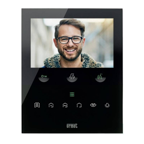
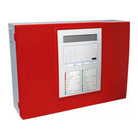
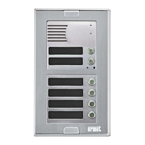
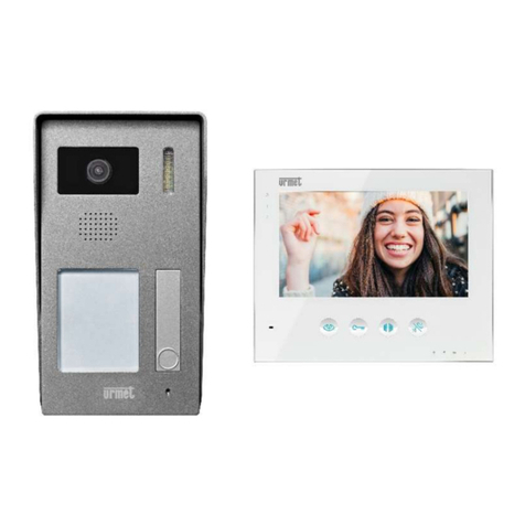
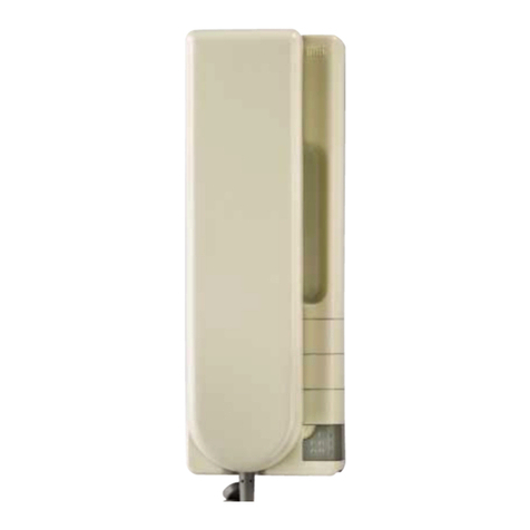
APARTMENT DOOR PHONE STATIONS
4
−−−−
sec.5a DIGIVOICE - Technical Manual
29 Clock key.
30 Main entrance door lock release key.
31 Secondary entrance door lock release key.
32 Voice channel switchover key: line to main entrance panel.
33 Error correction key.
34 Voice channel switchover key: main entrance panel to apartment
station.
35 Voice channel switchover key: line to apartment station.
36 Voice channel switchover key: line 1/ line 2.
37 Alphanumeric keypad. Used to enter call codes, door lock release
codes, self-activation codes and special service codes.
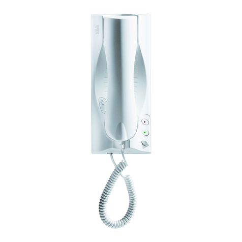
RINGER
The electronic warble tone ringer incorporates provision for adjusting
volume to MINIMUM, MEDIUM or MAXIMUM by means of lever (4)
located on the front of handset cradle section (6).
TYPES OF SERVICE
The guard door switchboard station’s operating mode depends on how
it is congured at the time of installation and on its current status. Up to
ve switchboard stations can be installed in the system. Depending on
their conguration, these switchboard stations can operate in parallel,
or can be assigned specic sections of the system.
A switchboard station can store two user code ranges in memory.
Together, these two ranges constitute a switchboard zone
assignment.
The switchboard station can intercept calls from main entrance panels
only if they are directed to apartment stations in its assigned zone.
In addition, the switchboard station can intercept calls made simply
by pressing the call button, or addressed to the switchboard station’s
code. Calls from apartment stations are intercepted only if the stations
concerned belong to the switchboard’s assigned zone. All switchboard
stations in the system can be assigned the same zones, in which case
they operate in parallel. Alternatively, switchboard stations may be
assigned different zones or zones that share certain codes.
Switchboard station operating modes are described below.
SWITCHBOARD STATION OFF
When the switchboard station is off, it behaves as if it were not present
in the system.
Calls originating from main entrance panels are sent directly to the
apartment stations; if the latter belong to the zone assigned to another
switchboard station, the calls may be intercepted by it. Calls originating
from apartment stations are not put through; again, if the apartment
stations involved belong to the zone assigned to another switchboard
station, the calls may be intercepted by it.
SWITCHBOARD STATION ON
When the switchboard station is turned on, it can be set up to operate
in either DAY or NIGHT service.
NIGHT SERVICE
In this operating condition, concierge service is disabled and calls
made from the main entrance panels are sent directly to the apartment
stations; if the latter belong to the zone assigned to another switchboard
station, the calls may be intercepted by it. Calls directed to the code
programmed in the switchboard station are intercepted by the station
if the latter is congured to do so.
The switchboard station can call any apartment station.
The switchboard station will normally receive calls from the apartment
stations only if they belong to its assigned zone. If desired, the
switchboard attendant can take these calls. If the attendant does not
answer the calls, they will be stored in memory. The switchboard
station can also be congured so that calls originating from apartment
stations are completely ignored. In this case, the switchboard station
will neither ring nor store the calls in memory.
Zone dddd (4 characters)
This is the zone used for codes entered by the switchboard attendant:
call codes, special codes, entrance module codes used for door lock
release of self-activation, etc. This zone can be cleared by mean of
the Xkey.
Zone dd/mm/yyyy hh:MM:ss (20 characters)
This zone normally displays date and time. It is also used temporarily
to indicate the zone assignments transferred from other switchboard
stations.
Zone CCCC (4 characters)
This zone shows the switchboard station code. It is also used
temporarily to display the codes for other switchboard stations during
the transition between Day and Night service.
Zone > T-ppp (6 characters)
This zone is used for door-open signaling and to indicate that the caps-
lock function has been activated to enter letter codes.
Tdesignates the type and ppp the code of the entrance module at
which the door is open.
Field Twill show:
Pfor main entrance panels
Sfor secondary entrance panels
The character >indicates that the CAPS-LOCK function is active (see
the paragraph headed ‘Call to apartment stations’).
Zone nn*rrrr! (8 characters)
This zone is used to display the calls or panic alarm signals received
from apartment stations which have been stored in the switchboard
station’s memory:
nn is the total number of calls or alarms in memory.
rrrr is the code for the apartment station in memory.
*indicates that code rrrr was the rst to be stored in
memory.
!indicates that apartment station rrrr made a panic alarm
call.
This zone is also used to display conrmation prompts when the
attendant attempts to delete codes from memory, and to indicate the
status of sensors connected to special decoders.
KEYPAD
The keypad features dual function number/letter keys used to enter
apartment station call codes, special codes, door lock release codes
and main entrance panel self-activation codes.
To enter a letter, hold down the

