manuals.online logo
Brands
  1. Home
  2. •
  3. Brands
  4. •
  5. Flex-a-Lite
  6. •
  7. Fan
  8. •
  9. Flex-a-Lite 30 User manual

Flex-a-Lite 30 User manual

1 of 2
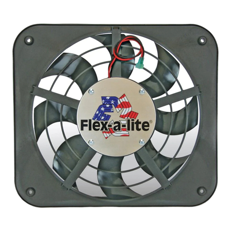
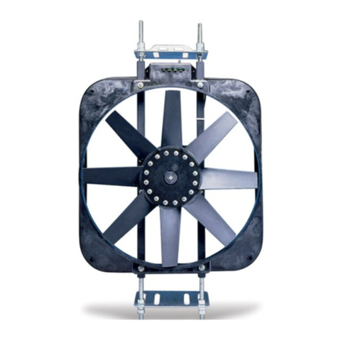
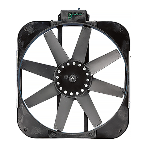
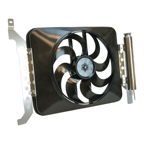
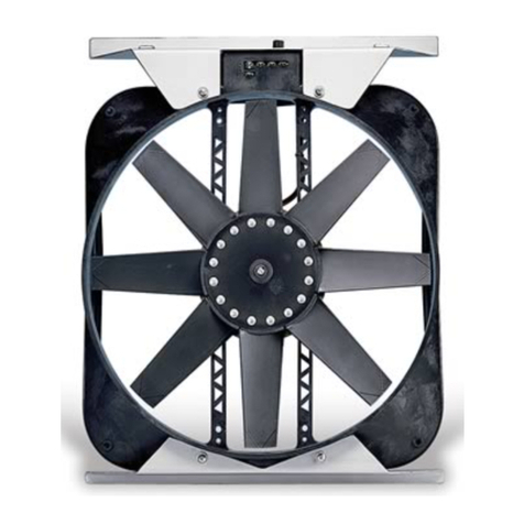
Model 30 or 35 Electric Fans
Model 30: Puller mode, includes thermostatic control.
Model 35: Puller mode, does not include controls.
Mounting Instructions--Model 30 or 35 may be
installed either horizontally or vertically to the radiator.
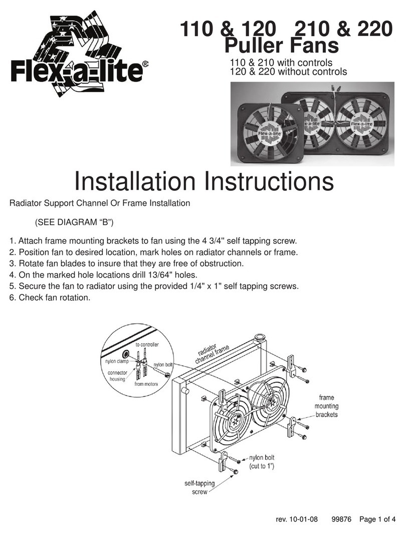
1. Remove the vehicle's existing fan and shroud.
2. Position the electric fan against the back of the radiator
(between the radiator & engine), and mark the holes for
mounting.
3. Rotate the blades to make sure they are free of obstructions.
4. With a small phillips screwdriver, pass through the marked
holes, carefully spreading the fins to allow easy passage for the
nylon bolts.Pass the bolts through the shroud holes then twist
the bolts through the radiator.
Important: If using a model 30, be sure the thermostatic
sensing bulb is touching the radiator.
5. Install rubber disc spacers, washers, and speed nut. Cut the
excess off the bolt (Leave enough excess for adjustments).
Diagram A
SpeedNut
Rectangular
RubberWasher
Plastic
Washer
NylonBolt
MandatoryConnections
+12 volt low amp source
GGround
OptionalConnection
MManual switch
B12 volt high amp
source
CAirconditioning relay
B
CMG+
In Line Fuse 12VoltLowAmpSource
1 2 3
Ground
3-way
Connector
12VoltSource
Ground(Illuminateswitch)
ControlBox
B
CMG+
Fusible en ligne
1 2 3
Terre
Connecteurà
3broches Boîtierdecontrôle
1 2 3
Cablepositivodelaire
acondicionado
Câblagesobligatoires
+Source12Vbasseintensité
GTerre
Câblagefacultatif
M Commutateur manuel
BSource12V haute
intensité
CRelaisdeclimatisation
Conexionesobligatorias
+Fuenta positiva de 12
voltios y bajo
amperaje
Conexiónopcional
MInterruptor manual
GTierra
BFuente de 12 voltios y
elevado amperaje
CRelé (relevador) de aire
acondicionado
B
CMG+
Fusible en línea
Tierra
Conectoren
tressentidos Cajadecontrol
Fil positif de climatisation
Source12 V basse intensité
Source12V
Terre (éclairage du commutateur)
Fuentede12voltios ybajo
amperaje
Fuente de 12 voltios
Tierra (iluminación del interruptor)
A/CPositiveLead
12Volt Positive
Source12 V (+)
Fuente de 12
voltios (+)
Optional Connection
Manual Switch(notincluded)—Allows manual
operationof fan (Note: based on Flex-a-lite’s manual
switchpart#31148)
1. Connect the “M” terminal to terminal 1 on the switch.
2. Attach terminal 2 to a 12 volt positive (+) source.
3. Attach terminal 3 to ground to illuminate switch.
Note (optional): To stop the fan from activating
thermostatically, omit the lead to the positive(+)
terminal of the control box. B, G, & M must remain
connected.
Mandatory Connections for Model 30
1. Disconnectbattery.
2. Connect the positive “+” terminal to a low amp 12 volt
positive(+)power source (e.g. fuse box), using the wire
providedinthekit.
Note(optional): Attach positive (+) terminal to an igni-
tion source to stop the fan unit from operating after the
engineis turned off.
3. Connect the “B” terminal to a high amp 12 volt positive (+)
power source,ie. positive (+)side of batteryor alternator,
usingthewireandinlinefuseincludedinkit.
4. Connect the “G” terminal to ground (ie. chassis, negative (-
)side of battery) using the wire providedin the kit.
5. Withthe wire and 3-way connector provided, spliceinto
theA/Cclutchpositive(+)wire. Connect the other end of
the wire to the "C" terminal of the control box. AirCondi-
tioning Relay Activates fan when A/C is turned on.
6. Installprovidedknobontothe thermostat shaft.
7. Adjustthermostattodesiredtemperaturewithin1800-2400.
2 of 2
Ventilateurs électriques, modèles 30 ou 35
Modèle30:modeàextraction,inclutcontrôlethermostatique.
Modèle 35 : mode à extraction, n’inclut pas de contrôles.
Instructions de montage — L’installation des modèletps 30 et
35 peut s’effectuer horizontalement ou verticalement par rapport
au radiateur.
1. Enlevez le ventilateur et la buse actuels du véhicule.
2. Placez le ventilateur électrique contre l’arrière du radiateur
(entre le radiateur et le moteur) et marquez les trous de
montage.
3. Tournez les pales du ventilateur pour vous assurer de l’absence
d’obstructions.
4. A l’aide d’un petit tournevis à tête étoilée, passez à travers les
trous marqués et écartez avec soin les ailettes pour faciliter le
passage des boulons en nylon. Faites passer les boulons dans
les trous de la buse, puis tordez-les à l’intérieur du radiateur.
Important : pour le modèle 30, assurez-vous que l’ampoule du
capteur thermostatique touche le radiateur.
5. Installez les pièce d’écartement en caoutchouc, puis les
rondelles et l’écrou rapide. Coupez l’excès du boulon (laissez-en
suffisamment pour les réglages.)
Câblages obligatoires pour le modèle 30
1. Débranchez la batterie.
2. Connectez la borne positive «+» à une source d’alimentation
positive (+) de 12 volts (par ex. une boîte à fusibles) basse
intensité. Utilisez pour ce faire le fil contenu dans le kit.
Remarque (facultatif) : connectez la borne positive (+) à la
source d’allumage pour empêcher le ventilateur de fonctionner
une fois que le moteur a été coupé.
3. Connectez la borne «B» à une source d’alimentation positive (+)
de 12 volts haute intensité, par exemple au côté positif (+) de la
batterie ou de l’alternateur. Utilisez pour ce faire le fil et le
fusible en ligne contenus dans le kit.
4. Connectez la borne «G» au côté terre (par ex. au châssis, côté
négatif (-) de la batterie). Utilisez pour ce faire le fil contenu
dans le kit.
5. Avec le fil de liaison et le connecteur à 3 broches fournis, faites
un raccord avec le fil positif (+) de l’embrayage de climatisation.
Reliez l’autre extrémité du fil à la borne «C» du boîtier de
contrôle.
Le relais de climatisation actionne le ventilateur quand vous
mettez la climatisation en marche.
6. Installez le bouton fourni sur l’axe du thermostat.
7. Réglez le thermostat à la température désirée, entre 82° C et
115° C (180° F et 240° F).
Câblage facultatif
Commutateur manuel (non inclus) — pour le
fonctionnement manuel du ventilateur
(Remarque : basé sur le commutateur manuel Flex-a-lite
n°31148)
1. Connectez la borne «M» à la borne 1 du commutateur.
2. Connectez la borne 2 à une source d’alimentation positive (+) de
12 volts.
3. Mettez la borne 3 à la terre pour éclairer le commutateur.
Remarque (facultatif) : pour empêcher le ventilateur de
s’actionner thermostatiquement, ne reliez pas le fil à la borne
positive (+) du boîtier de contrôle. B, G et M doivent rester
connectées.
2/96 99976
Ecrourapide
Rondelle en plastique
Rondelle
rectangulaire en
caoutchouc Boulonen nylon
Diagramme A Tuerca de
ajuste rápido
Arandela(roldana)
rectangular de caucho
Pernode nilón
Arandela(roldana)
de plástico
Diagrama A
Ventiladores eléctricos modelo 30 ó 35
Modelo30:Mododeextractor,concontroltermostáticoincluido.
Modelo 35: Mododeextractor,sincontroles incluidos.
Instrucciones de montaje - Los modelos 30 ó 35 se pueden
instalar ya sea horizontal o verticalmente en relación al radiador.
1. Retire la gualdera y el ventilador existente del vehículo.
2. Coloque el ventilador eléctrico apoyado en la parte posterior del
radiador (entre éste último y el motor) y marque los orificios de
montaje.
3. Haga girar las aspas para asegurarse de que no tengan
obstrucciones.
4. Con un destornillador Phillips pequeño, pase a través de los
orificios marcados, separando con cuidado las aletas para
permitir el paso fácil de los pernos de nilón. Haga pasar estos
últimos por los orificios de la gualdera y hágalos girar para que
atraviesen el radiador.
Importante: Si utiliza un modelo 30, asegúrese de que el bulbo
sensor termostático esté en contacto con el radiador.
5. Instale los espaciadores de discos de caucho, las arandelas y la
tuerca de ajuste rápido. Corte el exceso del perno (deje un tramo
suficiente para ajustes).
Conexiones obligatorias para el modelo 30
1. Desconecte la batería.
2. Conecte la terminal positiva “+” a una fuente de alimentación
positiva (+) de 12 voltios y bajo amperaje (por ejemplo, la caja de
fusibles), utilizando el cable que se proporciona en el estuche.
Nota (opcional): Acople la terminal positiva (+) a una fuente de
encendido para detener la unidad del ventilador después de que
se apague el motor.
3. Conecte la terminal “B” a una fuente de alimentación positiva (+)
de 12 voltios y elevado amperaje, o sea, en el lado positivo de la
batería o el alternador, utilizando el alambre y el fusible en línea
que se incluyen en el estuche.
4. Conecte la terminal “G” a tierra (por ejemplo, al chasis o el lado
negativo (-) de la batería), usando el alambre que se proporciona
en el estuche.
5. Con el alambre y el conector en tres sentidos que se incluyen,
haga un empalme en el alambre positivo (+) del embrague del
aire acondicionado. Conecte el otro extremo del alambre a la
terminal “C” de la caja de control.
El relé (relevador) del aire acondicionado activa el ventilador
cuando se enciende.
6. Instale la perilla proporcionada en el eje del termostato.
7. Ajuste el termostato a la temperatura deseada, entre 82° C y
115° C (180° F y 240° F).
Conexión opcional
Interruptor manual (no incluido) - Permite el funcionamiento
manual del ventilador (Nota: se basa en el el interruptor
manual Flex-a-lite, pieza número 31148).
1. Conecte la terminal «M» a la 1 del interruptor.
2. Acople la terminal 2 a una fuente positiva (+) de 12 voltios.
3. Fije la terminal 3 a tierra para iluminar el interruptor.
Nota (opcional): Para que el ventilador no se active
termostáticamente, omita el cable que va a la terminal positiva
(+) de la caja de control. B, G y M deberán permanecer
conectadas.

This manual suits for next models

1

Other Flex-a-Lite Fan manuals

Flex-a-Lite Low Profile Belt Fan User manual

Flex-a-Lite

Flex-a-Lite Low Profile Belt Fan User manual

Flex-a-Lite Black Magic Extreme 185 User manual

Flex-a-Lite

Flex-a-Lite Black Magic Extreme 185 User manual

Flex-a-Lite 285 User manual

Flex-a-Lite

Flex-a-Lite 285 User manual

Flex-a-Lite 318 User manual

Flex-a-Lite

Flex-a-Lite 318 User manual

Flex-a-Lite 292 User manual

Flex-a-Lite

Flex-a-Lite 292 User manual

Flex-a-Lite 775 User manual

Flex-a-Lite

Flex-a-Lite 775 User manual

Flex-a-Lite FLX-30118K Guide

Flex-a-Lite

Flex-a-Lite FLX-30118K Guide

Flex-a-Lite 125 User manual

Flex-a-Lite

Flex-a-Lite 125 User manual

Flex-a-Lite 130-Pusher User manual

Flex-a-Lite

Flex-a-Lite 130-Pusher User manual

Flex-a-Lite 678 User manual

Flex-a-Lite

Flex-a-Lite 678 User manual

Flex-a-Lite 314 User manual

Flex-a-Lite

Flex-a-Lite 314 User manual

Flex-a-Lite 272 User manual

Flex-a-Lite

Flex-a-Lite 272 User manual

Flex-a-Lite 10 User manual

Flex-a-Lite

Flex-a-Lite 10 User manual

Flex-a-Lite 110 User manual

Flex-a-Lite

Flex-a-Lite 110 User manual

Flex-a-Lite 32164K-Blade User manual

Flex-a-Lite

Flex-a-Lite 32164K-Blade User manual

Flex-a-Lite 115 User manual

Flex-a-Lite

Flex-a-Lite 115 User manual

Flex-a-Lite Trimline Electric Fans User manual

Flex-a-Lite

Flex-a-Lite Trimline Electric Fans User manual

Flex-a-Lite 130 User manual

Flex-a-Lite

Flex-a-Lite 130 User manual

Flex-a-Lite 130 User manual

Flex-a-Lite

Flex-a-Lite 130 User manual

Flex-a-Lite 365 User manual

Flex-a-Lite

Flex-a-Lite 365 User manual

Flex-a-Lite 390 User manual

Flex-a-Lite

Flex-a-Lite 390 User manual

Flex-a-Lite 295 User manual

Flex-a-Lite

Flex-a-Lite 295 User manual

Flex-a-Lite 278 User manual

Flex-a-Lite

Flex-a-Lite 278 User manual

Flex-a-Lite 290 User manual

Flex-a-Lite

Flex-a-Lite 290 User manual

Popular Fan manuals by other brands

LUCCI Air BREEZE 8 Installation, operation, maintenance & warranty information

LUCCI Air

LUCCI Air BREEZE 8 Installation, operation, maintenance & warranty information

Yard force LF C36 Original instructions

Yard force

Yard force LF C36 Original instructions

Olimpia splendid Caldo Whisper Instructions for installation, use and maintenance

Olimpia splendid

Olimpia splendid Caldo Whisper Instructions for installation, use and maintenance

Eglo STRADBROKE Installation Manual, Use & Care Guide

Eglo

Eglo STRADBROKE Installation Manual, Use & Care Guide

Fantasia Alpha Owner's instruction manual

Fantasia

Fantasia Alpha Owner's instruction manual

Sulion LIA manual

Sulion

Sulion LIA manual

RL R62402906 manual

RL

RL R62402906 manual

Fanimation Andover FP5220 Series owner's manual

Fanimation

Fanimation Andover FP5220 Series owner's manual

DAY 73212 instruction manual

DAY

DAY 73212 instruction manual

Joinco WN20082404 instruction manual

Joinco

Joinco WN20082404 instruction manual

Perel TV76502 user manual

Perel

Perel TV76502 user manual

Craftmade ELLINGTON E-BFT52ABZ5C installation guide

Craftmade

Craftmade ELLINGTON E-BFT52ABZ5C installation guide

emerio HFN-124770 instruction manual

emerio

emerio HFN-124770 instruction manual

Berbel BMK-F 125 installation instructions

Berbel

Berbel BMK-F 125 installation instructions

Schako PA-R Mounting instructions

Schako

Schako PA-R Mounting instructions

Brink Flair 325 Installation regulations

Brink

Brink Flair 325 Installation regulations

PAX Mistral iV12t Installation and operating instructions

PAX

PAX Mistral iV12t Installation and operating instructions

Aerovent IM-166 Installation, operation & maintenance manual

Aerovent

Aerovent IM-166 Installation, operation & maintenance manual

manuals.online logo
manuals.online logoBrands
  • About & Mission
  • Contact us
  • Privacy Policy
  • Terms and Conditions

Copyright 2025 Manuals.Online. All Rights Reserved.