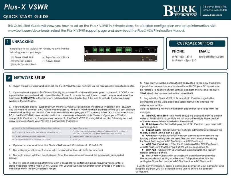
Eurofyre CRISIS User manual

EVC Network Expander
Installation Guide
Date: July 2020
Document: EF.CRISISEVCNEIG
Issue: 1.0
www.eurofyre.co.uk

This page is intentionally left blank.

Crisis EVC Network Expander Installation Guide
Page 3
www.eurofyre.co.uk
Intellectual Property and Copyright
This document includes registered and unregistered trademarks. All trademarks displayed are the trademarks of their respective owners. Your use
of this document does not constitute or create a licence or any other right to use the name and/or trademark and/or label.
This document is subject to copyright owned by Eurofyre Limited. You agree not to copy, communicate to the public, adapt, distribute, transfer,
sell, modify or publish any contents of this document without the express prior written consent of Eurofyre.
Disclaimer
The contents of this document is provided on an “as is” basis. No representation or warranty (either express or implied) is made as to the
completeness, accuracy or reliability of the contents of this document. The manufacturer reserves the right to change designs or specifications
without obligation and without further notice. Except as otherwise provided, all warranties, express or implied, including without limitation any
implied warranties of merchantability and fitness for a particular purpose are expressly excluded.
General Warning
This product must only be installed, configured and used strictly in accordance with the General Terms and Conditions, User Manual and
product documents available from Eurofyre. All proper health and safety precautions must be taken during the installation, commissioning and
maintenance of the product. The system should not be connected to a power source until all the components have been installed. Proper safety
precautions must be taken during tests and maintenance of the products when these are still connected to the power source. Failure to do so
or tampering with the electronics inside the products can result in an electric shock causing injury or death and may cause equipment damage.
Eurofyre is not responsible and cannot be held accountable for any liability that may arise due to improper use of the equipment and/or failure to
take proper precautions. Only persons trained through an Eurofyre accredited training course can install, test and maintain the system.
Liability
You agree to install, configure and use the products strictly in accordance with the Installation, User Manuals and product documents available
from Eurofyre.
Eurofyre is not liable to you or any other person for incidental, indirect, or consequential loss, expense or damages of any kind including without
limitation, loss of business, loss of profits or loss of data arising out of your use of the products. Without limiting this general disclaimer the
following specific warnings and disclaimers also apply:
Fitness for Purpose
You agree that you have been provided with a reasonable opportunity to appraise the products and have made your own independent
assessment of the fitness or suitability of the products for your purpose. You acknowledge that you have not relied on any oral or written
information, representation or advice given by or on behalf of Eurofyre or its representatives.
Total Liability
To the fullest extent permitted by law that any limitation or exclusion cannot apply, the total liability of Eurofyre in relation to the products is limited
to:
In the case of services, the cost of having the services supplied again; or
In the case of goods, the lowest cost of replacing the goods, acquiring equivalent goods or having the goods repaired.
Indemnification
You agree to fully indemnify and hold Eurofyre harmless for any claim, cost, demand or damage (including legal costs on a full indemnity basis)
incurred or which may be incurred arising from your use of the products.
Miscellaneous
If any provision outlined above is found to be invalid or unenforceable by a court of law, such invalidity or unenforceability will not aect the
remainder which will continue in full force and eect. All rights not expressly granted are reserved.

Crisis EVC Network Expander Installation Guide
Page 4 www.eurofyre.co.uk
Scope
The Crisis EVC Network Expander Installation Guide provides a comprehensive description of the Crisis Emergency Voice Communication System.
This guide introduces the Crisis EVC Expander features, technical specifications and gives an understanding of its components and their function.
You will also find instructions on installing, configuration and testing.
This guide is for anyone involved with the design, maintenance and purchasing of a Crisis EVC system. It is assumed that anyone using this
product has the knowledge and appropriate certification from local fire and electrical authorities.
Document Conventions
The following typographic conventions are used in this document:
Convention Description
Bold Used to denote: Emphasis.
Italics Used to denote: References to other parts of this document or other documents.
The following icons are used in this document:
Convention Description
Recommended guideline: Advising to do so.
Caution: Not appropriate to do so or; care taken to avoid danger or mistakes.
Contact Us
Telephone +44 (0) 1329 835 024
Email [email protected]
Website www.eurofyre.co.uk

Crisis EVC Network Expander Installation Guide
Page 5
www.eurofyre.co.uk
1 Introduction...........................................................................................................................................6
1.1 What is an Emergency Voice Communication System?...........................................................6
1.2 Suitability...............................................................................................................................................6
2 Product Overview ................................................................................................................................6
3 Important Safety Information.............................................................................................................7
3.1 Unpacking.............................................................................................................................................8
4 Installation.............................................................................................................................................9
4.1 Connecting the Crisis EVC Network Expander ..........................................................................9
4.2 Planning the Wiring............................................................................................................................9
4.3 Cable and Wiring Guidance........................................................................................................... 10
4.4 Cabling Methods............................................................................................................................... 10
4.5 Battery Information........................................................................................................................... 12
4.6 Outstation Connections ...................................................................................................................13
4.7 Auxiliary Connections.......................................................................................................................14
4.8 Powering Up Procedure ..................................................................................................................14
4.9 Powering Down Procedure.............................................................................................................14
5 Hardware Configuration Procedure ............................................................................................... 15
5.1 Network Expander Exchange PCB Dipswitch Settings .......................................................... 16
6 Indications .......................................................................................................................................... 17
6.1 Mode Indicator Summary ................................................................................................................17
6.2 Power Supply & CPU indicator Summary................................................................................... 18
6.3 Zone Indicator Summary ................................................................................................................ 18
7 Commissioning Procedure............................................................................................................... 19
8 Maintenance ....................................................................................................................................... 19
Notes............................................................................................................................................................. 20
9 Technical Specification ..................................................................................................................... 21
Table Of Contents

Crisis EVC Network Expander Installation Guide
Page 6 www.eurofyre.co.uk
1 Introduction
1.1 What is an Emergency Voice Communication System?
An Emergency Voice Communication System, or EVCS, is a system that allows voice communication in either direction between a central control
point and a number of other points throughout a building or building complex, particularly in a fire emergency situation. The control points, or
outstations by which they are more commonly referred, generally comprise of a Type A outstation, a Type B outstation, or a Type C Combined
Type outstation. “Assist Call” emergency assistance alarm systems can also be incorporated into the EVCS.
EVCS is generally required in the following situations:
• In any building or sports or similar venue where there are disabled people, or people who may have diculty negotiating the evacuation
route.
• In buildings with phased evacuation and/or fire fighting lifts where it facilitates secure communications for building managers, fire wardens,
and attending fire ocers.
• At sports venues and similar complexes, where it will assist stewards in controlling the evacuation of the area in an emergency.
The Crisis Emergency Voice Communications System (EVCS) is designed to fully comply with BS5839 Part 9:2011 for use as a Fire Telephone
system, Disabled Refuge Call system or as a combined system when both Fire Telephones and Disabled Refuge Points are required.
1.2 Suitability
Fire telephone systems are recommended for all public buildings and multi-story buildings over four floors by BS9999.
Disabled Refuge systems are required in buildings where the public or disabled sta gains access to any floor other than the ground floor using
lifts. Refuge areas are provided at each storey exit from each protected stairway.
2 Product Overview
The Crisis EVC System has been designed around a total network concept so all of the Crisis EVC panels have inbuilt networking.
The system comprises 3 types of panel; Crisis EVC Network Master Station, the Crisis EVC Master Station (2 to 8 lines) and a Crisis EVC Network
Expander Panel. For Crisis systems in excess of 8 lines a EVC Network Mater Station MS must be used as the master station, the system can then
be expanded by the use of an EVC Expander Panel or EVC Master Station in blocks of 8 lines up to a maximum system capacity of 512 lines.
Additional EVC Network Master Stations can be used wherever indication and control is required, i.e. fire control rooms and building reception.
These additional EVC Network Master Stations have the facility to filter the information that is displayed, so if there are several buildings with a
EVC Network Master Station in each building, the EVC Network Master Station can be configured to only display/answer EVCS calls from that
building. The system also has the ability for all calls to be displayed/answered on a particular EVC Network Master Station thus becoming the
overall site master. This display filter can also be applied to “Assist Call” indications so panels can be configured to only display/acknowledge calls
from “Assist Call” emergency assistance alarms. This display filtering works in exactly the same manner as for EVCS calls.
Each EVC Network Master Station can be configured so information displayed during daytime is distinct from information displayed during night
time, thus allowing separate locations to handle daytime operations and night-time operations. The day/night timing applies across the entire
network.
The Crisis EVC Network Master Stations are able to call individual outstations via a named directory list or by dialling the appropriate extension
number for the desired outstation. In addition to this it is possible to call from one EVC Network Master Station to another so communication
between master stations is possible and control can be transferred between master stations.
The wiring is a ring and spur topology with outstations being wired on radial spurs from any master station or system expander panel. The EVC
Network Expander and any EVC Network Master Station or EVC Master Station are wired in a ring network up to a maximum of 64. The EVC
Network Expander would typically be sited in convenient locations close to the outstations i.e. risers or stairwells resulting in short vertical wiring
runs. The EVC Master Station can be used to provide local control of up to 8 lines within a building this can then report back to a Crisis EVC
Network Master Station which can provide overall control of an entire site. In this way a very large system can be completed with a minimum of
cabling coming back the master station via the network ring.
Additionally the “Assist Call” emergency assistance alarm system can either be connected to the same line with an outstation, or connected
to a dedicated line. As each line is powered from the EVC Network Master Station or EVC Network Expander, the outstations and the “Assist
Call” emergency assistance alarm system do not require a separate power supply unit. This has the additional benefit of each line being fully
monitored and battery backed up.

Crisis EVC Network Expander Installation Guide
Page 7
www.eurofyre.co.uk
3 Important Safety Information
This Equipment must only be installed and maintained by a suitably skilled and competent person.
This Equipment is defined as Class 1 in EN60065 (Low Voltage Directive) and must be EARTHED.
Caution: Indoor Use Only
Warning: Shock Hazard - Isolate Before Opening
Warning: TO REDUCE THE RISK OF FIRE OR ELECTRIC SHOCK, DO NOT EXPOSE THIS UNIT TO RAIN OR MOISTURE
Warning: THIS UNIT MUST BE EARTHED
Warning: NO USER SERVICEABLE PARTS
Each Crisis EVC Network Master Station or EVC Network Expander Panel requires a 3A spur, returning to a breaker clearly marked “EVCS DO
NOT TURN OFF”.
If the Crisis EVC Network Master Station and the Crisis EVC Network Expander are distributed around a site, it is essential that both Crisis Stations
are on the same mains phase, as they are classified TEN 230V. Powering from dierent phases can mean a 440V potential can be present in a
Crisis EVC Station during a major fault incident.
Anti-static handling guidelines
Make sure that electrostatic handling precautions are taken immediately before handling PCBs and other static sensitive components.
Before handling any static-sensitive items, operators should get rid of any electrostatic charge by touching a sound safety earth. Always handle
PCBs by their sides and avoid touching any components.

Crisis EVC Network Expander Installation Guide
Page 8 www.eurofyre.co.uk
3.1 Unpacking
Remove the Crisis EVC Network Expander from its packing, and check the contents against the following list:
• Crisis EVC Network Expander
• Installation Guide
• Accessory Pack:
1 x 2.5mm AF Hex Key
8 x 10k End of Line (EOL) Resistors
Installation Guide
Figure 1: Crisis EVC Network Expander Front
Use the 2.5mm AF Hex Key supplied to open the right-hand front cover.
Verify the following items are present:
• 4 x Line Cards
• 1 x 3-way Mains Connector
• 1 x 2-way Fault Connector
• 1 x 2-way In Use Connector
• 1 x 2-way Enable Connector
• 4 x 2-way Network Connectors
• 1 x Battery Lead
If there are any items missing, please contact your supplier or Eurofyre Limited, quoting the unit serial number and the name on the packing list
enclosed, so the situation can be rectified.

Crisis EVC Network Expander Installation Guide
Page 9
www.eurofyre.co.uk
4 Installation
4.1 Connecting the Crisis EVC Network Expander
To comply with EMC (Electro Magnetic Compatibility) regulations and to reduce the risk of electrical interference in the system wiring, the use of
fire-resistant screened cables is recommended throughout the installation.
All wiring should come into the enclosure via the knockouts provided, and be fixed tidily to the relevant terminals.
Correct cable glanding is essential. Due regard should be paid to any system specifications which demand a certain cable type,
providing it meets the appropriate national wiring regulations.
Figure 2: Crisis EVC Network Expander Internals
Prior to mounting the Crisis EVC Network Expander, it should be decided if the field wiring is to be run on the surface or concealed. There are 14
knockouts on the top and 2 slotted entries with a dedicated mains supply entry at the rear. If a knockout is removed by mistake, fill the hole with a
good quality cable gland.
Net IN
A + B
Net IN
C + D
Net OUT
A + B
Net OUT
C + D
Line 1
Line 2
Line 3
Line 4
Line 5
Line 6
Line 7
Line 8
Mains
Fault/
Enable
Figure 3: Crisis EVC Network Expander Top Entries
Unused knockouts must be left unopened to comply with the Low Voltage Directive. Accidentally knocked out holes should be blanked o.
The Crisis EVC Network Expander weighs 5kg with batteries, so care should be taken to securely mount the Station on stud walling.
4.2 Planning the Wiring
All system wiring should be installed to meet the appropriate parts of BS5839 Part 9:2011 and BS 7671 (Wiring Regulations). Other national
standards of installation should be adhered to where applicable.
Do not test wiring using an insulation tester (Megger) with any equipment connected, as the 500 Volt test voltage will destroy these
devices.
You must observe local wiring regulations. Do not run SELV and LV cables in the same enclosure without adequate insulation between them.

Crisis EVC Network Expander Installation Guide
Page 10 www.eurofyre.co.uk
4.3 Cable and Wiring Guidance
4.3.1 Fire Telephone System
Any system using Type A outstations must use enhanced grade cabling throughout for all wiring, including the mains supply to the Crisis EVC
Network Expander.
4.3.2 Disabled Refuge EVC System
For buildings less than 30m in height, or any building with sprinklers fitted, standard grade fire resistant cable may be used to wire Type B
outstation and the mains supply to the Master Controller; as long as the planned evacuation will be completed in 30 minutes.
If the building is over 30m in height without sprinklers, or where the evacuation will take place over multiple stages exceeding 30 minutes, then
enhanced grade cables must be used.
4.3.3 Combined Systems
For systems containing Type A, Type B or Type C outstations, shared cable such as network cables must be enhanced grade.
Cabling to Type A or Type C outstations must be in enhanced grade fire resistant cabling. Individual spurs to Type B outstations can be wired in
standard grade fire resistant cabling in accordance with the wiring guidelines already set out for disabled refuge systems.
4.3.4 “Assist Call” Emergency Assistance Alarm Systems
All installations must conform to Building Regulations Approved Document M. The “Assist Call” is wired using 2 core cable, and the “Assist Call”
plates can be wired in any order.
4.4 Cabling Methods
There are 3 cabling methods available:
• Connection to a Type A or Type C outstation: use 2 core enhanced grade fire resistant cable when extending a firefighting telephone system.
• Connection to a Type B outstation: use 2 core standard grade fire resistant cable when extending a disabled refuge system.
• Connection to an “Assist Call” system on a dedicated line requires 2 core 1mm CSA or above PVC sheathed.
4.4.1 Crisis EVC Network Expander Wiring
The wiring for a Crisis EVC Network Expander is shown in the schematic below.
1 o 2 Core 1.5mm CSA
Standard Rated Fire Cable
1 o 2 Core 1.5mm CSA
Enhanced Rated Fire Cable
1 o 2 Core 1mm CSA
Standard PVC Minimum
Accessible Toilet
Fire Telephone
Disabled Refuge
Accessible Bedroom
Figure 4: Typical Wiring Diagram - Crisis EVC Network Expander

Crisis EVC Network Expander Installation Guide
Page 11
www.eurofyre.co.uk
4.4.2 Crisis EVC Network Master Station & Expander Panel - Ring Wiring
If more than 8 lines are required then an Expander Panel will be required in addition to the EVC Network Master Station, with the outstations
shared between both the EVC Network Master Station and the Expander Panel. The system has to be wired as a ring as shown in the schematic
below. This ensures that the loss of any single cable will not aect the operation of more than one outstation.
1 o 2 Core 1.5mm CSA
Standard Rated Fire Cable
1 o 2 Core 1.5mm CSA
Enhanced Rated Fire Cable
1 o 2 Core 1mm CSA
Standard PVC Minimum
Network 2 o 2 Core 1.5mm
CSA Standard Fire Rated
Cable unless Type A or
Type C Outstations are used,
then it must be Enhanced.
Figure 5: Typical Ring/Network Wiring Diagram - Crisis EVC Network Master Station & Expander

Crisis EVC Network Expander Installation Guide
Page 12 www.eurofyre.co.uk
4.4.3 Crisis EVC Network Connections
A B
C D
A B
C D
A B
C D
A B
C D
Figure 6: Typical Network Connection Diagram - Crisis EVC Network Expander
Only connect the earth screens on the Net in cables, cut back and insulate Net OUT earth screens.
4.4.4 Mains Connection
Each Crisis EVC Network Master Station, EVC Network Expander Panel and EVC Master Station requires a 3A spur, returning to a breaker clearly
marked “EVCS DO NOT TURN OFF”.
If the Master Stations and Expander Panel are distributed around a site, it is essential that both panels are on the same mains phase, as they are
classified TEN 230V. Powering from dierent phases can mean a 440V potential can be present in a Station during a major fault incident.
4.5 Battery Information
In the event of mains failure BS5839 Part 9:2011 requires battery backup for 24 hours standby and 3 hours operation thereafter.
A Crisis EVC Network Expander requires one number 12V 7AH vent regulated sealed lead acid battery. The battery is not supplied with the Master
Station.
Safety Information:
Sealed Lead Acid batteries contain sulphuric acid which can cause burns if exposed to the skin. The low internal resistance of these
batteries mean large currents will flow if they are accidentally short-circuited causing burns and a risk of fire. Exercise caution when
handling batteries.
Power Up Procedure:
Always apply mains power before connecting batteries. When connecting batteries, always connect the Positive (Red +) terminal first.
Power Down Procedure
Disconnect the batteries before removing the mains power. When disconnecting batteries, always remove the Negative (Black – )
terminal first.

Crisis EVC Network Expander Installation Guide
Page 13
www.eurofyre.co.uk
4.6 Outstation Connections
The Crisis EVC Network Master Station and EVC Network Expander Panel are configured via the configuration spreadsheet contained on the
Micro SD Card supplied with the Master Station, for configuration see section 6.
The following devices are available on the system:
• Type A (fixed phone)
• Type B (hands-free refuge point)
• Type C “Combi” (combined Type A and Type B)
• Jack Point
• “Assist Call” emergency assistance alarm system
For Type A, Type B, and Type C outstations, the end-of-line 10kΩ resistor should be removed from the accessory pack and connected to the end-
of-line terminal in the outstation.
For Jack points and the “Assist Call” system, the end-of-line 10kΩ resistor should also be removed from the accessory pack and connected to the
last plate on the system.
4.6.1 Type A Outstation
Line Card
in Master
Station
EOL resistor fitted if Line unused
Figure 7: Type A Outstation Wiring Diagram
The Earth screen should be sleeved and connected to the terminal block in the controller, and the earth stud in the Type A outstation.
4.6.2 Type B Outstation
Line Card
in Master
Station
EOL resistor fitted if Line unused
Figure 8: Type B Outstation Wiring Diagram
The Earth screen should be sleeved and connected to the terminal block in the controller, and the earth connection in the metal back
box (if a plastic back-box is used cut the earth back and insulate at the outstation).

Crisis EVC Network Expander Installation Guide
Page 14 www.eurofyre.co.uk
4.6.3 ACA Accessible Toilet Kit
Line Card
in Master
Station
EOL resistor fitted if Line unused
Figure 9: ACA Accessible Toilet Kit Wiring Diagram
The “Assist Call” ACA kit comprises an Over Door Indicator, a Pull Cord, and a Cancel Plate. The above order is a typical order; with the Over Door
Indicator, Pull Cord and the Cancel Plate connected as shown, but the plates can be wired in any order as long as the EOL resistor goes into the
free terminal of the last plate.
4.6.4 Enable Switch Input
The Enable Switch Input is used for the remote enabling or disabling of panels, it connects to a spare line input in either a Crisis Master Station
or System Expander. A typical application would be a sports stadium which requires control to switch to the match control room during the event.
The input is monitored and expects a 470R resistor for activation, not supplied (a fire alarm manual call point may be used) The 10K EOL resistor is
as supplied with the panel.
4.7 Auxiliary Connections
Figure 10: Auxiliary Connections
The Crisis EVC Network Expander has three auxiliary connections:
Fault is a normally closed volt free relay (30V DC 1A) which OPENS on any fault, including loss of power.
In Use is a normally open volt free relay (30V DC 1A) connection which closes when any outstation is operated, see Remote Signal Display section
7.7 switch settings for further information.
Enable is a normally CLOSED input and is required to operate the system, this is often connected to the fire alarm system. If Jumper J9 is in
place, then no connection is required at the terminals. This function only disables Type B outstations, with Type A outstations and “Assist Call”
emergency assistance alarm systems continuing to operate. Calls from Type B outstations automatically “time out” after approximately 30 minutes.
It is advised that this feature is not used as the system should always be available, not just during an evacuation. If the feature is used, then the
mode LED illuminates yellow after 30 seconds to show that the system is disabled.
If the system is disabled, the master station can still make outgoing calls.
If this function is used, it only requires connection with one panel on the network. If the Enable Input is CLOSED on one panel, then all panels on
the network are CLOSED. To disable Type B outstations, then the Enable Input on all panels on the network must be OPEN.
4.8 Powering Up Procedure
Before powering up the EVC Network Expander, carefully check all internal wiring.
1. Apply mains power first.
2. Connect the battery using the battery leads supplied. Always connect the Positive (Red + ) terminal first before connecting the Negative
(Black - ) terminal.

Crisis EVC Network Expander Installation Guide
Page 15
www.eurofyre.co.uk
4.9 Powering Down Procedure
To power down the Crisis EVC Network Expander:
1. Disconnect the battery. Always disconnect the Negative (Black - ) terminal first, before disconnecting the Positive (Red + ) terminal.
2. Remove mains power.
5 Hardware Configuration Procedure
The Crisis range of panels has in-built networking. This is described in the product overview section. Install the additional panel/station as per the
relevant parts in the installation section 4.
Any panels on the network must be wired as a ring (see 4.4.1 and 4.4.2). This is due to the ability for outstations to be wired from any panel
therefore there is no loss of functionality due to cable faults as a ring provides redundancy.
Network connections used are Network Out and Network In, with Network In on one Station wired to Network Out on the other Station (A to A, B
to B, C to C, and D to D).
The default network address setting for the Crisis Network Expander is 2.
When adding a Network Expander, it must have a unique network address, and must be included in the site configuration file (see section 6 of the
Crisis EVC Network Master Station Installation Guide).
If the site configuration is not updated the panel will not be seen by the rest of the network and importantly any outstations connected to that
panel will not operate as they will not be seen by the rest of the network.

Crisis EVC Network Expander Installation Guide
Page 16 www.eurofyre.co.uk
5.1 Network Expander Exchange PCB Dipswitch Settings
The Crisis network is formed from EVC Network Master Stations, Expander Panels, and EVC Master Stations. Each panel on the network has
to have a unique network address. This address is set by the dipswitches on the Exchange PCB. The address is a binary number given by the
positions of dip switches 1 to 6, with valid addresses lying between 1 and 64 inclusive.
Addr 1 2 3 4 5 6 Addr 1 2 3 4 5 6
1 OFF ON ON ON ON ON 33 OFF ON ON ON ON OFF
2 ON OFF ON ON ON ON 34 ON OFF ON ON ON OFF
3 OFF OFF ON ON ON ON 35 OFF OFF ON ON ON OFF
4 ON ON OFF ON ON ON 36 ON ON OFF ON ON OFF
5 OFF ON OFF ON ON ON 37 OFF ON OFF ON ON OFF
6 ON OFF OFF ON ON ON 38 ON OFF OFF ON ON OFF
7 OFF OFF OFF ON ON ON 39 OFF OFF OFF ON ON OFF
8 ON ON ON OFF ON ON 40 ON ON ON OFF ON OFF
9 OFF ON ON OFF ON ON 41 OFF ON ON OFF ON OFF
10 ON OFF ON OFF ON ON 42 ON OFF ON OFF ON OFF
11 OFF OFF ON OFF ON ON 43 OFF OFF ON OFF ON OFF
12 ON ON OFF OFF ON ON 44 ON ON OFF OFF ON OFF
13 OFF ON OFF OFF ON ON 45 OFF ON OFF OFF ON OFF
14 ON OFF OFF OFF ON ON 46 ON OFF OFF OFF ON OFF
15 OFF OFF OFF OFF ON ON 47 OFF OFF OFF OFF ON OFF
16 ON ON ON ON OFF ON 48 ON ON ON ON OFF OFF
17 OFF ON ON ON OFF ON 49 OFF ON ON ON OFF OFF
18 ON OFF ON ON OFF ON 50 ON OFF ON ON OFF OFF
19 OFF OFF ON ON OFF ON 51 OFF OFF ON ON OFF OFF
20 ON ON OFF ON OFF ON 52 ON ON OFF ON OFF OFF
21 OFF ON OFF ON OFF ON 53 OFF ON OFF ON OFF OFF
22 ON OFF OFF ON OFF ON 54 ON OFF OFF ON OFF OFF
23 OFF OFF OFF ON OFF ON 55 OFF OFF OFF ON OFF OFF
24 ON ON ON OFF OFF ON 56 ON ON ON OFF OFF OFF
25 OFF ON ON OFF OFF ON 57 OFF ON ON OFF OFF OFF
26 ON OFF ON OFF OFF ON 58 ON OFF ON OFF OFF OFF
27 OFF OFF ON OFF OFF ON 59 OFF OFF ON OFF OFF OFF
28 ON ON OFF OFF OFF ON 60 ON ON OFF OFF OFF OFF
29 OFF ON OFF OFF OFF ON 61 OFF ON OFF OFF OFF OFF
30 ON OFF OFF OFF OFF ON 62 ON OFF OFF OFF OFF OFF
31 OFF OFF OFF OFF OFF ON 63 OFF OFF OFF OFF OFF OFF
32 ON ON ON ON ON OFF 64 ON ON ON ON ON ON
Table 1: Crisis Network Expander Exchange PCB Dip Switch Settings
Dipswitch 7 and 8 are reserved for future expansion.

Crisis EVC Network Expander Installation Guide
Page 17
www.eurofyre.co.uk
6 Indications
Figure 11: Crisis EVC Network Expander Indication
6.1 Mode Indicator Summary
Mode Description
Green Solid Normal state
Red Solid Outstation o hook
Blue Solid Assist call active
Yellow Solid Type B disable function active (Enable jumper open)
Table 2: Indicator Summary

Crisis EVC Network Expander Installation Guide
Page 18 www.eurofyre.co.uk
6.2 Power Supply & CPU indicator Summary
AC DC PSU CPU Description
ON Mains OK
OFF ON Mains failure
ON ON Battery OK
ON OFF FLASH Battery open circuit
ON OFF ON Battery short circuit
ON FLASH ON Battery high impedance
ON ON ON PSU processor fail
ON ON Display or Exchange Processor Fault or Display-Exchange comms fault
Table 3: Power Supply & CPU Indicator Summary
ON = LED illuminated
OFF = LED o
FLASHING = LED Flashing
The general fault LED flashes on all fault conditions until accepted at the master station, when accepted the LED goes solid.
6.3 Zone Indicator Summary
Zone Indicator Status Description
Slow Flashing Red Outgoing call
Fast Flashing Red Incoming call from type A outstation
Normal Flashing Red Incoming call from type B outstation
Normal Flashing Green Call connected to local master handset
Normal Flashing Green/Red Call on hold
Solid Yellow Line Short circuited
Slow Flashing Yellow Line card missing
Normal Flashing Yellow Line Open circuit or EOL missing
Fast Flashing Yellow Line Earth fault
Normal Flashing Blue Incoming Assist Call alarm
Solid Blue Assist call acknowledged
Table 38: Zone Indicator Summary
The general fault LED flashes on all fault conditions until accepted at the master station, when accepted the LED goes solid.

Crisis EVC Network Expander Installation Guide
Page 19
www.eurofyre.co.uk
7 Commissioning Procedure
• The commissioning should be carried out by a competent person who has a basic knowledge and understanding of the design and
installation sections of BS5839-9:2011, and has access to the specification of the project.
• The 500v insulation tests should have been carried out by the installer and the results made available to the commissioning engineer.
• All cables should be correctly labelled.
• Test field wiring and check for end-of-line 10KΩ resistor. Check cables are clear from any short or open circuits.
• Connect outstation cables into Line Cards ensuring the Earth is sleeved and terminated into the Earth block.
• Configure relevant dipswitches for the network settings that may be required as per the set up section in this manual.
• Connect the network cabling (if appropriate), ensuring Net OUT ABCD is correctly connected to Net IN ABCD and the ring is continuous.
Only Connect the Earth screen of the Net IN cables.
• Power up the Crisis EVC Network Expander using mains only, fed from a 3A fuse fitted in an unswitched fused spur. The AC power indicator
will be illuminated, and the DC power indicator is extinguished. The PSU fault and General fault indicators will be illuminated. There should
be no line fault indicators illuminated.
• If there are no line faults present, the battery may be connected. The DC power indicator will be illuminated, and the PSU fault and General
fault indicators are extinguished when battery is connected.
• If there are any line fault indicators illuminated, then the field wiring should be checked prior to the battery being connected.
• Repeat the power up section for any additional Expander panels or additional EVC Master Stations.
• Upload the site configuration from the Micro SD Card (recommended) or using the menus.
• If device missing or network faults are reported address these before continuing. Once remedied re-upload the site configuration to ensure
all panels are programmed.
• Lift the master handset receiver and listen for a cadence tone.
• All outstations may be tested now, visit each outstation in turn and test that it is connected to the correct Master Station or Expander panel
and perform an intelligibility test. This test should be conducted when the building has normal background noise levels. The intelligibility test
requires two personnel.
• Where Assist Call is fitted, all pull cords in each circuit should be tested, acknowledged at the panel, cancelled at the call location and the
panel text checked. Ensure all controls and indicators operate correctly.
• When all outstation tests are complete, network cable checks should be performed to ascertain correct operation by unplugging network
cable to ensure the network is correctly fault monitoring and continues to work with a single cable fault.
• When complete the log may be retrieved from Micro SD Card, saved as a spreadsheet and kept for record purposes.
8 Maintenance
It is a requirement of BS 5839-9:2011 that a maintenance agreement be in place for the EVCS. The maintenance schedule should be as follows:
Frequency Test
Weekly Test a dierent outstation on the system each week and make a call to the control. Repeat each week until all outstations and
master stations are tested. Record these results in the site log. *If more than one master station is present alternate weekly.
Biannually Engineer call to check system operation, intelligibility, field strength of attached AFILS equipment and check battery health.
Record results and any variations into the site Log Book
Yearly Engineer call to check system operation perform 100% outstation and master station operation, field strength of attached AFILS
equipment and check battery health. Record results and any variations into the site Log Book
5 Yearly In addition to Yearly tests replace all batteries and record in Log Book.
Table 39: Maintenance

Crisis EVC Network Expander Installation Guide
Page 20 www.eurofyre.co.uk
Notes
Other manuals for CRISIS
1
Table of contents
Popular Network Hardware manuals by other brands

SonicWALL
SonicWALL ECLASS NSA E5500 Getting started guide

Citrix
Citrix NetScaler 9010 Platform quick start guide

TP-Link
TP-Link TL-PA8033P Quick installation guide

Spirent
Spirent DLS 6700 operating manual

Cisco
Cisco VPN 3002 Hardware Client Manager quick start guide
ZyXEL Communications
ZyXEL Communications IES-6000 - ANNEXE 749 Brochure & specs

Precision Digital Corporation
Precision Digital Corporation PDW30 quick start guide

NETWEEN
NETWEEN NVR Quick installation guide

Huawei
Huawei NE-HIC-2xFE Specifications
Telemate
Telemate NetSpective Hardware installation guide

WBOX Technologies
WBOX Technologies 0E-4CHNVR2TB user manual
Datacom Systems
Datacom Systems Tap Series Fast start guide
