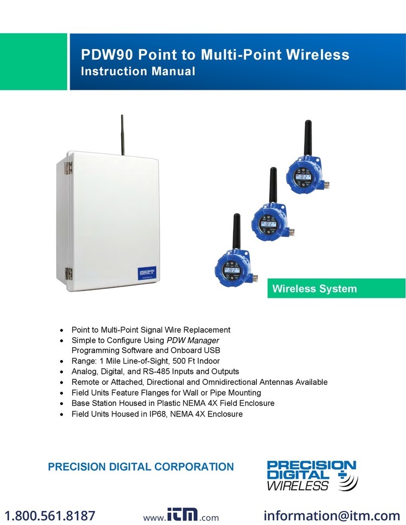
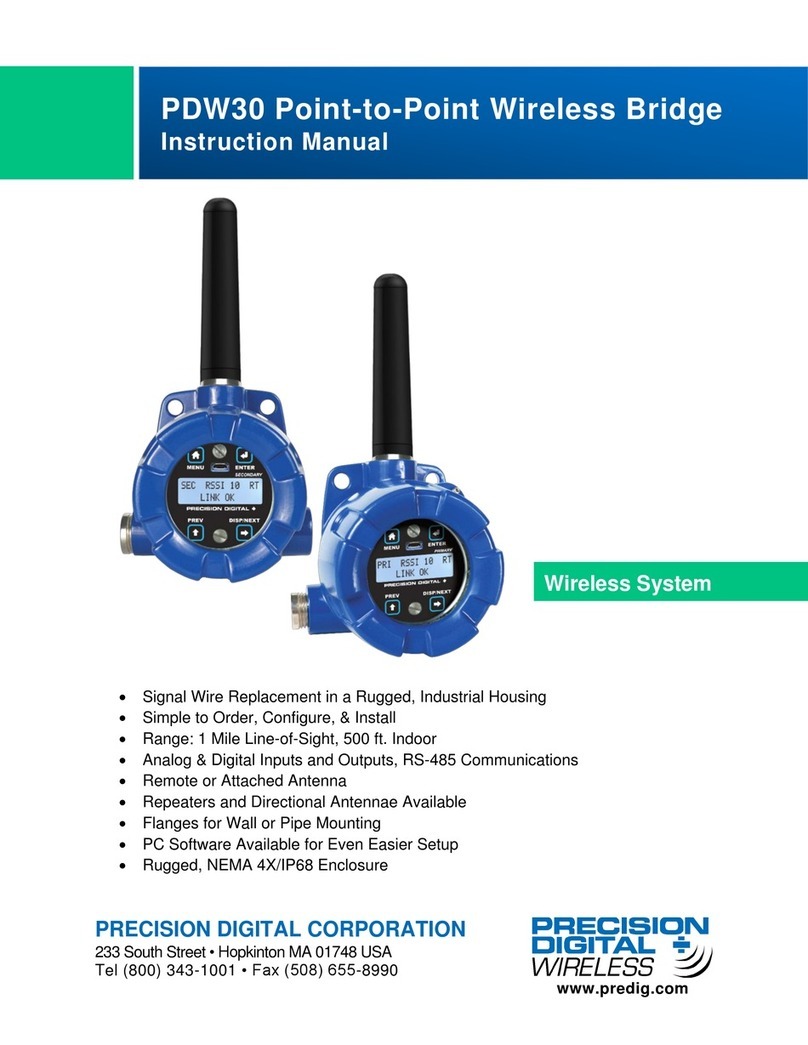
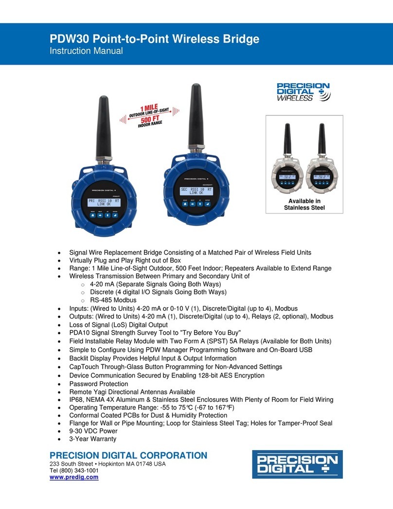
Precision Digital Corporation PDW30 User manual

www.predig.com
PRECISION DIGITAL CORPORATION
PDW30
Point-To-Point Wireless Bridge
FEATURES
• Signal Wire Replacement in a Rugged,
Industrial Housing
• Inputs and Outputs on Both Field Units
• Simple to Order, Configure, & Install
• 1 Mile Line-of-Sight Outdoor, 500 Feet
Indoor Range
• Inputs: Analog (4-20 mA, 0-10 V, 0-5 V, 1-5 V),
Digital, and RS-485 Modbus®
Communications
WIRELESS SYSTEM
WIRELESS
• Outputs: Analog (4-20 mA), Digital, and
RS-485 Modbus®Communications
• Remote or Attached Antenna
• Repeaters and Directional Antennas
Available
• Flanges for Wall or Pipe Mounting
• Software Available for Even Easier Setup
• NEMA 4X, IP68 Enclosure

www.predig.com
2
PDW30 Point-To-Point Wireless Bridge
IP68 Rated NEMA 4X
Aluminum Enclosure
KEY FEATURES
Signal Wire Replacement In a Rugged
Industrial Area
The PWD30 wireless system is housed in a rugged, IP68,
NEMA 4X painted aluminum enclosure and is a smart, economical
choice when you need two devices to communicate over long
distances in a harsh industrial environment. It eliminates the
need to spend time and money on hard wiring your instrumention
throughout your facility.
PDW30 Signal Range
The PDW30 has a range of 500 ft. indoors at industrial environments
and an outside line-of-sight range of 1 mile. Any wireless network can
be negatively aected by certain factors, such as physical obstacles
and improper equipment placement. Check the installation guide
and manual for tips on how to avoid common installation mistakes.
Flanges For Pipe
or Wall Mounting
32 character dual-
line alphanumeric
dot matrix LCD with
backlight. Displays
signal strength,
analog input & output
status, or digital IO
status
Four Programming
Buttons Behind Glass
Micro USB Connection
for Conecting Unit to
PC when using PDW
Manager Software
Stainless Steel
Conduit Plug
Label for Primary or
Secondary PDW30
Unit
Attached Antenna
(not fully pictured)
WIRELESS
INTRODUCTION
The Precision Digital PDW30 gives you a simple, straightforward
way to get an analog, discrete, or Modbus®signal from where you
have it to where you need it. It’s a point-to-point wireless bridge
packaged in a rugged, weather tight housing designed to meet the
demands of industrial installations.
The PDW30 is simple to order, simple to configure, and easy to
trust with your application. Guaranteed ranges assure it will work
with your application, or you can send it back - no questions asked.
A wireless survey tool is available for those who may require a site
survey for longer distances, making it easy to verify the installation
will work the first time.
The PDW30 starts with an analog, discrete, or Modbus®input and
wirelessly broadcasts it to a second PDW30 unit. The second unit
then recreates that signal at its location. Just put the units in the
field anywhere you have 12-24 VDC power.
Fixed or remote antenna modules are available, as well as a wide
range of accessories including mounting kits, antenna-related
accessories, and repeaters. The antenna may be directly attached
or remotely located. High gain directional antennas are also offered.
PDW30 Point-To-Point Wireless Bridge
Range: 500 Ft. (152.4 m) Indoor
1 mile (1.6 km) Outdoor Line-of-Sight

www.predig.com
3
PDW30 Point-To-Point Wireless Bridge
Input Signal Connector
The analog input may be either 4-20 mA, 0-10 V, 0-5 V, or 1-5 V.
The appropriate input type must be programmed for each unit.
4-20 mA Output Connector
The 4-20 mA output corresponds with the analog input signal on the
paired wireless device. The analog output signal is always 4-20 mA,
regardless of the analog input type on the other wireless module.
Inputs and Outputs
The PDW30 wireless bridge units accept an analog input (4-20 mA,
0-10 V, 0-5 V, or 1-5 V), up to four discrete digital inputs, and RS-
485 Modbus Communications. They also come with analog (4-20
mA), digital, and RS-485 Modbus outputs.
PDW Manager Software for Even Easier Setup
The PDW30 is designed to be easy to setup, with just a few button
pushes. However, the PDW Manager allows you to program the
PDW30 wireless units from a PC with a USB connection. Units
connect to a PC via the micro USB connection on their face,
underneath the enclosure cover. Use of PDW Manager is required
for programming advanced settings such as wireless encryption
and analog signal calibration. PDW Manager can be found on the
included CD or downloaded from www.predig.com/PDWManager.
Once the software is running, power the unit using a 12-28 VDC
power supply and connect the device to the PC using the provided
USB cable.
Modbus RTU Serial Communications
The PDW30 acts as a simple pass-through for Modbus
communications. As such, multiple Modbus enabled devices may
be transmitted wirelessly using the PDW30 Wireless Bridge.
D4 D3 D2 D1
GND
Digital I/O
Digital I/O Connector
All digital connections are referenced to ground. The primary unit
digital I/O settings determine the settings of the secondary unit.
(e.g. if DI of the primary is an input, DI of the secondary is an output)
Note: Each connection may be set independently in the device settings as
either an input or an output. In the diagram to the right, D4 & D3 are digital
inputs and D2 is a digital output.
mA
OUT-
mA
OUT+
AIN- AIN+
Signal
Voltage or
Current Signal
Source
+
-
▲ Signal Connector
mA
OUT-
mA
OUT+
AIN- AIN+
Signal
4-20 mA Input
Display, Chart
Recorder, Etc.
+
-
▲ 4-20 mA Output Connector
▲ Conguration Window of the PDW Manager Software
D4
D3
D2
D1 GND
Digital I/O
D-
D+ GND
Modbus
-+
Power
mA
OUT-
mA
OUT+
AIN- AIN+
Signal
Wireless
Module
CONNECTIONS
Wall or Pipe Mounting
The PDW30 has anges with two mounting holes that may be used
for a 1.5” pipe mounting or wall mounting. Alternatively, the unit may
be supported by the conduit using the conduit holes provided. It can
also be mounted by using a mounting bracket in orient the device
antenna away from the pipe. For best signal strength, do not mount
the module on metal pipe with the antenna parallel to the pipe.
NEMA 4X, IP68 Enclosure
The PDW30 units not only look great with their modern, smooth
die cast aluminum enclosures, but they can be installed virtually
anywhere. The NEMA 4X / IP68 rugged enclosure provides serious
protection from the elements and harsh industrial environments.
▲ Units connect to a PC via the micro USB connection
PRI RSSI 10 RT
LINK OK
12-28
VDC

www.predig.com
4
PDW30 Point-To-Point Wireless Bridge
N Connector
Fitting
Yagi Antenna
PDW30 Unit
PDA3120-N or
PDA3140-N
Extension Cable
YAGI HIGH GAIN ANTENNA ACCESSORY
The PDA3900 yagi antennas are made to work with point-to-
point applications. These high gain antennas are ideal to use with
Precision Digital’s PDW wireless series because they give you
the exibility of installing the antenna exactly where you need to
bridge your point-to-point wireless process signals while keeping
the PDW unit in a convenient location for monitoring. Each Yagi
is factory tuned on a network analyzer for best power match
and lowest VSWR, oering the best possible performance. The
PDA3900 also comes complete with a mounting kit with stainless
steel hardware.
Specifications
Frequency: 900 MHz
Gain: 6 or 9 dBd (based on model)
Termination: N-Female connector
Mounting Kit: Included for 1 ¼" pipe
Dimensions: PDA3900-6Y-N: 17.125" (435 mm) x 6.875" (175 mm),
PDA3900-9Y-N: 28" (711 mm) x 6.875" (175 mm)
Weight: PDA3900-6Y-N: 11.2 oz (318 g), PDA3900-9Y-N: 16.8 oz (476 g)
Mounting the Yagi Antenna
U-Bolt
Mast
Bracket
Yagi Antenna
Flat Washers
Locking Washers
Hex Nuts
Tighten to 6-8 ft/lbs
Connecting the Yagi Antenna to the PDW30 Unit
PDA3120-N or
PDA3140-N
Extension Cable
Cable Gland*
Antenna Coupler*
PDW30
Wireless Module
PDW30 Enclosure
and Cover
N Connector Fitting*
PDA3900 -9Y-N
PDA3 90 0- 6Y- N
*Included with the PDA3120-N or PDA3140-N Extension Cable Caution: Do not use accessive force when attaching coupler to PDW30 wireless module.
Coax Seal Tape*

www.predig.com
5
PDW30 Point-To-Point Wireless Bridge
SPECIFICATIONS
Except where noted all specifications apply to operation at +25°C.
General
Display: 32-character dual-line alphanumeric dot matrix LCD
display with backlight (4.68mm x 2.21mm characters)
Display Orientation: Display may be mounted at 180° from default
orientation.
Network ID: Field selectable: 0 - 99
Programming Methods: Four programming buttons (behind
glass) or PC with PDW Manager software.
Recalibration: All inputs and outputs are calibrated at the factory.
Recalibration is recommended at least every 12 months.
Process/Digital I/O Display: Press the display button once to
display the present analog input and output. Press the display
button again to display digital I/O states.
Password: A programmable password restricts modification of
program settings.
Power: 12-28 VDC, 5 W max
Non-Volatile Memory: All programmed settings are stored
in non-volatile memory for a minimum of ten years if power is lost.
Isolation: 500 V
Environmental: Operating temperature range: -40 to 65°C (display
inoperable < -20 °C); Storage temperature range: -40 to 85°C;
Relative humidity: 0 to 90% non-condensing
Connections: Removable screw terminal blocks accept 16 to 30
AWG wire.
Enclosure: Cast aluminum with glass window, 0.30% max copper
content, corrosion resistant powder coating, color: blue. NEMA
4X/IP68. Three ½” NPT threaded conduit openings. One ½” NPT
stainless steel conduit plug with 10 mm hex key tting installed.
Mounting: May be mounted directly to conduit. Two mounting
holes for 1.5” pipe or wall mounting. See manual for mounting
space requirements.
Signal Connector Tightening Torque: 2.5 lb-in (0.28 Nm)
Shipping Dimensions: 17” x 14” x 9” (43.2 cm x 35.6 cm x
22.9 cm) (L x W X H)
Shipping Weight: 5 lbs. (2.27 kg)
Warranty: 3 years parts & labor
Wireless Radio
Frequency: 900 MHz
Range: 500 ft (152.4 m) indoor,
1 mi (1.61 km) outdoor (line-of-sight)
Encryption: AES 128-bit encryption available using PDW Manager
software.
Interference Reduction: Frequency Hopping Spread Spectrum
(FHSS)
Power Output: 24 dBm (250 mW)
Sensitivity: -101 dBm
Antenna Cable Connection: RP-SMA right angle male
Analog Input
Inputs: Field selectable: 4-20 mA, 0-10 V, 0-5 V, 1-5 V
Accuracy: ±0.03% of calibrated span ±1 count
Temperature Drift: 0.005% of calibrated span/°C max from 0 to
65°C ambient, 0.01% of calibrated span/°C max from -40 to 0°C
ambient
Input Impedance: Voltage ranges: greater than 500 kΩ;
Current ranges: 50 - 100 Ω (depending on resettable fuse
impedance)
Signal Loss: Inputs will remain o (open circuit) until wireless
units are reconnected.
HART Transparency: Analog input will not interfere with existing
HART communications on the wired 4-20 mA signal
Isolated 4-20 mA Transmitter Output
Output Source: Analog input from connected wireless unit
Calibration: Factory calibrated: 4.000 to 20.000 = 4-20 mA output
Accuracy: ± 0.1% of span ± 0.004 mA
Temperature Drift: 0.4 μA/°C max from 0 to 65°C ambient,
0.8 μA/°C max from -40 to 0°C ambient
Note: Analog output drift is separate from input drift.
Signal Loss: mA output will become 3.2 mA after approx. 25
seconds.
Output Loop Resistance:
Power Supply Minimum Maximum
24 VDC 10 Ω 900 Ω
Digital Input / Output Terminal
Channels: Four (4) digital connections, independently eld
selectable as either inputs or outputs
DI Logic High: 3 to 5Vdc, TTL logic level
DI Logic Low: 0 to 1.1 VDC
DO Logic High: 3.1 to 3.3 VDC
DO Logic Low: 0 to 0.4 VDC
Source Current: 10 mA maximum output current
Sink Current: 1.5 mA minimum input current
Signal Loss: Digital output goes to logic high
Operation: A closed dry contact from a Digital input terminal to GND will
result in a digital output low on the corresponding output pin.
RS-485 Modbus®RTU Serial Communications
Compatibility: EIA-485
Connectors: Removable screw terminal connector
Max Distance: 3,937’ (1,200 m) max
Baud Rate: 1200 – 57,600 bps
Data: 8 bit (1 start bit, 2 stop bits)
Parity: Even, Odd, or None with 2 stop bits
Modbus Timeout: 0.5, 1, 2, 3, 4, 5 seconds; user selectable
PDW Manager Software
System Requirements: Microsoft®Windows®XP/Vista/7/8/10
Communications: USB 2.0 (Standard USB A to Micro USB B)
Configuration: Configure devices one at a time

PDW30 Point-To-Point Wireless Bridge
LDSW30_D 07/19
PRECISION DIGITAL CORPORATION
233 South Street • Hopkinton MA 01748 USA • Tel (800) 343-1001 • Fax (508) 655-8990
www.predig.com
Disclaimer
The information contained in this document is subject to change without notice. Precision Digital
Corporation makes no representations or warranties with respect to the contents hereof, and
specically disclaims any implied warranties of merchantability or tness for a particular purpose.
©2016-2019 Precision Digital Corporation. All rights reserved.
Your Local Distributor is:
ORDERING INFORMATION
PDW30 Point-to-Point Wireless System
Model Description
PDW30-SNA PDW30 Point-to-Point Wireless System
Accessories
Model Description
PDA30-RNA PDW30 Repeater Kit with Remote Antenna
PDA3900-12-N Remote PDW30 ½” NPT Antenna
PDA3900-6Y-N Remote 6 dB Yagi High-Gain Directional Antenna
PDA3900-9Y-N Remote 9 dB Yagi High-Gain Directional Antenna
PDA3120-S 20' RP-SMA M/F Antenna Extension Cable
PDA3140-S 40' RP-SMA M/F Antenna Extension Cable
PDA3120-N 20' RP-SMA F to N Male Extension Cable
PDA3140-N 40' RP-SMA F to N Male Extension Cable
PDA6963 Stainless Steel PDW30 Mounting Kit
PDA10 PDW Wireless Signal Strength Survey Tool
DIMENSIONS
Ø 0.35 (Ø 9.0)
2.31 (58.6)
4.30 (109.2)
4.27 (108.4)
2.44 (61.9)
2.74 (69.7)
3.62 (92.0)
2.17 (55.0)
½" NPT
5.50 (139.7)
Units: Inch (mm)
APPLICATION EXAMPLE
This simple example demonstrates how the PDW30 may be used
to wirelessly bridge an analog signal. Because the PDW30 can
input and output a 4-20 mA signal, it is ideal for integration into
existing 4-20 mA systems.
Note: Extension cables include the following parts:
(1) Antenna Coupler
(1) Cable Gland
(1) 8" Length of Coax Seal Tape
(1) ½" NPT Cable Gland
WARNING
Cancer and Reproductive Harm - www.P65Warnings.ca.gov
38.72
Feet
Analog Signal
(i.e. 4-20 mA, 0-10 V,
0-5 V, 1-5 V)
Sensor
Transmitter
Range: 500 ft (152.4 m) indoor, 1 mi (1.6 km) outdoor/line-of-sight
PDW30
Primary Unit
PDW30
Secondary Unit
4-20 mA
Destination Device
(e.g. display, PLC,
chart recorder, etc.)
Other manuals for PDW30
3
This manual suits for next models
1
Table of contents
Other Precision Digital Corporation Network Hardware manuals
Popular Network Hardware manuals by other brands

Wisenet
Wisenet PRN-3210B2 quick guide

evertz
evertz Topaz System manual

Westlock Controls Corporation
Westlock Controls Corporation Intellis 7604 Installation and operation manual
NDC
NDC 2.4GHz 802.11g Wireless Outdoor Bridge... Specifications
Alvarion
Alvarion BreezeACCESS VL System manual
Seenergy
Seenergy SVR-104 user manual
