EUROLAIKAS FS 1000 Mounting instructions
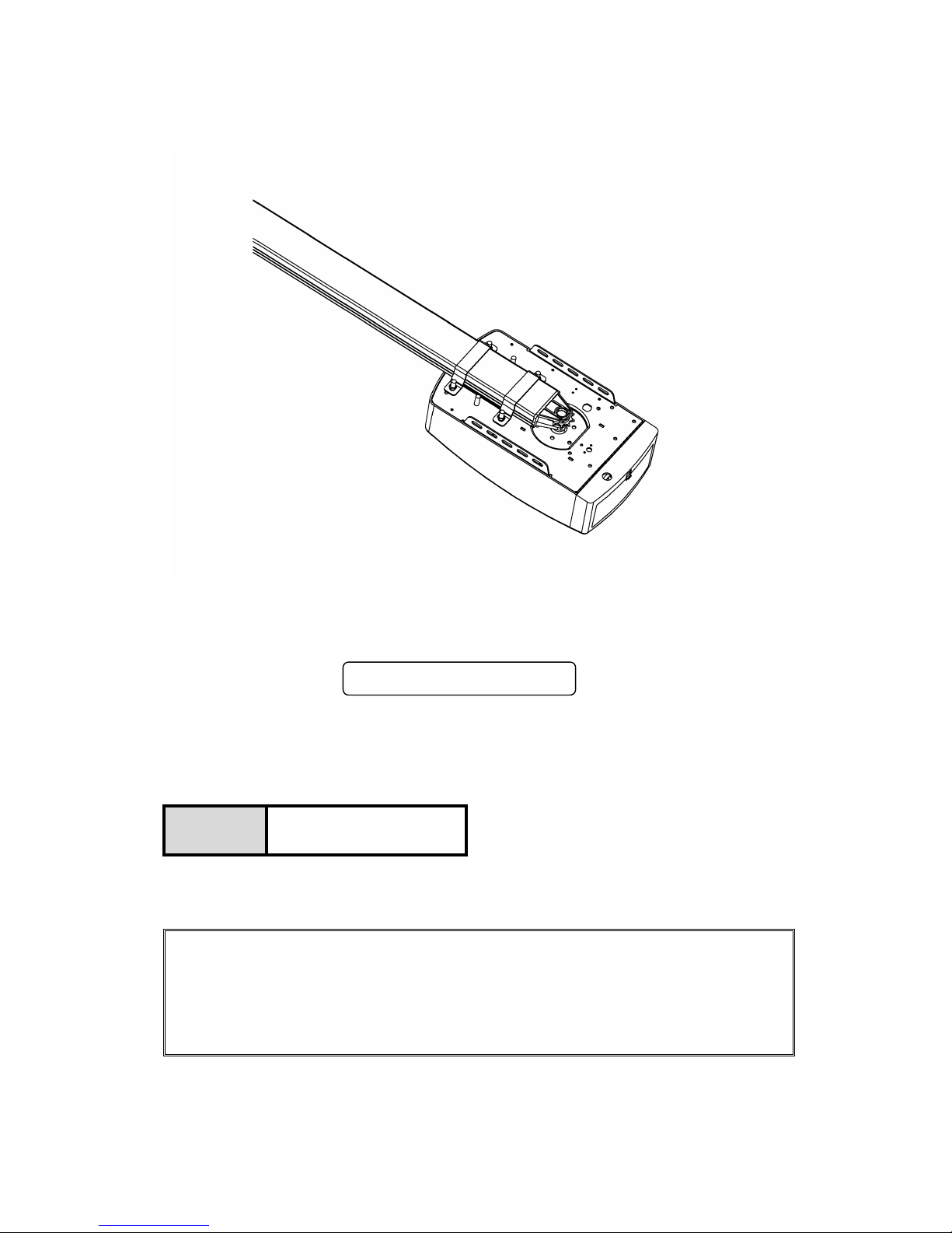
Sectional And Tilting Door Opener
Installation Instructions and User Guide
WARNING
S/N
Please read the manual carefully before installation and use.
The installation of your new door opener must be carried out by a technically qualified
or licensed person.
Attempting to install or repair the door opener without suitable technical qualification
may result in severe personal injury, death and / or property damage.
FS 1000 1000N

Important Safety Recommendations...…………………………….……………………………..1
Product Description & Features.............................................................................................2-3
Pre-Installation Recommendations ........................................................................................4
Installation (Wall Bracket & Door Bracket) .............................................................................4
Installation (Steel Track)……………………………………………………………………… .…...5
Installation (Sectional Steel Track Assembly)..........................................................................6
Battery Backup Assembly (optional)................................................................7
Display Menu Instructions
(Plus II)..........................................................................................................8
Programming Instructions....................................................................................................9-19
Terminal Introduction and Application.................................................................................20-21
Manual Disengagement..........................................................................................................22
Maintenance………………………………………………………….………………………..….….22
Technical Specifications………………………………………………………………………....23-24
Parts Listing………………………………….............................................................................25
Common Fault & Solutions ................................................................................................26-27
CONTENTS

1
FAILURE TO COMPLY WITH THE FOLLOWING SAFETY RECOMMENDATIONS MAY
RESULT IN SERIOUS PERSONAL INJURY, DEATH AND / OR PROPERTY DAMAGE.
1. PLEASE READ CAREFULLY AND ADHERE TO ALL SAFETY AND INSTALLATION
RECOMMENDATIONS.
2. The opener is designed and manufactured to meet local regulations. The installer must be
familiar with local regulations required in respect of the installation of the opener.
3. Unqualified personnel or those persons who do not know the occupational health and
safety standards being applicable to automatic gates and other doors, must in no
circumstances carry out installations or implement systems.
4. Persons who install or service the equipment without observing all the applicable safety
standards will be responsible for any damage, injury, cost, expense or claim whatsoever
any person suffered as a result of failure to install the system correctly and in accordance
with the relevant safety standards and installation manual whether directly or indirectly.
5. For additional safety we strongly recommend the inclusion of Photo Beam. Although the
opener incorporates a pressure sensitive Safety Obstruction Force system the addition of
Photo Beam will greatly enhance the operating safety of an automatic garage door and
provide additional peace of mind.
6. Make sure that the garage door is fully open & stationary before driving in or out of the
garage.
7. Make sure the garage door is fully closed & stationary before leaving.
8. Keep hands and loose clothing off the opener and garage door all the time.
9. The Safety Obstruction System is designed to work on STATIONARY objects only.
Serious personal injury, death and / or property damage may occur if the garage door
comes into contact with a moving object
10. This appliance is not intended for use by persons (including children) with reduced
physical, sensory or mental capabilities, or lack of experience and knowledge, unless they
have been given supervision or instruction concerning use of the appliance by a person
responsible for their safety. Children should be supervised to ensure that they do not play
with the appliance.
11. Waste electrical products should not be disposed of with household waste. Please
recycle where facilities exist. Check with your local authority or retailer for recycling
advice.
12. If the supply cord is damaged, it must be replaced by the manufacturer, its service agent
or similarly qualified persons in order to avoid a hazard.
- WARNING: Important safety instructions. It is important for the safety of persons to follow
all instructions. Save these instructions.
- Do not allow children to play with door controls. Keep remote controls away from children.
- Watch the moving door and keep people away until the door is completely opened or
closed.
- Take care when operating the manual release since an open door may fall rapidly due to
weak or broken springs, or being out of balance.
- Frequently examine the installation, in particular check cables, springs and mountings for
signs of wear, damage or imbalance. Do not use if repair or adjustment is needed since a
fault in the installation or an incorrectly balanced door may cause injury.
- Each month check that the drive reverses when the door contacts a 50 mm high object
placed on the floor. Adjust if necessary and recheck since an incorrect adjustment may
present a hazard, for drives incorporating an entrapment protection system depending on
contact with the bottom edge of the door.
- Details on how to use the manual release.
- Information concerning the adjustment of the door and drive.
- Disconnect the supply when cleaning or carrying out other maintenance.
- The installation instructions shall include details for the installation of the drive and its
associated components.
IMPORTANT SAFETY RECOMMENDATIONS

2
1. Obstruction force adjustment
The minimum force display “1”and it can be adjusted upward. Display “5”means the
maximum force.
2. Travel speed adjustment
“8”appears on the display means the 80% of the travel speed. Display“A”means the
full speed 160mm/s or 200mm/s.
3. Reversal height adjustment
“0”appears on the display means the door will rebound to the top. Display “1~9”
means the door will rebound to the position of the whole travel. One tenth to Nine tenth of the
whole travel etc.
4. Partial open/height
“0”appears on the display means close the partial open function. Display“1~9”means
to set the different partial open position of the whole travel.
5. Transmitter button recognition function
“0”appears on the display means the buttons recognition function is closed. Display“1”
means the buttons recognition function is open.
6. Codes memory quantity
“A”appears on the display means the maximal code memory quantity is 50pcs. Press
UP/DOWN button once, to increase or decrease quantity. The code memory quantity is set on
5pcs*N, N=1~9. (The quantity is the multiple of 5).
7. Maintenance alarm
“b”appears on the display and led light flashes 10 times quickly means the garage door
and motor need total maintenance.
8. Automatic safety reverse
Automatic stop / automatic reverse are controlled by our software of circuit boards. We
are circumspect to protect your children, pet or other goods.
9. Soft start / Soft stop
Ramping speed up and down at the start and end of each cycle reduces stress on the
door and opener for longer life, and makes for quieter operations.
10. Auto-Close
Auto- Close ensures peace of mind and keeps your house secure by automatically closing
the door upon entering or exiting the garage.
11. Self learning open and close obstruction force
The amount of opener power for different stages of the door’s travel is learnt during setup
and is constantly re-profiled. Opener force measurement automatically adjustment in a
suitable range.
12. Electronic limit, simple adjustment.
You only need control the limit setup from control panels to adjust it exactly, the simple
and quick process for any peoples.
13. Available terminal for Photo beams & Extra receivers & Wire or wireless wall switch
& Caution light & Pass door protection device.
14. Energy saving - L.E.D courtesy light
3 minutes L.E.D light delay, switching on with each cycle to illuminate your darkened
garage.
PRODUCT DESCRIPTION & FEATURES

3
15. Battery backup available
Openers could be supplied power with our battery backup once the power failure at your
home.
16. Self-Lock in gear motors
Gear motor will self-lock with its disengagement systems.
17. Manual release
Don't worry about the power failure, the manual release system is a solution for operation
the door at any time.
18. Transmitter technology
Rolling Code technology (7.38 x 10¹⁹ Combinations), 433.92 MHz frequency, 4 channels
design to ensure you can control 4 different doors with one transmitter.
19. Applications
With as little as 30mm required between the ceiling and the highest point of the door travel,
the opener can be flush mounted for low headroom applications.
20. Metal bottom plate, stronger and security.
21. Up / Down moving operation buttons (UP / DOWN)
Close
Open

4
1. Garage door must be able to be lifted and closed easily by hand and without much effort. A
well balanced & sprung door is critical for proper installation.
2. The garage door opener can’t compensate for a badly installed garage door and should
not be used as a solution for a “hard to open” door.
3. If the unit is being installed on an existing door, make sure any existing locking devices are
removed or warranty will be void.
4. An approved outlet must be installed near where the opener is begin installed.
5. There should be a minimum gap of 30mm between the bottom of the chain drive rail and
the top of the garage door at its closest point. (refer to Fig 1.)
Important note: As for additional safety rules, we strongly recommends the fitting of Photo
Electric safety beams on all installations.
Figure 1
Mount Wall Bracket and Door Bracket (Fig2)
Wall Bracket - Close the garage door and measure the
garage door width at the top and mark the centre. Locate and
mount the wall bracket 2cm-15cm above the door on the
inside wall.
(Depend on the actual installation space).
Door Bracket –Fix the door bracket to a structural part of the
door as close to the top edge as possible.
Figure 2
PRE-INSTALLATION RECOMMENDATIONS
INSTALLATION INSTRUCTIONS
5
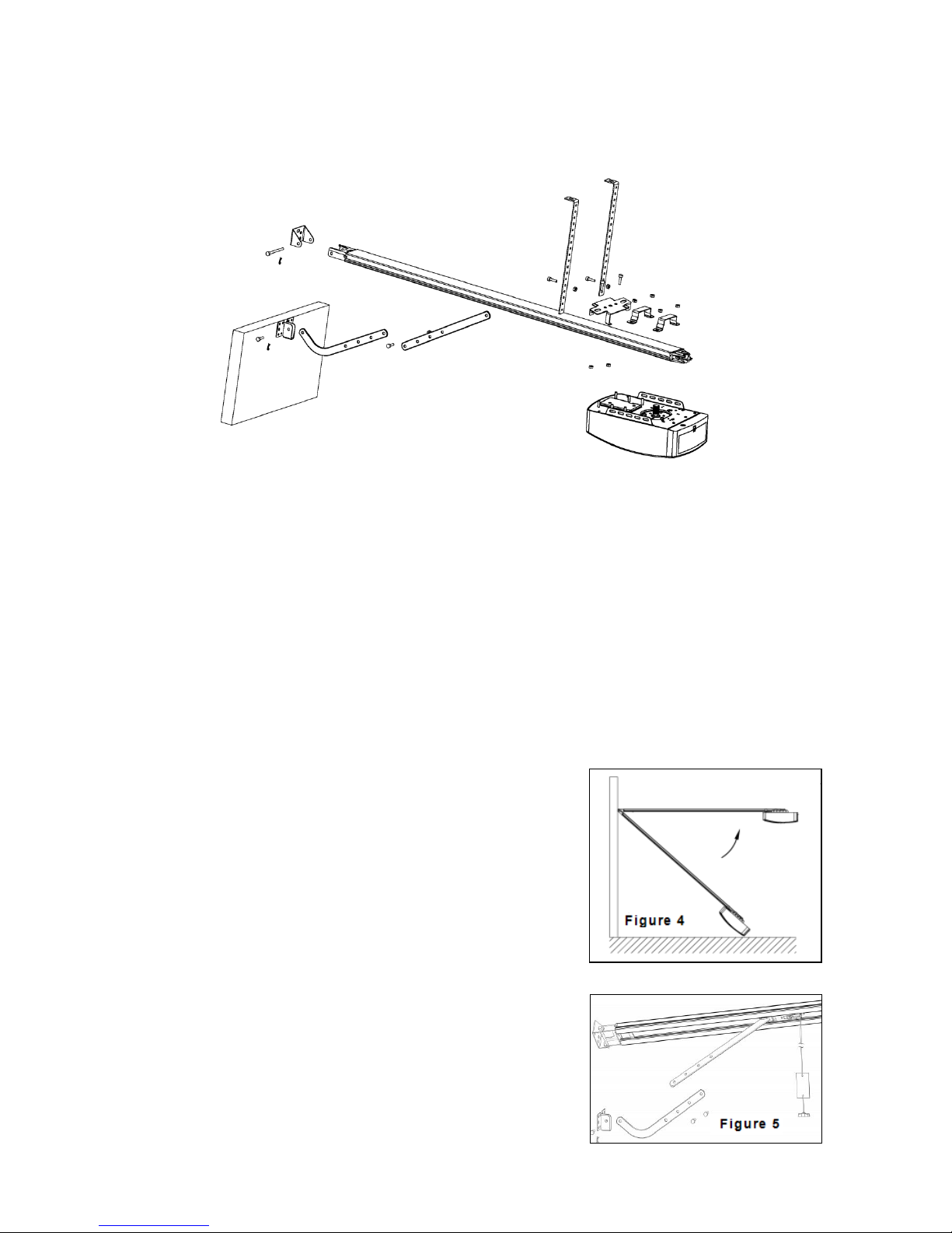
Installation (Steel Track)
STEP1 (Fig.3)
Attach the opener head to the steel track. Assembly the 2 “U” Hanging brack ets
with 6mm nuts supplied.
STEP2 (Fig.3)
Place the steel track and opener head assembly centrally on the garage floor, with
the open head furthest away from the door. Lift the front of the track up to the door
bracket. Insert the pivot pin and secure it with the split pin supplied.
STEP3 (Fig.3, Fig.4)
Lift and support the opener head (with a ladder) so it is
positioned centrally and level. Fix the opener and track
on ceiling by Iron bracket A & B.
WARNING: Do not allow children around the door,
opener or supporting ladder serious injury and/or
damage may result from failure to follow this warning.
STEP4 (Fig.3, Fig.5)
Connect the straight arm to the bent arm with the bolt.
Position and bolt the arms to the top edge of the door using
the bolt supplied.
STEP5
Lift the garage door until the shuttle locks into the
drive chain/belt.
Now, ready to program the openers.
Figure 3

6
Sectional Steel Track Assembly
1. 2-Parts Track:
As Fig.6, slide the Arail into the sleeve, slide the B rail into the sleeve.
3-Parts Track:
As Fig.7, slide the C rail into the sleeve, slide the D rail into the sleeve; slide the E rail into
the sleeve.
2. Cut the plastic thread; pull the screw rod along with inner chain to the end rail position
(Fig.8)
3. As Fig.9, release the nut & spring.
4. Tight the nut to the right position as shown in Fig.10, cut the plastic tape, cut the plastic
thread on sprocket, then whole rail assembled finished.
3 Parts Steel Track
2 Parts Steel Track
F
F
A:1500 mm
B:1500 mm
Sleeve
C:1000 mm
Sleeve
Sleeve
D:1000 mm
E:1000 mm

7
Battery backup Assembly (optional)
Option 1 - Top Fixed
STEP1 (Fig.11)
Assemble the battery & battery bracket like the photo, fix by screws supplied.
STEP2 (Fig.12)
Join the battery to opener, find the Fig.12.
Figure 11 Figure 12
Option 2 - Side Fixed
STEP1 (Fig.13)
Assemble the battery & battery bracket like the photo, fix by screws supplied.
STEP2 (Fig.14)
Join the battery to opener, find the Fig.14.
Figure 13 Figure 14
8
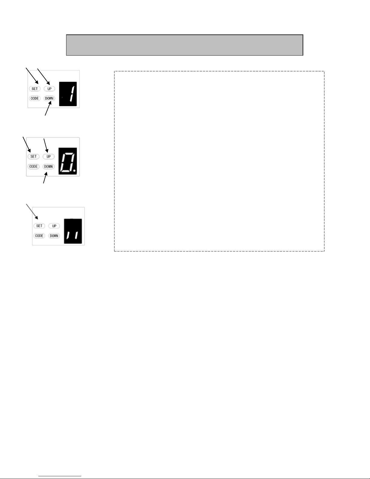
FEATURES SETTINGS:
a)Press and hold SET button until “1” appears on the display then release
the button.
b)Press UP / Down button, then it displays the number “1-E”.
c)Press Set button to confirm the feature you need to set, then it enters to
the interface for detail setting of the appointed feature.
d)In the detail setting interface display “0-A” with flash dot.
e)Press UP / Down button to choose the feature you need to set.
f )Press SET button to confirm the set and it will back to standby status
automatically and display “ll”.
DISPLAY MENU INSTRUCTIONS

9
Pre- Instruction for programme buttons
1. Short click SET button : When it standby, it will clear the error, alarm display, and
return to normal display.
2. Short click CODE button :
( In the Setting Status) Exit the current operation and return to the standby
interface.
When it standby, press the code, A dot will be indicated in the corner, now
entering the code leaning mode.
Now first click the button on the hand transmitter you want to use, the dot may
disappear ,then press again the same button on the hand transmitter, the dot will flash,
here, the code learning is finished.
3. Short press UP button : The door will open.
4. Short press DOWN button : The door will close.
(When the door is opening or closing, it will stop if you press any key.)
5. Long press SET button : Enter function setting interface.
6. Long press CODE button : Press and hold CODE button until a C is indicated on the
display. All stored remotes will be deleted.
7. Long press UP button : Increase the resilience. (Keep press DOWN button, after 4
seconds, it will scroll to display 0-1-2, choose the number you want. 1=increase 25%
2=increase 50%)
8. Long press DOWN button : Restore Factory Settings
Keep press DOWN button, after 4 seconds, it will scroll to display , then the
garage door opener will restart.
Restart means all settings are back to factory settings, all learning things need to be done
again except the transmitter code learning.
PROGRAMMING INSTRUCTIONS

10
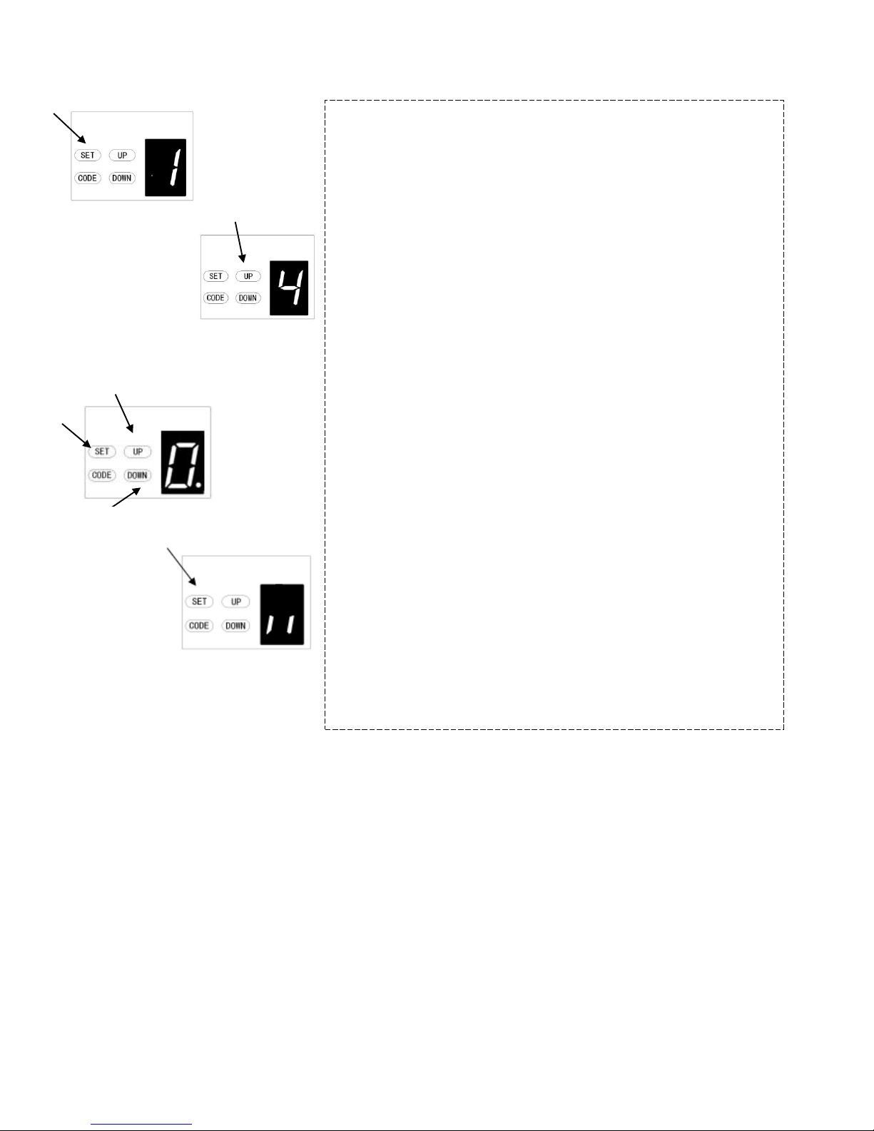
1. PROGRAMMING OPEN & CLOSE LIMITS
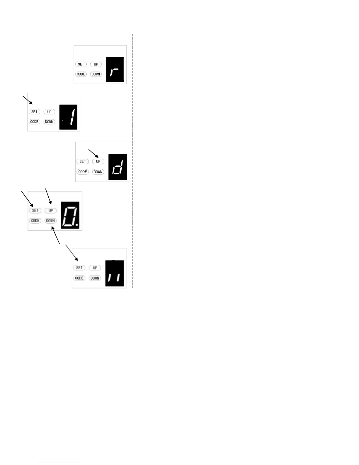
a) Press and hold SET button to enter this function setting
until “1” appears on the display then release the button.
b) Press the SET button again. The door opener is now in
Programming Mode. And then you will see “n” with dot
appears on the display.
c) Press and hold the UP button until the door reaches the
desired open position, you will see “n” without dot on the
display.
d) Press SET button to confirm the open position, then you
will see “u” with dot on the display.
e) Next press and hold the DOWN button until the door
reaches the desired close position, you will see “u” without
dot on the display.
NOTE: For fine adjustments toggle UP & DOWN
buttons.
f) Now press the SET button to confirm the close position,
then you will see “II” on the display.
After confirm the close position, the door will now cycle open
and close to set the travel limits and force sensitivity
adjustments. The door is now set for normal operation.
CAUTION: After the cycle open and close, there will be
figures shown on the display (0~9), “0”means the doors is
balanced, the smaller figure means the better door balance,
strongly recommend that the figure need to be smaller than
the power force.
PROGRAMMING INSTRUCTIONS

11
2. OBSTRUCTION FORCE ADJUSTMENT
CAUTION: The obstruction force adjustment is set automatically
during programming. Normally no adjustment is necessary.
a) Press and hold SET Button until “1”appears on the display, next
press the UP Button until “2”appears on the display to enter this
function setting then release the button.
b) Press the SET button again, The unit is now in force adjustment
mode. And then you will see a figure “3”with flash dot appears on the
display.
c) Press the UP button to increase the force setting or the DOWN
button to decrease the force setting.
The minimum force is “1”and it can be adjusted upward. The
maximum force is “5”.
d) Press SET button to confirm the set and it will back to standby
status automatically and display “ll”.
NOTE: The force is set on “3”as standard in factory.
3. TRAVEL SPEED SETTING
CAUTION: If you changed the speed again, it will cancel the
previous travel limit. The speed adjustment function will be
available only after you reset the travel limit.
a) Press and hold SET Button until “1”appears on the display, next
press the UP button until “3” appears on the display to enter this function
setting then release the button.
b) Press the SET button again. The unit is now in speed adjustment
mode. And then you will see a letter “A”with flash dot appears on the
display.
c) Press the UP & DOWN button to choose the speed. Figure “8”
means the 80% of the travel speed. Figure “A” means the full speed.
d) Press SET button to confirm the set and it will back to standby
status automatically and display “ll”.
NOTE: The travel speed is set on full speed “A” as standard in factory.
Increase force
Decrease speed
Decrease force
Increase speed
12
4. AUTOMATIC CLOSING&TIME SETTING
NOTE: We recommend that Safety Photo Beams be used in any
installation where the Auto Close function is enabled.
a) Press and hold SET Button until“1”appears on the display, next
press the UP button until “4”appears on the display to enter this function
setting then release the button.
b) Press the SET button again, the unit is now in automatic close
adjustment mode. And then you will see a figure “0”with flash dot
appears on the display.
c) Press UP / Down button once to set the auto close time (0~9).
d) Press UP button to increase the time, or DOWN button to decrease
the time.
The close time is 15second*N, N=0~9. The maximum time is 135s. To
disable Auto Close Function, set time to zero (0).
e) Press SET button to confirm the set and it will back to standby
status automatically and display “ll”.
NOTE: 1.The closing time is set on “0”as standard in factory.
2. If the Photo Cell Function is on, and it’s broke by the
obstruction, the auto close time will stop for a while, and then continue the
automatic close time again.
Increase time
Decrease time

13
5. AUTOMATIC CLOSING CONDITION SETTING
a) Press and hold SET Button until “1”appears on the display, next
press the UP button until “5”appears on the display to enter this
function setting then release the button.
b) Press the SET button again. The unit is now in automatic close
condition adjustment mode. And then you will see a figure “1”with flash
dot appears on the display.
c) Press UP / Down button once to set the auto close condition. You
can choose “1”or “2”set.
Figure “1”means, the door only can auto close while in the open
limit position.
Figure “2”means, the door can auto close while the door is in any
position.
d) Press SET button to confirm the set and it will back to standby
status automatically and display “ll”.
NOTE: 1. The closing condition is set on “1” as standard in factory.
2. The door will only automatic close while in its opening process,
but can’t automatic close after it is stopped while in its closing process.
6. LED OFF DELAY TIME SETTING
a) Press and hold SET Button until “1”appears on the display, next
press the UP button until “6”appears on the display to enter this
function setting then release the button.
b) Press the SET button again. The unit is now in LED off delay time
adjustment mode. And then you will see a figure“3”with flash dot appears
on the display.
c) Press UP / Down button once to set the LED off delay time (1~9).
d) Press UP button to increase the time, or DOWN button to
decrease the time.
The delay time is 1 minute*N, N=1~9. The maximum delay time is 9
minutes.
e) Press SET button to confirm the set and it will back to standby
status automatically and display “ll”.
NOTE: The LED off delay time is set on “3”as standard in factory.
Decrease
Increase
Decrease time
Increase time

14
7. REVERSAL HEIGHT SETTING
a) Press and hold SET Button until “1”appears on the display, next
press the UP button until “7”appears on the display to enter this function
setting then release the button.
b) Press the SET button again. The unit is now in reversal height
adjustment mode. And then you will see a figure “0”with flash dot appears
on the display.
c) Press UP / Down button once to set the reversal height while closing
(0~9).
d) Press UP button to increase , or DOWN button to decrease.
Figure “0”means the door will rebound to the open limit position.
Figure “1~9”means the door will rebound to the position of the whole
travel. One tenth to Nine tenth of the whole travel etc...
e) Press SET button to confirm the set and it will back to standby status
automatically and display “ll”.
NOTE: The reversal height is set on “0”as standard in factory.
Decrease height
Increase height

15
8. PARTIAL OPEN/HEIGHT SETTING
a) Press and hold SET Button until “1”appears on the display, next
press the UP button until “8”appears on the display to enter this
function setting then release the button.
b) Press the SET button again. The unit is now in partial-open/height
adjustment mode. And then you will see a figure “0”with flash dot
appears on the display.
c) Press UP / Down button once to select if you want to open the
partial open function or set the partial open height. (0~9). Press UP
button to increase , or DOWN button to decrease.
Figure “0”means close the partial open function.
Figure “1~9”means set the partial open position of the whole travel.
One tenth to Nine tenth of the whole travel etc...
d) Press SET button to confirm the set and it will back to standby
status automatically and display “ll”.
Increase
Decrease

16
A. CODES MEMORY QUANTITY SETTING
a) Press and hold SET Button until “1”appears on the display, next
press the UP button until “A”appears on the display to enter this function
setting then release the button.
b) Press the SET button again, the unit is now in remote quantity
adjustment mode. And then you will see a figure “A” again, but with flash dot
appears on the display.
c) Press UP / Down button once to set the remote quantity. (A or 1~9).
d) Figure “A”means the maximal quantity 50pcs. Press UP/DOWN
button once to increase or decrease quantity.
The remote quantity is set on 5pcs*N, N=1~9. (The quantity is the
multiple of 5)
e) Press SET button to confirm the set and it will back to standby status
automatically and display “ll”.
NOTE: The remote quantity is set on “A”as standard in factory.
9. TRANSMITTER BUTTONS RECOGNITION FUNCTION SETTING
a) Press and hold SET button to enter this function setting until “9”
appears on the display then release the button.
b) Press the SET button again. The unit is now in buttons recognition
function adjustment mode. And then you will see a figure “1” with flash dot
appears on the display.
c) Press UP / Down button once to select if you want all the 4 buttons
can control the only one opener, or only the separate coded button can
control the opener.
Figure “0”means the buttons recognition function is closed. It means
if you coded 1 button with 1 opener, then all the 4 buttons on the
remote can control the opener. It’s suit for the users who only have 1
automation door at home.
Figure “1”means the buttons recognition function is open. If you
coded first button with first opener, then the first button will be the only
button on the remote can control the opener. It’s suit for the users who
have more than 1 automation doors/gates at home.
d) Press SET button to confirm the set and it will back to standby status
automatically and display “ll”.
NOTE: 1. The buttons recognition is set on “1” as standard in factory.
2. After you changed the buttons un-recognition into recognition,
please notice that only the coded button can control the opener.
Decrease quantity
Increase quantity
Buttons recognition function is open
Buttons recognition function is closed

17
C. PASS DOOR SWITCH TYPE SETTING
a) Press and hold SET Button until “1”appears on the display, next
press the UP button until “C”appears on the display to enter this function
setting then release the button.
b) Press the SET button again. The unit is now in the pass door switch
type adjustment mode. And then you will see a figure “0”with flash dot
appears on the display.
c) Press UP / Down button once to set the pass door switch type. You
can choose “0”or “1”set.
Figure “0”means, the pass door function is normally open.
Figure “1”means, the pass door function is normally close.
e) Press SET button to confirm the set and it will back to standby
status automatically and display “ll”.
b. REVERSAL HEIGHT IGNORANCE SETTING
a) Press and hold SET Button until “1”appears on the display, next
press the UP button until “b”appears on the display to enter this function
setting then release the button.
b) Press the SET button again. The unit is now in reversal height
ignorance adjustment mode. And then you will see a figure “1”with flash
dot appears on the display.
c) Press UP / Down button once to set the reversal height ignorance
while closing (0~9).
d) Press UP button to increase , or DOWN button to decrease.
Figure “1~9”means the door will still not rebound even though
there’s obstacles in its closing path within 1cm~9cm away from the
close position. This function is most suitable for the Northern
Europe where will always snow on the ground.
e) Press SET button to confirm the set and it will back to standby
status automatically and display “ll”.
NOTE: The reversal height is set on “1”as standard in factory.
Decrease height
Increase height
18
d. PHOTO CELL ON/OFF SETTING
NOTE: Make sure the photo cell has been correctly installed and used
Normally Closed contacts to the accessory terminals of the opener.
Also note that the photo beam function must be disabled if NO photo
beams are fitted, otherwise the door cannot be closed, and the LED
display will show the letter“r ”as an indication.
a) Press and hold SET Button until “1”appears on the display, next
press the UP button until “d”appears on the display to enter this function
setting then release the button.
b) Press the SET button again. The unit is now in the photo cell ON/OFF
adjustment mode. And then you will see a figure “0”with flash dot appears
on the display.
c) Press UP / Down button once to set the photo cell ON/OFF switch.
You can choose “0”or “1”set.
Figure “0”means, the photo cell function is closed.
Figure “1”means, the photo cell function is open.
d) Press SET button to confirm the set and it will be back to standby
status automatically and display “ll”.
NOTE: The photo cell is set on “0”as standard in factory.
This manual suits for next models
1
Table of contents
Popular Door Opening System manuals by other brands

Raynor
Raynor ControlHoist CMT Installation instructions manual

Dictator
Dictator DICTAMAT 50 BK-Z Technical manual

Assa Abloy
Assa Abloy 281 Series installation instructions

Johnson Controls
Johnson Controls MC-303 PG+ Nstallation guide

Assa Abloy
Assa Abloy SARGENT 3828 Series instructions

Assa Abloy
Assa Abloy Sargent 2409 Series Wiring instructions


