Eco SR-EF BG User manual
1100 mm +7
1250 mm +15
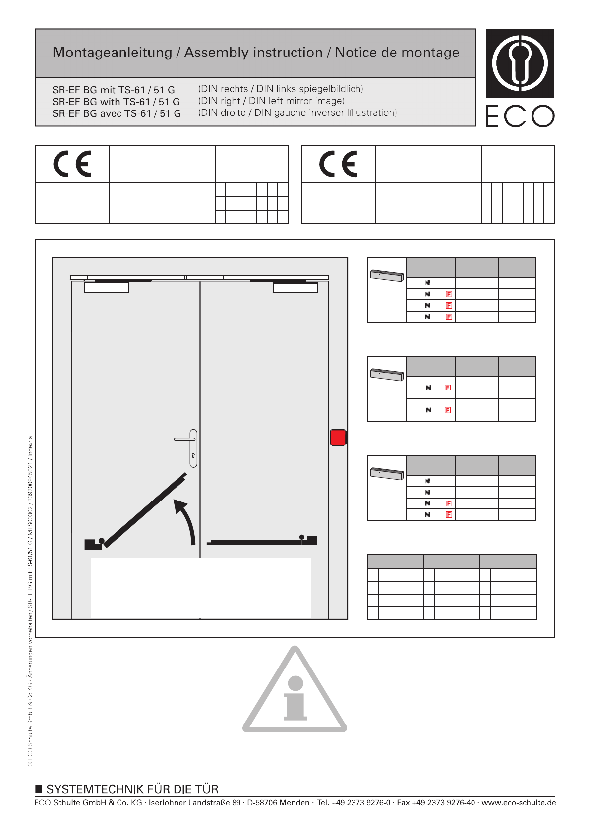
TS-61 G
EN 2-5
2850 mm -5
950 mm 0
Türschließergröße
Door closer size
Force de ferme porte
Max. Türbreite
Max. door width
Largeur de porte max.
Umdrehungen
Rotations
Rotations
3
4
5
Türschließergröße
Door closer size
Force de ferme porte
Max. Türbreite
Max. door width
Largeur de porte max.
Umdrehungen
Rotations
Rotations
TS-61 G
EN 5-6 6
5
1400 mm
1250 mm
+6
0
950 mm 0
1100 mm +6
1750 mm -7
850 mm -4
Türschließergröße
Door closer size
Force de ferme porte
Max. Türbreite
Max. door width
Largeur de porte max.
Umdrehungen
Rotations
Rotations
2
3
4
TS-51 G
EN 1-4
1/17
Abkürzungen
Schließ-
geschwindigkeit
SG
ES
ÖD
SK
Endschlag
Öffnungs-
dämpfung
Schließkraft
CS
Abbrevations Abrévations
Closing speed
LS
BC
CF
Latching speed
Back check
Closing force
Vitesse de
fermeture
VF
CF
FO
FF
Coup final
Frein á
l’ouverture
Force de
fermeture
GS
DIN links - spiegelbildlich
DIN left - mirror image
DIN gauche - inverser l´illustration
Tür
schließen
Leistungserklärung nach Verordnung (EU) Nr. 305/2011 finden Sie unter http://www.eco-schulte.de/leistungserklaerungen
Declaration of performance according to Regulation (EU) No 305/2011 see http://www.eco-schulte.de/declarationofperformance
Déclaration des performances conformément au règlement (UE) N° 305/2011 voir http://www.eco-schulte.de/declarationdesperformances
Only original parts have to be used. The assembly has to be made by a qualified person according to the mounting instruction. In case of
non-respect the guarantee is invalid. This instruction is to be handed over to the operator by the fitter after assembly!
Impérativement utiliser la notice de montage fournie par le fabricant. La mise en œuvre et le montage doivent être exécutés par du person-
nel qualifié. Le non respect de ces règles annule catégoriquement tout droit de garantie Cette instruction est à remettre par le poseur
à l’exploitant après montage.
Für die Montage dürfen ausschließlich Originalteile des Herstellers verwendet werden. Die Montagearbeiten müssen gemäß Anleitung von
einer qualifizierten Person durchgeführt werden. Bei Nichtbeachtung entfällt jeglicher Garantieanspruch. Diese Anleitung ist vom Monteur
nach der Montage an den Betreiber weiterzugeben!
ECO Schulte GmbH & Co. KG
Iserlohner Landstraße 89
D-58706 Menden
0432 - CPD - 0031 EN 1154:1996+A1:2002 2-5 41 1
5-6 41 1
3
3
3
8
8
8 1-4 31 1
06
ECO Schulte GmbH & Co. KG
Iserlohner Landstraße 89
D-58706 Menden
3-5 01 13 8
06
0432 - CPD - 0147 EN 1158:1997+A1:2002
0432 - CPD - 0143 EN 1155:1997+A1:2002

2/17
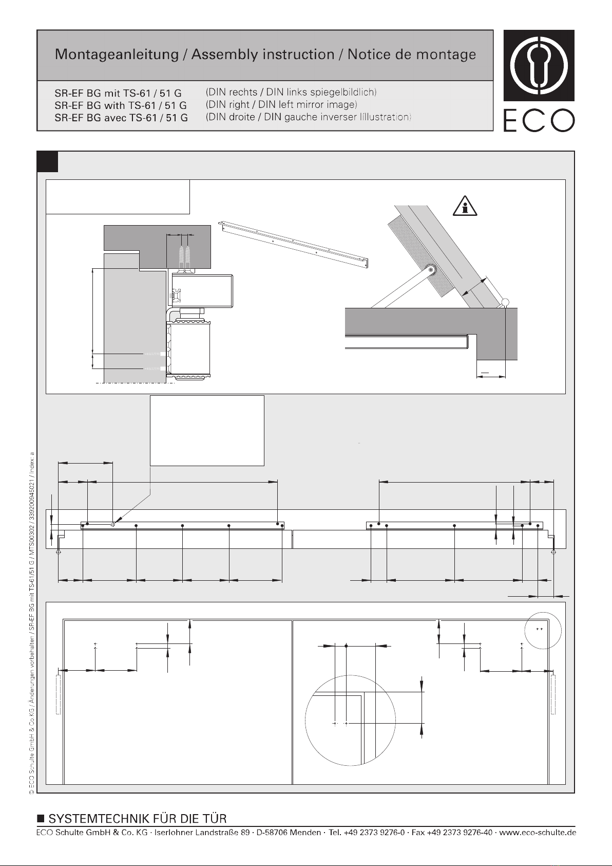
1a
122
53
A
160
16
122
160
16
53
120 546
13
446
60,5
59,5
13
X
X = 55-92mm
Direktmontage (ohne Unterprofil)
Direct mounting (without underprofile)
Montage direct (sans sous profil)
GS
18 46
22,5
A
27
23
Ø12
16 13
53
258
Bohrung für elektrischen
Anschluss (24 V DC)
Drilling for electrical
connection (24 V DC)
Alésage pour raccordement
électrique (24 V DC)

1b
3/17
122
53
A
160
16
122
160
16
53
546
26
446
60,5
120 59,5
26
X
X = 55-92mm
GS
Montage mit Adaptionsprofil
Mounting with adaptor plate
Montage avec profil d’adaptation (optional, optional, optionnelle)
18 46
22,5
A
Ø 12
37
130
16 26
53
258
Bohrung für elektrischen
Anschluss (24 V DC)
Drilling for electrical
connection (24 V DC)
Alésage pour raccordement
électrique (24 V DC)
1c
4/17
X = 60-92mm
122
95
A
160
16
122
160
16
95
18 46
64,5
A
94,5
77 205
205 146 146
667 582 90,5
60
261
261
60
60,5
17
24
Montage mit Sturzfutterwinkel
Mounting with under-lintle angle
Montage sous linteau avec équerre
X
33
<
(optional, optional, optionnelle)
GS
Ø12
20
180
16 95
717
Bohrung für elektrischen
Anschluss (24 V DC)
Drilling for electrical
connection (24 V DC)
Alésage pour raccordement
électrique (24 V DC)

5/17
3a
2
2
1
3
4
2
2
1
1
Other Eco Door Opening System manuals


 User manual")

Popular Door Opening System manuals by other brands


Besam
Besam Swingmaster MP Installation, adjustment and maintenance instructions

Assa Abloy
Assa Abloy SARGENT 1431 Series instructions

GAL
GAL MOVFR Quick setup

Häfele
Häfele Finetta T 70 VF manual

AGS
AGS D-PL Instructions for fitting, operating and maintenance

Stanley
Stanley MA900ñ Installation and owner's manual

WITTUR
WITTUR Hydra Plus UD300 Instruction handbook

Alutech
Alutech TR-3019-230E-ICU Assembly and operation manual

Pamex
Pamex KT-INP35 Installation instruction

MPC
MPC ATD ACTUATOR 50 ATD-313186 Operating and OPERATING AND INSTALLATION Manual

Chamberlain
Chamberlain T user guide

Dorma
Dorma MUTO COMFORT M DORMOTION 50 Mounting instruction