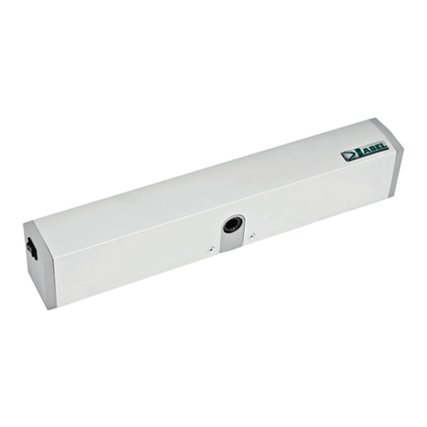
Label NEPTIS/LE User manual

Installation
Manual
SWING DOOR
OPERATOR
for one or two wings GB
Nepti
Nepti
S
CD0356GB - NEPTIS/LE - Rel.1.0 - 03/2007
NEPTIS/LE

Manufacturer: LabelS.p.A.
Address: viaIlariuzzi17/A-43100SanPancrazioParmese.PARMA-ITALY
Declaresthat: theNEPTIS/LE actuatorforswingdoors
8has been designed to be built into machinery or to be assembled with other devices so as to form
machinerycoveredbyMachine
6Directive 98/37/EC and that it conforms to the essential safety requirements of the following
directives:
!LowVoltageDirective73/23/EECandsuccessivemodification93/68/EEC
!Electromagnetic compatibility Directive 89/336/EEC and successive modifications 92/31/EEC
and93/68/EEC
LABEL S.p.A.
Sede: ITALY - 43100 PARMA - S. Pancrazio P.se - Via Ilariuzzi, 17/A
Tel. (+39) 0521/6752 - Fax (+39) 0521/675222
Parma, 15/06/2006
The President
Bruno Baron Toaldo
DECLARATION OF CONFORMITY

MECHANICAL SECTION page 4
1.0 ACTUATOR COMPONENTS “ 5
2.0 ARMS “ 5
3.0 GENERAL SAFETY RECOMMENDATIONS “ 6
4.0 MACHINE DIRECTIVES “ 6
5.0 INSTRUCTIONS FOR USE “ 6
6.0 HOW TO PREPARE AND FIX THE ACTUATOR “ 7
7.0 TECHNICAL DRAWINGS “ 8
8.0 ARM CONNECTIONS “ 10
9.0 ARM REMOVAL “ 11
10.0 EXTENSION SHAFT “ 12
ELECTRONIC SECTION page 15
1) ELECTRICAL CONNECTIONS “ 16
2) DESCRIPTION OF LOGIC PART LGN OF THE CONTROL UNIT “ 18
3) HOW TO RESET THE SPRING PRELOAD “ 19
4) HOW TO SET THE DEVICE AT WORK (INITIAL SET-UP) “ 20
4.1) HOW TO CANCEL A PREVIOUS INITIAL SET-UP “ 20
5) MANUAL FUNCTION SELECTORS “ 21
5.1) FUNCTION SELECTOR SWITCH “ 21
5.2) MANUAL SELECTOR “ 21
5.2.1) ELECTRICAL CONNECTIONS “ 21
5.2.2) OPERATING MODES “ 21
6) FUNCTIONS OF DIP SWITCH S1 “ 22
7) FUNCTIONS OF DIP SWITCH S2 (only via digital selector) “ 23
8) POTENTIOMETER ADJUSTMENTS “ 24
9) DIGITAL SELECTOR “ 25
9.1) THE REMOTE CONTROL “ 26
9.2) ADJUSTING THE DEVICE WITH REMOTE PROGRAMMING VIA SELECTOR “ 27
10) COURTESY MODE FOR THE DISABLED “ 28
11) ELECTRO-LOCK RELEASE WITH FREE DOOR “ 28
12) PHOTOCELL BOARD “ 28
13) SWING DOOR WITH TWO WINGS “ 30
13.1) ELECTRICAL CONNECTIONS “ 30
13.1.1) ACTUATOR WITH MASTER CONTROL UNIT “ 31
13.1.2) ACTUATOR WITH SLAVE CONTROL UNIT “ 31
13.2) HOW TO INSTALL THE DEVICE “ 31
13.3) FUNCTIONS AND ADJUSTMENTS “ 32
13.3.1)HOW TO ADJUST THE MASTER ACTUATOR “ 32
13.3.2)HOW TO ADJUST THE SLAVE ACTUATOR “ 32
13.3.3) HOW TO CHECK THE WAY THE DOOR OPERATES “ 32
14) PEDESTRIAN OPENING “ 33
15) LIST OF PARAMETERS TO SELECT FOR THE CONTROL UNITS “ 33
16) MEANINGS OF THE BUZZER SIGNALS (BEEPS) “ 34
17) TECHNICAL SPECIFICATIONS “ 34
18) ADVANCED FUNCTIONS - TECHNICAL MENU “ 35
CONTENTS
3

MECHANICAL
SECTION
NEPTIS/LE
550
110
120
Nepti
Nepti
S

5
5-Keypad board housing
6-Photocell board housing
7-Projecting pin
8-Spring locking screw
1.0 ACTUATOR COMPONENTS
1-Regulating dip-switches and potentiometers
2-Powering board and connections
3-Spring
4-Spring preload reference
2.0 ARMS
ARTICULATED ARM
8
5
6
1
7
7
2
3
4
SLIDING ARM

6
3.0 GENERAL SAFETY RECOMMENDATIONS
Onlybegintoinstalltheactuatorafteryouhavecarefullyreadthisinstructionmanual.
Both the mechanical part and the electrical part must be installed in a perfectly workmanlike manner, in compliance with
thecurrentlawsinforce.Failuretocomplywiththeselattermayresultindangerhazardsforpersonsorproperty.
The installer must be a competent person who has been adequately trained. He must check to make sure that the structure
on which the actuator is installed is strong and stable. If necessary, structural modifications must be made to strengthen it.
The installer must also check that all zones where there is a risk of crushing, dragging, shearing or other dangers, are
protected by means of electronic safety devices, safety freeboards or barriers. These devices must be installed in
compliancewiththecurrentlawsandinaperfectlyworkmanlikeway,alsoinrelationtotheplaceofuse,thetypeofuseand
theoperatinglogicoftheproduct.Theforcesdevelopedbythecompletesystemasitoperatesmustcomplywiththecurrent
standardsand,wherethisisnotpossible,thezonesaffectedbytheseforcesmustbeprotectedwithelectronicsafetydevices.
Moreover,dangerouszonesmustbeindicated,asestablishedbythecurrentlawsinforce.
Beforetheactuatoris connected,makesurethattheelectricitymain possessescharacteristicsthatarecompatiblewiththose
described in the technical specifications of this manual, and that there is a differential circuit-breaker and adequate
protection against overcurrents on the supply side of the system. Remember to turn off the power supply before installing or
servicingtheactuatorandwheneverthecovermustbeopened.
Electrostatic charges can damage the electronic components on the boards. Wear a grounded antistatic bracelet if you
mustworkontheelectronicboards.Neverplacethehandsorotherpartsofthebodyinmovingparts,suchasbelts,pulleys,
gears,etc.
Servicing the actuator is of fundamental importance if the system is to operate correctly and safely. Comply with the
manufacturer’sinstructionsdescribedinthismanualwhenservicingtheactuator.
The manufacturer declines all liability for improper installation or use of the product, or for damage deriving from
unauthorized modifications to the system. Only use genuine spare parts if replacements or repairs are required. The
manufacturercannotbeheldliableforthewaythedoorsorgatestobeautomatedareconstructed,orfordamagescaused
byfailuretobuildthedoorsandgatesincompliancewithgoodworkmanliketechniques.
Protection degree IP22 requires that the actuator only be installed inside buildings. The manufacturer declines all liability
fordamagecausedbyassemblyontheoutside,withoutadequateprotections.
Alwaysmakesurethattheproductisinagoodconditionbeforeitisinstalled.
Thisproductcannotbeinstalledinplaceswithanexplosiveatmosphereorinthepresenceofinflammablefumesorgases.
Thisproductmustbedisposedofaccordingtothecurrentlawsinforceattheendofitsusefullife.
Donotleavepartsoftheproductoritspackagingwithinchildren’sreach,astheycouldbecomeadangerhazard.
4.0 MACHINE DIRECTIVE
5.0 INSTRUCTIONS FOR USE
As established by the EU commission, automated pedestrian closing systems are governed by the machine directive
(98/37/EC).Thislatterspecifiesthattheinstallerwhofitsadrivingsystemonadoororgatehasthesameobligationsasthe
manufacturerofthemachine.Thus,hemust:
1. Preparethetechnicalreport(completewiththedocumentsdescribedinannexVoftheMachineDirective).
2. CompiletherelativeCEconformitycertificate(asperannexII-AoftheMachineDirective).
3. AffixCEmarkingtothemotorizeddoororgate(1.7.3,ofannexIoftheMachineDirective).
The installer must keep the technical report at the disposal of the competent authorities in the country for at least 10 years,
runningfromthedateonwhichthemotorizeddoororgatewasmanufactured.
Theinstallermustconsignthefollowingdocumentstothecustomer:
1. Instructionsonhowtooperateandsafelyusethesystem.
2. Theroutinemaintenanceinstructions.
3. Thedeclarationofconformity.
4. Themaintenanceregister.
The "NEPTIS/LE” actuator is suitable for continuous service. The maximum weight of the wing it drives depends on the
actualwingitself,onthetypeofarmandonthetypeoffixingmechanism(POWERorSPEED).
Consultthetablesinchapter6,dependingontheapplicationused.
The specifications described above refer to a typical installation and may be substantially influenced by the variables in
everyinstallation,euchasfriction,balancing,environmentalconditions,etc.

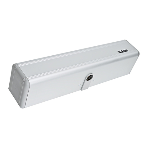
6.0 HOW TO PREPARE AND FIX THE ACTUATOR
Beforefixing theactuatorand arms, firstmake sure thatthe relative bearingstructureis strongandsecure, thatthedoor has
adequatehinges, thatitis notsubjectedto frictionthatcould preventthesystem fromoperatingcorrectly andthatthe points
wherethearmisfixedtothewingarestrongenough.
Ifnecessary,thesepointsmustbereinforcedinanadequateway(additionalplates,strongerhinges,etc.).
Thedoorneedsafloorstoptokeepitopensoastopreventthemechanismsfrombeingdamagedifitispulledviolentlyopen
byhand.Thefloorstopisnotsuppliedwiththeactuatorandmustbeprocuredbytheinstaller.
Thearm can beconnectedto either sideofthe mechanical bodyofthe
actuator. This means that the direction of the opening movement can
beselected.Theconnectionsideofthe armis identifiedby thelabelon
themechanicalbody.Thisshowstheopeningdirectionofthepin. Bear
in mind which type of arm (either sliding or articulated) and fixing
method(onthewallorwing)willbeused.
The actuator has two closing plugs for the pin outlets, of which one is
brokenthroughtoallowthe pin to pass while the other remains whole.
Switch them if the arm connection uses the shaft outlet with the whole
plug.
Remove the aluminium cover from its housing by pulling strongly
upwards,withoutpressingonthesidesifpossible.
Remove the actuator from its wrapping and make sure that it is in a
perfectcondition.
Removethescrewsthatholdthecoverinplace.
7
The following pages describe the ways in which the actuator is used,
withboththearticulatedarmandslidingarm.
There are two tables for each type of fixing method, one called
“SPEED”andtheothercalled“POWER”.
The basic difference between the two is the distance at which the
actuator is fixed in relation to the wing hinge, which either achieves
more speed and less power (”SPEED”) or more power and less speed
(”POWER”).
Comply with the tables for the distance measurements and holes to
make,orusethedrillingtemplatesinscale1:1suppliedwiththearms.

8
NOT Utilizable Length and weight
Utilizable Length and weight
with different fixing sizes
1)
1) Fixing drawings available on request
0500 1000 1500 mm
50
100
120
150
Kg
0 ....250 mm
261 220
B
A+C
B+C
A
X=12.5 mm
X=36.5 mm
X=60.5 mm
(standard)
X=84.5 mm
261
69
115 115123
23 123
106
546
261
6
220 50
37
X18.5
12
ARTICULATE PUSH ARM
7.0 TECHNICAL DRAWINGS

9
B
A+C
B+C
A
X=51.5 mm
X=75.5 mm
X=99.5 mm
X=123.5 mm
(standard)
69
115 115123 123
106
546
23
261
20.5
0..200
261
18.5
12
X
SLIDE PULL ARM
1)
0500 1000 1500 mm
50
100
120
150
Kg
1)
NOT Utilizable Length and weight
Utilizable Length and weight
with different fixing sizes
Fixing drawings available on request
9 mm

10
8.0 ARM CONNECTION
Warning: strictlycomplywith the stepsdescribedwhen fixing thearms.Only remove thespringpreload locking screwwhen
specified in the instructions. Removal of the spring preload locking screw causes the pulleys and gears in the actuator to
move.Keepyourfingersandotherpartsofthebodywellawayfromthemovingpartsduringthisoperation!
Onlycarryout this operationafterhaving disconnected theactuatorfrom the electricpowersource
After having fixed the actuator and arm as shown in the diagrams on the previous pages (or using the drilling template in
scale1:1suppliedwitheacharm),connectthearmtotheoutputshaftoftheactuatorasdescribedinthefollowingsteps:
8.1 Choice of the spring load
The closing spring will have been preloaded in the factory with a
standardvalue, indicated by theredmark on thebeltwhich matches
thered mark onthe pulley (seefigurealongside). Makesurethat this
condition has been complied with when the product is installed. If
thisisnotthecase,complywiththeinstructionsinchapter3)onpage
21inordertobringthepreloadbackwithinthestandardvalue.
Although the preload is fixed, the power exercised by the spring
duringtheclosingphasecanbeselectedinthefollowingway:
Connect the arm to the output shaft with the wing fully open so as to
loadthespringtotheminimum.
Connectthearmtotheoutputshaftwiththewingfullyclosedsoasto
loadthespringtothemaximum.
Connection in an intermediate position loads the spring to a
proportionallyintermediatevalue.
Make sure that the puller nut screwed into the tapered end is
positionedfullydownwards,asshowninthefigure.
Makesurethattheholeplughasbeenfittedontheframe.
Connectthetaperedendofthearmtotheprojectingpin.
Insertthefixingscrewandtightenitstrongly.
8.2 How to fix the tapered end of the arm
8.3 Spring release
Warning:
When this operation is carried out, the components and door arm
could start to move. Keep your fingers and other parts of the body
well away from moving parts during this operation, or keep the wing
blockedmanually.
Move the spring locking screw from the locked position to the
released position, as described in the figure alongside. The door is
now free to close by means of the spring. Make sure that the door
closes completely even when only open to a few degrees. If this fails
to occur, repeat the operations described in this chapter, but
increase the closing force as illustrated in section 8.1. Comply with
theinstructionsinthefollowingsectiontodisconnectthearm.
BELT
REFERENCE PULLEY
REFERENCES
FREE

11
9.0 ARM REMOVAL
Warning:
Strictly comply with the steps described when removing the arms. Only remove the screw that fixes the tapering pin and
tightenthepullernutwhenspecifiedintheinstructions.Removalof the screw that fixes the tapered pin and use of the puller
nutmaycausethepulleysandgearsintheactuatortomoveunless theclosingspringhasbeenpreviouslylocked.
Keepyourfingersandotherpartsofthebodywellawayfromthemovingpartsduringthisoperation!
9.1 How to restore the standard preload and lock the spring
Before you remove the arm, you must restore the spring load to its
standard value, whereby the red mark on the belt matches the red
mark on the pulley (see figure alongside), and lock the spring in this
position. To do this, move the door by hand until this condition has
beenobtainedandtheredmarksonthebeltandpulleymatch.
Move the locking screw from the free position to the locked position
andmakesurethatthescrewfitsintothelockingholeinthepulley.
9.2 How to extract the tapering pin
Removethefixingscrewfromthetaperingpin.
Tighten the release nut upwards until the pin has been completely
removed.
LOCKED
BELT
REFERENCE PULLEY
REFERENCES

12
10.0 EXTENSION SHAFT
Where the conical shaft height should be not sufficente for the
application,
Isavailableanextensionshaft (optional)toincreasethisheight.
Foravailableheights refertoparagraph7.0
Firstofalldeconnectthearmfromtheconicalconnectionbyunscrew
thetwoheadscrews.
Settheextensionshaftintheconicalconnectionlikeinfigure.
Remembertokeepthemainscrewinsideconicalconnection.
Fixtheextensionshaftontheconicalconnectionbytwoscrewsupplied
withtheextension.
Setthearmontheextensionandfixtoit bythetwooriginalscrews.
Aboutarmconnectionandarmremovalrefertopreviousparagraphs.

13
MAINTENANCE PROGRAM
Maintenanceprogramforswing door NEPTIS/LE:
Each6month:
!Attention-Beforework ontheoperator cutmainpower line.
-Checkthatall securing screwsarewell tightened.
-Cleanandlubricate moving andslidingcomponents.
-Lubricateclosingspring if present.
-Checkwiringconnections.
-Checkthatarm connection screwarewell tightened.
-Check that door leaf are stable and the movement is steady, without friction from full
opentofull close position.
-Checkthecondition of thehingesand lubricate it.
-Checkthatspeeds, timing,and safety functionsarewelladjust.
-Checkthatsafety and activationsensorare properly functioning.
!Attention-Anypartthat appeardamagedorwornmustbechanged.
Forspare partssee thesparepartlist.

notes

ELECTRONIC
SECTION
NEPTIS/LE
Nepti
Nepti
S

NEPTIS/LE
1) ELECTRICAL CONNECTIONS
16
AUXAUX
1
!TERMINALBOARDM1
230 V.a.c. power supply: phase wire to terminal F, neutral wire to terminal N + ground connection.
The line is protected by the 5A fuse F1.
!TERMINALBOARDM2
Terminals 1-3-4 = connection of the FUNCTION SELECTOR switch installed on the
side of the device.
centralcontactoncommonterminal3;
contactmadeinposition|ontheAUX1terminal;
contactmadeinposition||ontheAUX2terminal;
Terminals2-3 =N.C.inputofthesafetyPHOTOCELL.
Activates during the closing phase and reverses the door's direction.
Terminals5-7 = N.C.inputoftheopeningsafetySENSORmod.SSS1.
The door stops if an obstruction or person is detected, and only starts opening
again when the sensor has been released.
Terminals6-7 = EMERGENCYN.C.input.Opensthedoorinanycondition.
Canalsooperateinthesteppingmode(seesect.7).
Fig.1
Nepti
Nepti
S

17
E
I
!TERMINALBOARDM3
Terminals 8-11 =N.O.EXTERNALRADARinput.Commandsthedooropeningfunction.
It is excluded by the digital selector in the night lock or exit only functions.
It is excluded by the manual selector in the night lock or exit only functions.
Can also operate as an opening only input (see sect. 7).
Terminals 9-11 = N.O. INTERNAL RADAR input. Commands the door opening function.
It is inhibited by digital selector in the night lock or entrance only functions.
It is inhibited by manual selector in the night lock function.
Can also operate as a closing only input (see sect. 7).
Terminals 10-11 = N.O. START input. Commands the door opening function and starts the initial set-up.
It is inhibited by digital selector in the night lock function.
It is inhibited by manual selector in the night lock function.
Can also operate in the stepping mode (see sect. 7).
!TERMINALBOARD M4
Connectiontodigitalselector.Usea4-poleflex(0.5mmindiameter),maintainingthesamesignalmatchbetweenselectorand
controlunit.Maximumcablelength20meters.
Route the connection cable well away from sources of electrical interference to prevent false displays on the
selector.
Terminal 12 = 0 (powering negative)
Terminal 13 = DATA ITEM
Terminal 14 = +12 Vdc (powering positive)
Terminal 15 = G (ground)
Use the 4-pin terminal board in the selector kit.
WARNING!
Theselector kit includes the “LOGIC TAST” interface board, which must be fitted into connectorJ8 (see fig.2) so as to allow the
selectortoworkwiththe"NEPTIS/LE”controlunit.
!TERMINALBOARDSM5-M6=DedicatedtoconnectionofphotocellPRJ38capsules;seesect.12foroperationmode.
!TERMINALBOARDM7
Terminals16(-)-17(+) = 24Vdcoutput,max.20W,forpoweringexternalaccessories.
Led L2 indicates that the line is powered a 24V.
!TERMINALBOARDM8
Terminals18-19 =N.O.cleancontactofrelayRL1thatcanbeusedtoconnectanelectro-lock.
Take the power from terminals 16 ( - ) and 21 ( + ) in the case of a 24 V electro-lock.
Terminal 20 =Signal output of the OPEN COLLECTOR type, active when door is open or moving; max. load
100mA.
Thepositivesignalistakenfromterminal17.
CONNECTORSJ1-J2 =powertransformerconnection:primaryonJ1,secondaryonJ2.
CONNECTORS J4-J10 = wiring of signal conductors between electrical connection part PWN and logic
logic part LGN of the electronic control unit.
CONNECTOR J6 = encoder connection.
CONNECTOR J7 = motor connection.
Connector16(-)e21(+) =output24Vdcforthepoweringoftheelectrolock(24V).
CONNECTORS J5-J11 = connection of the powering conductors between the parts PWN e LGN of the control unit..
The powering line LGN is visualized by the LED L1.

18
2)DESCRIPTION OFLOGICPART LGNOF THECONTROL UNIT
Fig.2
DL1 DL2 = displaythesignalsfromtheencoder'ssensor.
DL3 = indicates that main microprocessor MP1 is operating correctly by flashing very fast.
If the led is off or flashes slowly, this means that the logic board is faulty.
CONNECTOR J8 = connection for the LOGIC TAST interface module of selector.
CONNECTOR J9 = connector for the photocell board.
CONNECTOR J13 = connection between the MASTER and the SLAVE control unit for two-wing swing door
(see sect. 13). Use the MASTER/SLAVE wiring for "NEPTIS/LE” mod.WR3MS.
CONNECTORJ8 =connectionfortheLOGICTASTinterfacemoduleofselector.
CONNECTOR J9 = connector for the photocell board.
Dip switch S1 = selects the operating programs of the control unit (see sect. 6).
Potentiometer = calibration of the operating parameters (see sect. 8).
Buzzer = horn.
MP1 = microprocessor with label indicating the software version.
BRIDGE J12 = it selects the speed of closing of the door in absence of main power:
OPENBRIDGE =highspeed
CLOSEDBRIDGE =lowspeed
OPENING
SPEED
CLOSING
SPEED
SENSOR
DISTANCE
POWER
PAUSE LGN-LE
PHOTOCELL CONTROL
BUZZER
LOGIC TAST
MODULO SELETTORE SDN1
NEPTIS-LE
ENCODER
J6
J13 J8
X1
DIP SWITCH
MP1
MOTOR
J7
J10
J9 J11
ENCODER
DL2 DL1
ON
DL3
WD
J12

The actuator is supplied with the reclosing spring preloaded with a
standard value, whereby the red mark on the belt matches the red mark
onthepulley(seefigurealongside).
If, during operation, the arm is accidentally disconnected without the
spring having been returned and locked in the standard position, this
latterwillrelievewellbeyonditsstandardvalue.
Strictly comply with the following instructions to return the spring to the
correctposition:
a) Completely disconnect the arm from the projecting pin if this latter is
stillinserted.
b) Make sure that the FUNCTION SELECTOR switch alongside the
actuatorisinthecentral“0” position.
If the manual selector is installed, set the knob to the door free
position .
If the digital selector is installed, make sure that indicator lights
and areoff.
c) Carefully move power limiting potentiometer Tm4 to about half of its
travelandpowerthecontrolunit.
d) Setdip-switch6ofMinidipS1totheOFFposition.
e) Switchoffthemainspowersupply(230V)forabout5seconds.
f) Turn on the mains power again and wait for an acoustic signal
(“BEEP”).
g) Setdip-switch6ofMinidipS1totheONposition.
h) Switchoffthemainspowersupply(230V)forabout5seconds.
i) Turn on the mains power again and wait for an acoustic signal
(“BEEP”)
j) Setdip-switch6ofMinidipS1totheOFFposition.
k) Switchoffthemainspowersupply(230V)forabout5seconds.
l) Turn on the mains power again and wait for an acoustic signal
(“BEEP”)
m)Press button PS1 (START) on board PWN. The control unit will issue 5
beeps and will begin the spring loading manoeuvre in the constant
pressure mode (the movement will stop when the start button is
releasedandwillcontinuewhenstartispressedagain).
n) Bring the spring load back to the standard value shown when the red
mark on the belt matches the red mark on the pulley (see figure
alongside),thenlockthespringinthisposition.
l) Move the locking screw from the free position to the locked position,
makingsurethatitfitsintothelockingholeonthepulley.
19
F1
3) HOWTORESETTHESPRINGPRELOAD
Onlyreadthis sectionif,duringtheinstallation phase,thearmisaccidentallydisconnectedwithout thespringbeingreturnedto
thestandardpositionandrelocked.Ifthishappened,thespringwouldberelievedwellbeyonditspresetlevel.
m)!! WARNING, the INITIAL SET-UP will be cancelled after these operations and will therefore have to be made
againattheappropriatetime,asdescribedinsection4.
BELT
REFERENCE PULLEY
REFERENCE
LOCKED

4)HOW TOSET THEDEVICE AT WORK(INITIAL SET-UP)
After having fixed the device to the door and loaded the spring (only for the SW version), move the wing as far as it will go by
hand.Makesurethatthemovementissmooth,fluid,withoutfrictionandthatitendswiththedoorfullyagainstanendrabbet.
Proceed with the initialization phase (initial set-up). This operation is obligatory as it allows the control unit to acquire the
stop points. Strictly comply with the following instructions:
a) Make sure that the device is not powered and that the dip-switches of S1 are in the OFF status.
b) Movedip-switch6ofS1totheONpositionandtheFUNCTIONSELECTORswitchto“|”(dayfunctions).
c) Movedip-switch4ofS1totheONposition,butonlyiftheelectro-lockisinstalled.
d) Setthedoortotheclosingstatus.
e) Powerthe device: the power unit gives 3 bips, the last two immediately following one another.
WARNING!
Duringtheinitialset-up,thedoormoveswithmoreforcethanthenormaloperatingconditions.Proceedwithcareandkeepwell
clearofthedoor'soperatingrange.
f) PressbuttonPS1(startinput)onboardPWN.
g) thedoorwillcompleteafullopeningcycleatslowspeed.
Oncethismanoeuvrehasterminated,aprolongedBIPwillindicatethattheprocedurehasended.
Doorclosingoccursattheendofthepausetime.
the door will push lightly closed and will then proceed with a complete
opening/closingcycleatslowspeed.
Oncethedoorhasclosed,aprolongedBIPwillindicatethattheprocedurehasended.
IMPORTANT: during the initializing phase, there must be no obstructions in the manoeuvring area and the door
mustnotbehelpedalongbyhand.
Oncethe initial set-uphasterminated, make anopening manoeuvre bymeansof acommandinput and checkthe movements
accordingtothedefaultsettings.
SAFETY: The thrusting force of the door can be checked during the starting phase and at various stages of its movement by
listening to the buzzer and the indications given by the warning light of digital selector. The effective intensity of this
thrustingmovementcanbecheckedbyobstructingthemovementinordertostopthedoorandreverseitsdirection.
Potentiometer TM4onboard LGN can beusedto vary thepowerof the door thrustingactionand to accurately settherequired
activationlimit.
Abriefsignalfromthebuzzerduringthestartingupphaseonly,indicatesthatthethrustingpowersettingisgood.
Setdip-switch6ofS1totheOFFpositiontoinhibitthepowerlimitingbuzzer.
Lastly, select the required functions, set the speed, time settings and distances to optimize the operation of the door to suit
personalrequirements.
4.1)HOW TOCANCEL APREVIOUS INITIALSETUP
Ifwingtravel,doorweightorspringloadingarechanged,theinitializingphaseofthecontrolunitmustberepeated.
Proceedinthefollowingway:
1. Disconnectthepowersource,thensetdip-switch6ofS1totheOFFstatusandpowerthecontrolunit.
2. After the initial bip, set dip-switch 6 of S1 to the ON status and disconnect the power source.
3. Power the control unit, wait for the initial bip and set dip-switch 6 of S1 to the OFF status.
4. Shut off the power supply;
5. The previous initial setting will be cancelled;
6. Repeat the previous operations from point a) to point g) to enter the initial setup again.
ifdip5OFF(closingonlybyspring):
if dip 5 ON (closing by spring and by motor) :
20
L1
Table of contents
Other Label Door Opening System manuals

Label
Label T-NFC User manual

Label
Label Neptis SLT-B User manual

Label
Label NEXT 75 User manual

Label
Label ETERNA 70 User manual

Label
Label NEPTIS PLUS User manual

Label
Label Neptis SMP User manual

Label
Label Neptis SMP User manual

Label
Label EVOLUS Manual

Label
Label NEXT 75 User manual

Label
Label NEXT 120s User manual
Popular Door Opening System manuals by other brands

Entrematic
Entrematic EMSL user manual

Power Master
Power Master T Installation and owner's manual

Entrematic
Entrematic Ditec VALLOKA installation manual

Entrematic
Entrematic Ditec VALLOKB installation manual

DoorHan
DoorHan ARM 320 Installation and operating manual

Hettich
Hettich Easys 200 operating instructions