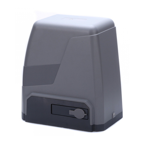
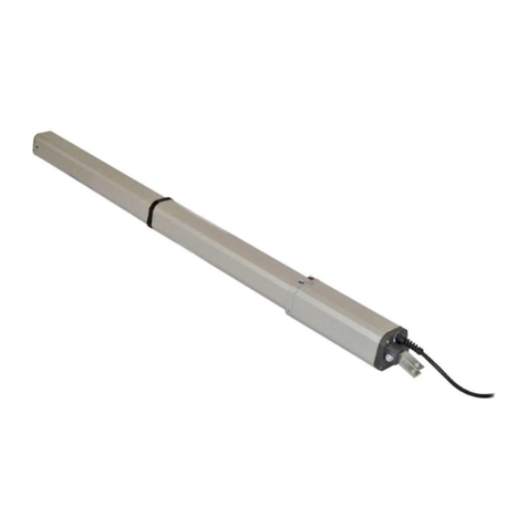
EUROLAIKAS SL500DC User manual

EUROLAIKAS
Garažo ir kiemo vartai, vartųautomatika, kelio užtvarai, vartųpulteliai
, automatikos dalys
Laisvės pr. 121-65
, Vilnius. Tel. 8 (5) 246 33 33,
mob. +3706 824 2443
el. paštas: info@eurolaikas.lt, www.eurolaikas.lt
E-PARDUOTUVĖ: www.vartai.eu
SL500DC/SL800DC
Sliding Gate Opener
User Manual

EUROLAIKAS
Garažo ir kiemo vartai, vartųautomatika, kelio užtvarai, vartųpulteliai
, automatikos dalys
Laisvės pr. 121-65
, Vilnius. Tel. 8 (5) 246 33 33,
mob. +3706 824 2443
el. paštas: info@eurolaikas.lt, www.eurolaikas.lt
E-PARDUOTUVĖ: www.vartai.eu
1
CONTENTS:
1. Safety Instruction………………………………………………………………...………………………………………………………1
2. Packing List…………………………………………………………………………………………...………………………………….2
3. Technical Parameters………………………………………………………………………..……………………….…………………3
4. Installation………………………………………………………………………………...………………………………………………4
4.1 Installation Drawing………………………………………………………………..…….…………………………………………4
4.2 Si e of Main Machine and Accessories…………………………………………………………………….……………………5
4.2.1 Si e of Main Machine……………………………………………………………………………...………………………5
4.2.2 Si e of Mounting Plate…………………………………………………………………………...……………………..…5
4.3 Installation Procedures………………………………………………………………………………….…………………………6
4.3.1 Preparation before Installation……………………………………………..……………………………….……………6
4.3.2 Main Machine Installation…………………………………………………………………………..………………….....7
4.3.3 Gear Rack Installation………………………………………………………………………………………..…………...7
4.3.4 Origin Sensor Kit Instruction……………………………………………………………..…………….…………………9
5. Control Board Wiring and Adjustment. ………………………………………………………...……………………………...…….10
5.1 Terminal Wiring Instruction…………………………………………………………………...………………….………………10
5.2 Operation Interface Instruction……………………………………………………………………………………………..……11
5.3 Travel Limit Position Setting……………………………………………………………………………………………….…….12
5.3.1 Operation Instruction for Travel Limit Position Setting…………………………………………………..…………...12
5.3.2 Travel Setting Tips……………………………………………………………………………………………..………...13
5.4 Remote Control Management………………………………………………………………………………………….………..14
5.4.1 Single Button Mode Learning (L1) …………………………………………………………………………..………...15
5.4.2 Three Button Mode Learning (L2) …………………………………………………………………………..…………16
5.4.3 Pedestrian Mode Function on Remote Control (L3) …………………………………………………………...…….17
5.4.4 Remote Control Delete (L4) ………………………………………………………………………………..…………..18
5.4.5 Remote Control Intelligent Learning……………………………………………………..…………………………….19
5.5 Basic Menu Setting……………………………………………………………………….………………………………………20
5.5.1 Running Speed Setting (L1) …………………………………………………………..………………………………..20
5.5.2 Slow Stop Speed Setting (L2) ……………………………………………………..…………………………………...21
5.5.3 Auto-reverse When Meeting Obstacles Setting (L3) ………………………………………..……………………….22
5.5.4 Slow Stop Distance Setting (L4) …………………………………………………………..…………………………...23
5.5.5 Auto-close Function Setting (L5) ……………………………………………………………………………..………..24
5.6 Advanced Menu Setting……………………………………………………………………………………….…………………25
5.6.1 Working Mode Setting (L1) …………………………………………………………..…………………………………26
5.6.2 Acceleration Setting (L2) ………………………………………………………………..……………………………...27
5.6.3 Start-up Delay Setting (L3) ………………………………………………………….…………………………………28
5.7 Manual Control Mode…………………………………………………………………………….………………………………30
5.8 Battery Level Checking………………………………………………………………………….……………………………….30
5.9 Restore Factory Setting……………………………………………………………………….…………………………………31
6. Others………………………………………………………………………………………………..………………………………….32
6.1 Maintenance………………………………………………………………………………….…………………………………...32
6.2 Troubleshooting…………………………………………………………………………………………………………….……..32

EUROLAIKAS
Garažo ir kiemo vartai, vartųautomatika, kelio užtvarai, vartųpulteliai
, automatikos dalys
Laisvės pr. 121-65
, Vilnius. Tel. 8 (5) 246 33 33,
mob. +3706 824 2443
el. paštas: info@eurolaikas.lt, www.eurolaikas.lt
E-PARDUOTUVĖ: www.vartai.eu
2
Dear users,
Thank you for choosing this product. Please read this manual carefully before installation and use. Please do not forget to
include this manual if you send the product to a third party.
1. Sa ety Instruction
Please read this manual carefully before installation, in which involves with important information about installation、using、
maintenance and safety.
Any undefined operations under this manual is not allowed, incorrect using may damage the product even causing the injuries
or property losses.
To consider the possible danger during the installation or using of this product, installation must strictly comply with the
construction standard and electrical operating procedure, especially the following:
Before installation, please make sure the power voltage being used matches with the supply voltage of this product.
Please check if the leakage protection switch is installed and the grounding system is correct.
Please check if additional equipments or materials are required to meet the specific requirements.
The disposal of packaging material must comply with the local regulation.
Please do not change any parts except for those defined under this manual. Any undefined changes may cause the
malfunction. Any damages to the product arising there from shall be beyond the liability of the company.
Please do not leak water or any liquid into the controller or any other open devices. Please disconnect the power
immediately if any of these mentioned cases happened.
Please keep this product away from heat and open fire. Or it may damage the components; cause the failure or other
ha ards.
Please make sure there is no vehicles、passengers or objects passing through while the sliding gate is moving.
Anti-clip equipment like infrared protection sensor must be installed to avoid injuries to person and property losses. The
company shall not be liable for any damage or accident arising there from.
The installation、using and maintenance of this product must be carried out by professionals.
Children are not allowed be touch the control devices or play with the remote controls.
A warning sign must be placed somewhere on the sliding gate according to the national standard.
Please keep this instruction properly for future reference.

EUROLAIKAS
Garažo ir kiemo vartai, vartųautomatika, kelio užtvarai, vartųpulteliai
, automatikos dalys
Laisvės pr. 121-65
, Vilnius. Tel. 8 (5) 246 33 33,
mob. +3706 824 2443
el. paštas: info@eurolaikas.lt, www.eurolaikas.lt
E-PARDUOTUVĖ: www.vartai.eu
3
2. Packing List (Standard)
No. Picture Name Quantity
1
Main machine 1
2
Manual release key 2
3
Remote control 2
4
Accessories box 1
4-1
Origin marker and bracket 1
4-2
Origin marker mounting screw
M6x16
2
4-3
Hexagon head bolt M8x25 4
4-4
Flat washer Ø8 4
4-5
Spring washer Ø8 4

EUROLAIKAS
Garažo ir kiemo vartai, vartųautomatika, kelio užtvarai, vartųpulteliai
, automatikos dalys
Laisvės pr. 121-65
, Vilnius. Tel. 8 (5) 246 33 33,
mob. +3706 824 2443
el. paštas: info@eurolaikas.lt, www.eurolaikas.lt
E-PARDUOTUVĖ: www.vartai.eu
4
2. Packing List (Optional)
No. Picture Name Quantity
1
Galvani ed gear rack 1m/pc
2
Nylon gear rack 1m/pc
3
Infrared sensor 1
4
0
8
5 6
97
4
1 2 3
Wireless keypad 1
5
Alarm lamp 1
6
Mounting plate 1
3. Technical Parameters
Model SL500DC SL800DC
Power supply 220V/50H ;110V/60H 220V/50H ;110V/60H
Motor power 150W 170W
Gate moving speed 16-18m/min 16-18m/min
Maximum loading weight 500Kg 800Kg
Remote control distance ≥30m ≥30m
Remote control mode Single button mode/Three button mode Single button mode/Three button mode
Limit switch Electronic limit switch Electronic limit switch
Noise ≤60dB ≤60dB
Working duty S2, 20min S2, 20min
Recording of up remote controls 100 100
Frequency 433.92 MH 433.92 MH
Working temperature -20°C ~ +70°C -20°C ~ +70°C

EUROLAIKAS
Garažo ir kiemo vartai, vartųautomatika, kelio užtvarai, vartųpulteliai
, automatikos dalys
Laisvės pr. 121-65
, Vilnius. Tel. 8 (5) 246 33 33,
mob. +3706 824 2443
el. paštas: info@eurolaikas.lt, www.eurolaikas.lt
E-PARDUOTUVĖ: www.vartai.eu
5
Package weight 10Kg 11Kg
Battery specification 12V/9Ah 12V/9Ah
4. Installation
SL500DC/SL800DC sliding gate opener is applicable to the type of sliding gate which weight is less than 500kg/800kg,
length is shorter than 12m. The drive mode adopts the rack and gear transmission. This gate opener must be installed
inside the enclosure or yard for protection.
4.1 Installation Drawing
Figure 1
1. Gate opener 3. Gate 5. Alarm lamp (optional) 7. Gear rack
2. Wireless keypad (optional) 4. Infrared sensor (optional) 6. Safety stopper 8. Origin marker
9.
Remote control

EUROLAIKAS
Garažo ir kiemo vartai, vartųautomatika, kelio užtvarai, vartųpulteliai
, automatikos dalys
Laisvės pr. 121-65
, Vilnius. Tel. 8 (5) 246 33 33,
mob. +3706 824 2443
el. paštas: info@eurolaikas.lt, www.eurolaikas.lt
E-PARDUOTUVĖ: www.vartai.eu
6
4.2 Size o Main Machine and Accessories
4.2.1 Size o Main Machine
Figure 2
4.2.2 Size o Mounting Plate
Figure 3

EUROLAIKAS
Garažo ir kiemo vartai, vartųautomatika, kelio užtvarai, vartųpulteliai
, automatikos dalys
Laisvės pr. 121-65
, Vilnius. Tel. 8 (5) 246 33 33,
mob. +3706 824 2443
el. paštas: info@eurolaikas.lt, www.eurolaikas.lt
E-PARDUOTUVĖ: www.vartai.eu
7
4.3 Installation Procedures
4.3.1 Preparation be ore Installation
Please make sure that the sliding gate is correctly installed, the gate rail is in hori ontal, and the gate can be manually
pushed smoothly before installing the gate opener.
Cable installation
In order to guarantee the normal operation of the gate opener and protect the cables from damage, please bury the motor
power cable and controlling cable separately with two PVC tubes.
Concrete pedestal
Please precast a concrete pedestal in si e 500mm x 300mm, depth 250mm, so as to firmly install SL500DC/SL800DC
gate opener. Please make sure the distance between the gate and gate opener is appropriate be ore
casting the pedestal.
Embedded screws
Concrete
Power line
Mounting plate
Foundation bolt
Figure 4
Concrete
Power line
Mounting plate
Figure 5

EUROLAIKAS
Garažo ir kiemo vartai, vartųautomatika, kelio užtvarai, vartųpulteliai
, automatikos dalys
Laisvės pr. 121-65
, Vilnius. Tel. 8 (5) 246 33 33,
mob. +3706 824 2443
el. paštas: info@eurolaikas.lt, www.eurolaikas.lt
E-PARDUOTUVĖ: www.vartai.eu
8
4.3.2 Main Machine Installation
a) Dismantle the plastic housing of the main machine before installation, keep the relevant fasteners properly;
b) Please prepare a power cable for connecting the main machine to power supply (the number of power supply cable
cores should not be less than 3 PCS, the sectional area of cable core should be over 1.5mm² and the length should be
determined by users according to the situation of the installation spot.)
c) Please unlock the main machine before installation, the unlock method is: take out the key cover, insert the key to
open the manual release bar till it opens to 90° as shown in Figure 6. Then rotate the output gear and the gear can be
rotated easily.
Turn on 90¡ã
Figure 6
4.3.3 Gear Rack Installation
Fix the mounting screws to the gear rack.
Put the gear rack on the output gear of the main machine; make the rack engage with the output gear then weld the
mounting screws to the gate (each screw marks with a solder joints in advance).
Manually move the gate (gate should be moved smoothly after machine unlocked) to check whether there is a fit
clearance between gear rack and output gear, as shown in Figure 7.
Weld all the mounting screws to the gate firmly.
Make sure that all racks are on the same straight line.
Pull the gate after gear rack installed, make sure the entire trip is flexible without any stuck.

EUROLAIKAS
Garažo ir kiemo vartai, vartųautomatika, kelio užtvarai, vartųpulteliai
, automatikos dalys
Laisvės pr. 121-65
, Vilnius. Tel. 8 (5) 246 33 33,
mob. +3706 824 2443
el. paštas: info@eurolaikas.lt, www.eurolaikas.lt
E-PARDUOTUVĖ: www.vartai.eu
9
Figure 7
The fit clearance of output gear and rack is shown in Figure 8 below:
1-21-2
GearGear rackrack
OutputOutput geargear
mmmm
Figure 8
Warnings
• To ensure safety, please install safety stoppers on both ends of the rail to prevent the gate from running out of the
rail. Before installing the main machine, make sure that the safety stoppers are installed in place, and check
whether it has the function of preventing the gate from running out of the rail or safety range.
• Please make sure that the main machine and its components have good mechanical properties, and the gate can
be operated flexibly when manually moved before installing the main machine.
• Please note that for this product, one control can only drive one main machine, otherwise, the control system will be
damaged.
• Earth leakage circuit breaker must be installed in where the gate movement can be seen, and the minimum

EUROLAIKAS
Garažo ir kiemo vartai, vartųautomatika, kelio užtvarai, vartųpulteliai
, automatikos dalys
Laisvės pr. 121-65
, Vilnius. Tel. 8 (5) 246 33 33,
mob. +3706 824 2443
el. paštas: info@eurolaikas.lt, www.eurolaikas.lt
E-PARDUOTUVĖ: www.vartai.eu
10
mounting height is 1.5m to avoid being touched by children.
• After installation, please check whether the mechanical property is good or not, whether gate movement after
manual unlocking is flexible or not, whether the installation for infrared sensor (optional) is correct and effective.
4.3.4 Origin Sensor Kit Instruction
The origin sensor kit is consisted of origin marker and origin sensor. The origin marker should be mounted to the gear
rack by the installer when installing the gate opener. The origin sensor was installed inside the machine in the factory.
Origin sensor kit function:
During gate opening and closing, the gate opener will calibrate the opening and closing limit position through the origin
sensor kit to reali e a precise travel positioning.
Please follow 5.3 Travel Limit Position Setting to set and save the opening and closing limit position. When the power
supply is accidentally failed, the gate opener will restore to its setting travel through the origin sensor kit.
Installation requirement on the origin marker:
1. Origin marker should be installed to the gear rack, the installation position should be around 1 meter away from the
closing limit position.
2. The installation clearance between the origin marker and the gate opener should be less than 10mm, and should
mount it near the opener as soon as possible.
3. Do not move or remove the origin marker after the opening and closing limit position are settled.
OutputOutput geargear
GateGate
GearGear rackrack
OriginOrigin markermarker bracketbracket
OriginOrigin sensorsensor
MotorMotor covercover
OriginOrigin markermarker OriginOrigin markermarker
Figure 9

EUROLAIKAS
Garažo ir kiemo vartai, vartųautomatika, kelio užtvarai, vartųpulteliai
, automatikos dalys
Laisvės pr. 121-65
, Vilnius. Tel. 8 (5) 246 33 33,
mob. +3706 824 2443
el. paštas: info@eurolaikas.lt, www.eurolaikas.lt
E-PARDUOTUVĖ: www.vartai.eu
11
OriginOrigin sensorsensor
OriginOrigin markermarker
Figure 10
5. Control Board Wiring and Adjustment
5.1 Terminal Wiring Instruction
L0 L1 L2 L3 L4 L5
ROG SET
SOL BAT OWER
+ - + -
V+V-
V+
V- NO COM N C
Infrared receiver Infrared emitter
LAM 12 V G ND IR
+ -
OSC ED ST CO M GND ANT
Alarm lamp 12/24VDC
Antenna
edestrianedestrian ButtonButton
O/S/CO/S/C buttonbutton
StopStop buttonbutton
Hall sensor
Motor 24VDC
Transformer
output: 22VAC
Fuse
:
5A
ower supply
SL500DC Control Board
Direction sensor
input:220VAC / 110VAC
solar charge controller
Solar panel 24V/20W
Figure 11

EUROLAIKAS
Garažo ir kiemo vartai, vartųautomatika, kelio užtvarai, vartųpulteliai
, automatikos dalys
Laisvės pr. 121-65
, Vilnius. Tel. 8 (5) 246 33 33,
mob. +3706 824 2443
el. paštas: info@eurolaikas.lt, www.eurolaikas.lt
E-PARDUOTUVĖ: www.vartai.eu
12
1. Power supply terminal (P7) (Transformer output)
Transformer specification: 240VAC/22VAC or 120VAC/22VAC
Rated power: 120W
2.
Battery and solar panel terminal (P5)
Battery specification: 12V/9AH Solar panel specification: 17V/20W
3.
Origin sensor terminal (P3)
4. Motor terminal (P8)
5. Hall sensor terminal (P6)
6. Alarm lamp and infrared sensor terminal (P4)
Alarm lamp type: LED Voltage: 12/24VDC Infrared sensor: NC
7. External button and antenna terminal (P1)
External button: NO
5.2 Operation Inter ace Instruction
Figure 12
Indicator Lights:
L0 (Green): Indicating the control board working status and menu status.
L1-L5 (Red): Indicating the settings, parameters, errors and battery level.
Setup Buttons
PROG: Enter into or exit the setting menu.
- and +: Function select and parameter adjust.
SET: Enter into the selection, confirm the setting.

EUROLAIKAS
Garažo ir kiemo vartai, vartųautomatika, kelio užtvarai, vartųpulteliai
, automatikos dalys
Laisvės pr. 121-65
, Vilnius. Tel. 8 (5) 246 33 33,
mob. +3706 824 2443
el. paštas: info@eurolaikas.lt, www.eurolaikas.lt
E-PARDUOTUVĖ: www.vartai.eu
13
Note:
Press the setting button for a short while (within 1 sec.) or long press the button (over 3 sec.) will be for different
functions.
5.3 Travel Limit Position Setting
Precondition:
1. Before setting the limit position, please make sure that the gate is completely opened.
2. Please install the origin magnet on the middle of the gate, which should not be moved or removed thereafter.
Note:
The travel limit position must be settled according to the gate travel length after the first installation of the gate opener.
5.3.1 Operation Instruction or Travel Limit Position Setting:
A. Operation Instruction
1. Enter into Setting Mode:
a. Press “-” button for 3 sec. to enter into travel limit position setting. All indicator lights L1-L5 will flicker
simultaneously.
b. Press “SET” button once to confirm to reset the travel limit position. The indicator lights will be on in sequence
from L5 to L1.
2. Gate Closing Limit Position Setting:
c. Press and hold “-” button to enable the gate to run to its appropriate closing limit position. Then release the “-” button
to stop running. Through pressing the “-” or “+” button, the closing limit position can be adjusted accurately. (I the gate
runs to its opening direction a ter pressing the “-” button, please press “PROG” button to exit the travel limit
position setting irst, then exchange the motor wires and re-start to set the limit position)
d. Press “SET” button to confirm the closing limit position. The indicator lights will be on in sequence from L1 to L5.
3. Gate Opening Limit Position Setting:
e. Press and hold “+” button to enable the gate to run to its appropriate opening limit position, then release the “+”
button to stop running. Through pressing the “-” or “+” button, the opening limit position can be adjusted accurately
f. Press “SET” button to save the settings and exit automatically. The indicator lights L1-L5 will be on for one sec.
B. Operation Graphic Illustration
1. Enter into Setting Mode:

EUROLAIKAS
Garažo ir kiemo vartai, vartųautomatika, kelio užtvarai, vartųpulteliai
, automatikos dalys
Laisvės pr. 121-65
, Vilnius. Tel. 8 (5) 246 33 33,
mob. +3706 824 2443
el. paštas: info@eurolaikas.lt, www.eurolaikas.lt
E-PARDUOTUVĖ: www.vartai.eu
14
LED
L1-L5 flicker si ultaneously
SET
Press "SET" button once
LED
sequence fro L5 to L1
Indicator lights will be on in
Press "—" button for 3 sec
2. Gate Closing Limit Position Setting:
Press “—” button to close
LED
at the closing li it position
Release "
—
——
—
" button after arriving
SET
Press “SET” button once
LED
in sequence fro L1 to L5
Indicator lights will be on
3.
Gate Opening Limit Position Setting:
Press “
+
++
+
” button to open
SET
Press “SET” button once
LED
L1-L5 will be on for 1 sec
Release “
+
++
+
” button after reaching
the opening li it position Save and exit auto atically
Figure 13
5.3.2 Travel Setting Tips:
During the travel setting process, users can check the travel limit position settings through the indicator lights status.
(Table 1 Travel Setting Tips)

EUROLAIKAS
Garažo ir kiemo vartai, vartųautomatika, kelio užtvarai, vartųpulteliai
, automatikos dalys
Laisvės pr. 121-65
, Vilnius. Tel. 8 (5) 246 33 33,
mob. +3706 824 2443
el. paštas: info@eurolaikas.lt, www.eurolaikas.lt
E-PARDUOTUVĖ: www.vartai.eu
15
L1 L2 L3 L4 L5
Indicator light status£º
L1 L2 L3 L4 L5
L1 L2 L3 L4 L5
L1 L2 L3 L4 L5
L1 L2 L3 L4 L5
L1 L2 L3 L4 L5
Off On Flicker Status Instruction
Travel for closing is too long 12m
Travel for closing is too short 0.5m
Travel for opening is too long 12m
Travel for opening is too short 0.5m
Origin marker is not detected
L1 L2 L3 L4 L5
L1 L2 L3 L4 L5
STO button is pressed, travel setting is interrupted
Hall sensor signal is not detected
ress ROG to exit the travel setting
L1 L2 L3 L4 L5
Travel limit position setting successfully all on for 1 sec, then off
Table 1 Travel Setting Tips
Note:
1. If there is no action under the limit switch position setting status, system will automatically exit after 20 sec.
2. If need to exit in the process of travel limit position setting, please press “PROG” once to directly exit.
5.4 Remote Control Management
Operation Instruction:
1. Press “+” button for 3 sec. to enter into the first function of remote control management under the control board
standby mode.
2. Different functions can be selected through “+” and “-” buttons.
3. Press “SET” button to enter into the corresponding selection to set the parameters.
L1 L2 L3 L4 L5
Three-Button Mode Learning
L1 L2 L3 L4 L5
edestrian Mode Function
L1 L2 L3 L4 L5
Remote Control Delete
L1 L2 L3 L4 L5
Standby Mode
ress and hold
“
+
”
button for 3 sec
Remote Control Management
Single Button Mode Learning on Remote Control
Figure 14
Remote Control Mode Instruction:
There are two modes available for remote control under the control board for this product. Users may pair the remote

EUROLAIKAS
Garažo ir kiemo vartai, vartųautomatika, kelio užtvarai, vartųpulteliai
, automatikos dalys
Laisvės pr. 121-65
, Vilnius. Tel. 8 (5) 246 33 33,
mob. +3706 824 2443
el. paštas: info@eurolaikas.lt, www.eurolaikas.lt
E-PARDUOTUVĖ: www.vartai.eu
16
control to their requirement under the corresponding mode.
1. Single button mode: Open-stop-close of the gate opener is controlled by only one button on the remote control.
2. Three button mode: Open-stop-close of the gate opener is controlled by three different buttons on the remote control.
5.4.1 Single Button Mode Learning (L1)
Under this mode, one of the remote control buttons that is paired to gate opener can individually control the operation of
one opener. The rest buttons on this remote control can be used to pair to other openers. (Please refer to instruction
5.4.3 for the usage for the forth button on the remote control)
Figure 15
A. Operation Instruction
1. Press “+” button for 3 sec. to enter into remote control management mode. Indicator light L1 will be always on.
2. Press “SET” button once to enter into single button learning mode. Indicator lights L1 and L5 will flicker alternately.
(If an alarm lamp is connected, it’ll flash at the same time)
3. Press the button which is to be learned on the remote control. Indicator lights L1-L5 will be on for 1 sec. (If an alarm
lamp is connected, it’ll be on for one sec.) Learning is complete thereafter.
4. The control board will stay in learning mode after remote control learning successfully, the learning of the remaining
remote controls can be done by repeating the 3
rd
step; Press “PROG” button to exit the learning mode.
B. Operation Graphic Illustration

EUROLAIKAS
Garažo ir kiemo vartai, vartųautomatika, kelio užtvarai, vartųpulteliai
, automatikos dalys
Laisvės pr. 121-65
, Vilnius. Tel. 8 (5) 246 33 33,
mob. +3706 824 2443
el. paštas: info@eurolaikas.lt, www.eurolaikas.lt
E-PARDUOTUVĖ: www.vartai.eu
17
Press "+" button for 3 sec
SET
Press "SET" button once
LED
L1 will be on
LED
L1 and L5 will Press the button which is to be
learned on the re ote control
Press "PROG" button
ROG
Save and auto atically exit
LED
L1-L5 will be on for 1 sec
flicker alternately
Figure 16
5.4.2 Three-Button Mode Learning (L2)
Under this mode, all buttons on the remote control that are paired to gate opener will be separately used for gate
opening、closing and stop. (Please refer to instruction 5.4.3 for the usage for the forth button on the remote control)
Figure 17
A. Operation Instruction
1. Press and hold “+” button for 3 sec. to enter into remote control management mode. Indicator light L1 will be
always on.
2. Press “+” button once to select three button learning mode option. Indicator light L2 will be always on.

EUROLAIKAS
Garažo ir kiemo vartai, vartųautomatika, kelio užtvarai, vartųpulteliai
, automatikos dalys
Laisvės pr. 121-65
, Vilnius. Tel. 8 (5) 246 33 33,
mob. +3706 824 2443
el. paštas: info@eurolaikas.lt, www.eurolaikas.lt
E-PARDUOTUVĖ: www.vartai.eu
18
3. Press “SET” button once to enter into three button learning mode. Indicator lights L3 and L5 will flicker alternately.
(If an alarm lamp is connected, it’ll flash at the same time)
4. Press the button which is to be learned on the remote control. Indicator lights L1-L5 will be on for one sec. (If an
alarm lamp is connected, it’ll be on for one sec.) Learning is complete thereafter.
5. The control board will stay in learning mode after remote control learning successfully, the learning of the remain
remote controls can be done by repeating the 4
th
step; Press “PROG” button to exit the learning mode.
B. Operation Graphic Illustration
ress "+" button for 3 sec
SET
ress "SET" button once
LED
L1 will be on
LED
L3 and L5 will flicker alternately
ress "+" button once
LED
L2 will be on
ress the button which is to be
learned on the remote control
LED
L1-L5 will be on for 1 sec ress " ROG" button
ROG
Save and automatically exit
Figure 18
Note:
If there is no action during the remote control learning process, system will automatically save all the paired remote
controls and exit after 20 seconds.
5.4.3 Pedestrian Mode Function on Remote Control (L3)
Pedestrian mode function on remote control: When the user presses the pedestrian mode button on the remote control
when the gate is closed, it will open for 1 meter then stop which is for pedestrian traffic.
When the pedestrian mode is active (by default), the forth button on the remote control will be used for it; When the
pedestrian mode is disabled, the forth button on the remote control can be used as a normal button.
A. Operation Instruction:
1. Press and hold “+” button for 3 sec. to enter into remote control management mode. Indicator light L1 will be
always on.

EUROLAIKAS
Garažo ir kiemo vartai, vartųautomatika, kelio užtvarai, vartųpulteliai
, automatikos dalys
Laisvės pr. 121-65
, Vilnius. Tel. 8 (5) 246 33 33,
mob. +3706 824 2443
el. paštas: info@eurolaikas.lt, www.eurolaikas.lt
E-PARDUOTUVĖ: www.vartai.eu
19
2. Press “+” button twice to select pedestrian mode function option. Indicator light L3 will be always on
3. Press “SET” button once to enter into pedestrian mode setting. Indicator light L1 on (activated), L1 off (disabled)
4. The setting of activated or disabled for pedestrian mode can be done through “-” and “+” buttons.
5. Press “SET” button once to save pedestrian mode setting and automatically exit. Indicator lights L1-L5 will be on
for one sec.
B. Operation Graphic Illustration:
Press "+" button for 3 sec
SET
Press "SET" button once
LED
L1 will be on Press "+" button twice
LED
L3 will be on
SET
Press "SET" button once
LED
Press "+" or "—" button to set:
L1 on (activated), L1 off (disabled) Save and exit auto atically
LED
L1-L5 will be on for one sec
Figure 19
5.4.4 Remote Control Delete (L4)
This action will delete all the remote controls that saved on the control board.
A. Operation Instruction:
1. Press and hold “+" button for 3 sec. to enter into remote control management mode. Indicator light L1 will be on.
2. Press “+" button three times to select remote control delete option. Indicator light L4 will be on.
3. Press “SET” button once to enter into remote control delete option. Indicator lights L1-L5 will be on.
4. Press “SET” button for 6 sec. delete will be complete and automatically exit. Indicator lights will be off in
sequence from L5 to L1, after which indicator lights L1-L5 will be on for one sec.
B. Operation Graphic Illustration:
This manual suits for next models
1
Table of contents
Other EUROLAIKAS Gate Opener manuals
Popular Gate Opener manuals by other brands
LIFE home integration
LIFE home integration ERGO ER4 Instructions for installation, use and maintenance

Motorline professional
Motorline professional TELICA User's and installer's manual

BFT
BFT ELI 250 BT installation manual
Beninca
Beninca DU.IT24NVE Operating instructions and spare parts catalogue

SOMFY
SOMFY Elixo 500 installation manual
GTO
GTO SL-5100 installation instructions
