EUROLAIKAS GT Series User manual

EUROLAIKAS
Garažo ir kiemo vartai, vartųautomatika, kelio užtvarai, vartųpulteliai
, automatikos dalys
Laisvės pr. 121-65
, Vilnius. Tel. 8 (5) 246 33 33,
mob. +3706 824 2443
el. paštas: info@eurolaikas.lt, www.eurolaikas.lt
E-PARDUOTUVĖ: www.vartai.eu
GTseries
Sliding Gate Opener
User Manual

EUROLAIKAS
Garažo ir kiemo vartai, vartųautomatika, kelio užtvarai, vartųpulteliai
, automatikos dalys
Laisvės pr. 121-65
, Vilnius. Tel. 8 (5) 246 33 33,
mob. +3706 824 2443
el. paštas: info@eurolaikas.lt, www.eurolaikas.lt
E-PARDUOTUVĖ: www.vartai.eu
1
1. Safety Instruction:
Please read this manual carefully before installation, in which involves with important information
about installation、using、maintenance and safety.
Any undefined operations under this manual is not allowed, incorrect using may damage the product
even causing the injuries or property losses.
To consider the possible danger during the installation or using process of sliding gate operator,
installation must strictly comply with the construction standard and Electrical operating procedure,
especially the following:
Before installation, please ma e sure that the power voltage being used matches with the supply
voltage of this product. Please chec if the lea age protection switch is installed and the grounding
system is correct.
Please chec if additional equipments or materials are required to meet the specific requirements.
The disposal of pac aging material must be complying with the local regulation.
Please do not change any parts except for those defined under this manual. Any undefined changes
may cause the malfunction. Any damages to the product arising therefrom shall be beyond the
liability of the company.
Please do not lea water or any liquid into the controller or any other open devices. Please
disconnect the power immediately if any mentioned cases happened.
Please eep this product away from heat and open fire. Or it may damage the components; cause
the failure or other hazards.
Please ma e sure there is no vehicles、passengers and objects passing through while the sliding
gate is moving.
Anti-clip equipment li e infrared protection switch must be installed to avoid injuries to person and
property losses. The company shall not be liable for any damage or accident arising therefrom.
The installation、using and maintenance of this product must be carried out by professionals.
Children are not allowed be touch the control devices or remote transmitters.
A warning sign must be placed somewhere on the sliding gate according to the national standard.
Please eep this instruction properly for future reference.

EUROLAIKAS
Garažo ir kiemo vartai, vartųautomatika, kelio užtvarai, vartųpulteliai
, automatikos dalys
Laisvės pr. 121-65
, Vilnius. Tel. 8 (5) 246 33 33,
mob. +3706 824 2443
el. paštas: info@eurolaikas.lt, www.eurolaikas.lt
E-PARDUOTUVĖ: www.vartai.eu
2
2. Packing List standard)
No. Picture Name Quantity
1
Main engine 1
2
Manual release ey 2
3
A
B
C
D
A
B
C
D
Remote control 2
4
Spring limit switch
accessories box / Magnetic
limit switch accessories box
1
4-1
or
Spring limit switch bloc
/ Magnetic limit switch bloc 1
4-2
Foundation bolt M10 4
4-3
Spring limit switch bloc
mounting screw M6X10
/ Magnetic limit switch bloc
mounting screw M6X18
4
4-4
Nut M10 8
4-5
Flat washer Ø10 8
4-6
Spring washer Ø10 4

EUROLAIKAS
Garažo ir kiemo vartai, vartųautomatika, kelio užtvarai, vartųpulteliai
, automatikos dalys
Laisvės pr. 121-65
, Vilnius. Tel. 8 (5) 246 33 33,
mob. +3706 824 2443
el. paštas: info@eurolaikas.lt, www.eurolaikas.lt
E-PARDUOTUVĖ: www.vartai.eu
3
2. Packing List optional)
No. Picture Name Quantity
1
Steel gear rac 1m/pc
2
Nylon gear rac 1m/pc
3
Infrared sensor 1
4
0
8
5 6
97
4
1 2 3
Wireless eypad 1
5
Alarm lamp 1
6
Mounting plate 1
7
Hexagon head bolt M10×60 4
3. Technical parameters
Model GT600AC GT1000AC GT1500AC
Power supply 220V/50Hz
Motor power 400W 400W 550W
Gate moving speed 20-22m/min 11-13m/min
Maximum weight of gate 600Kg 1000Kg 1500Kg
Remote control distance ≥30m
Remote control mode Single button mode / Three button mode
Limit switch Spring limit switch / Magnetic limit switch
Noise ≤60dB
Wor ing duty S2, 20min
Recording of up remote controls
25
Frequency 433.92 MHz
Wor ing temperature -20°C ~ +70°C
Pac age weight 15Kg 15Kg 16Kg

EUROLAIKAS
Garažo ir kiemo vartai, vartųautomatika, kelio užtvarai, vartųpulteliai
, automatikos dalys
Laisvės pr. 121-65
, Vilnius. Tel. 8 (5) 246 33 33,
mob. +3706 824 2443
el. paštas: info@eurolaikas.lt, www.eurolaikas.lt
E-PARDUOTUVĖ: www.vartai.eu
4
4. Installation
GT600AC/GT1000AC/GT1500AC sliding gate opener is applicable to gate weight less than
1000 g/1500 g, and length of the sliding gate should be less than 12m. The drive mode adopts the
gear and rac transmission. This gate opener must be installed inside the enclosure or yard for
protection.
4.1 Installation drawing
⑤
④
③
②
0
8
5 6
97
4
1 2 3
⑧
①
⑦
⑥
A
B
C
D
Figure 1
① Gate opener; ① Wireless eypad (optional); ① Gate; ① Infrared sensor (optional);
① Alarm lamp (optional); ① Safety stop bloc ; ① Gear rac ; ① Remote control;
4.2 Size of main engine and accessories
4.2.1 Size of main engine

EUROLAIKAS
Garažo ir kiemo vartai, vartųautomatika, kelio užtvarai, vartųpulteliai
, automatikos dalys
Laisvės pr. 121-65
, Vilnius. Tel. 8 (5) 246 33 33,
mob. +3706 824 2443
el. paštas: info@eurolaikas.lt, www.eurolaikas.lt
E-PARDUOTUVĖ: www.vartai.eu
5
228
300
271
Figure 2
4.2.2 Size of mounting plate
270
177
150±0.3
141±0.3
4×φ10
Figure 3
4.3 Installation procedures
4.3.1 Preparation work before installation
Please ensure that the sliding gate is correctly installed, the gate rail is horizontal, and the gate can
glide bac and forth smoothly when moved by hands before installing the gate opener.
Cable installation
Please bury the motor & power cable and controlling cable with PVC tube, and use two PVC tubes
to bury (motor & power cable) and (controlling cable) separately, so as to guarantee normal

EUROLAIKAS
Garažo ir kiemo vartai, vartųautomatika, kelio užtvarai, vartųpulteliai
, automatikos dalys
Laisvės pr. 121-65
, Vilnius. Tel. 8 (5) 246 33 33,
mob. +3706 824 2443
el. paštas: info@eurolaikas.lt, www.eurolaikas.lt
E-PARDUOTUVĖ: www.vartai.eu
6
operation of the gate opener and protect the cables from damages.
Concrete pedestal
Please cast a concrete pedestal with the size of 500mm x 300mm and depth of 250mm in advance,
so as to firmly install GT600AC/GT1000AC/GT1500AC gate opener. Please verify whether the
distance between the gate and gate opener is suitable before casting the pedestal.
Embedded screws
Concrete
Power line
Mounting plate
Foundation bolt
Figure 4
4.3.2 Main engine installation
a) Dismantle the plastic housing on the main engine before installation and eep relevant fasteners
properly;
b) Please prepare the power line for connecting mounting plate and main engine (the number of
power supply cable core shall not be less than 3 PCS, the sectional area of cable core shall not be
lower than 1.5mm² and the length shall be determined by users according to the field situation) due
to different installation environments;
c) Please unloc the main engine before installation, the unloc method is: ta e out the ey cover,
insert the ey, and open the manual release bar till it rotates by 90° as shown in Figure 5. Then turn
the output gear and the gear can be rotated easily;
Turn 90°
Figure 5
EUROLAIKAS
Garažo ir kiemo vartai, vartųautomatika, kelio užtvarai, vartųpulteliai
, automatikos dalys
Laisvės pr. 121-65
, Vilnius. Tel. 8 (5) 246 33 33,
mob. +3706 824 2443
el. paštas: info@eurolaikas.lt, www.eurolaikas.lt
E-PARDUOTUVĖ: www.vartai.eu
7
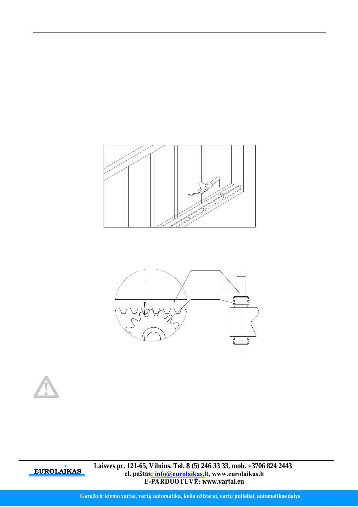
4.3.3 Gear rack installation
Fix the mounting screws to the rac .
Put the rac on the output gear, and weld the mounting screw to the gate (each screw with one
solder joints firstly).
Unloc the motor and can pull the gate smoothly.
Please chec whether there is a fit clearance between rac and output gear, as shown in Figure
7.
Weld all the mounting screws to the gate firmly.
Ma e sure that all rac s on the same straight line.
Pull the gate after installed, ma e sure the entire trip is flexible no stuc .
Figure 6
The fit clearance of output gear and rac is shown in Figure 7 below:
1-21-2
GearGear racrac
OutputOutput geargear
mmmm
Figure 7
Warnings
·To ensure safety, install safety stop bloc s on both ends of the rails to prevent the gate out of the rail.
Before installing the main engine, ma e sure that the safety stop bloc s are in place and whether it
has the function of preventing the gate from moving out of the rail and out of the safety range.
·Please ensure that the main engine and its components have good mechanical properties, and the
gate can operate flexibly when moved by hands before installing the main engine.
·In this product, one control can drive one main engine only, otherwise, the control system will be

EUROLAIKAS
Garažo ir kiemo vartai, vartųautomatika, kelio užtvarai, vartųpulteliai
, automatikos dalys
Laisvės pr. 121-65
, Vilnius. Tel. 8 (5) 246 33 33,
mob. +3706 824 2443
el. paštas: info@eurolaikas.lt, www.eurolaikas.lt
E-PARDUOTUVĖ: www.vartai.eu
8
damaged.
·Earth lea age circuit brea er must be installed where the gate movement can be seen, and the
minimum mounting height is 1.5m to protect it from being touched.
·After installation, please chec whether the mechanical property is good or not, whether gate
movement after manual unloc ing is flexible or not, and whether the infrared sensor (optional) is
installed correctly and effectively.
4.3.4 Limit switch adjustment
Spring limit switch - The installation site of spring limit switch is shown in Figure 8:
GateGate
SpringSpring limitlimit switchswitch
SpringSpring limitlimit switchswitch stopstop blocbloc
GearGear racrac
OutputOutput geargear
Figure 8
The installation of spring limit switch stop bloc is shown in Figure 9:
M6×10M6×10 M6×10M6×10
Figure 9

EUROLAIKAS
Garažo ir kiemo vartai, vartųautomatika, kelio užtvarai, vartųpulteliai
, automatikos dalys
Laisvės pr. 121-65
, Vilnius. Tel. 8 (5) 246 33 33,
mob. +3706 824 2443
el. paštas: info@eurolaikas.lt, www.eurolaikas.lt
E-PARDUOTUVĖ: www.vartai.eu
9
Magnetic limit switch - The installation site of magnetic limit switch is shown in Figure 10:
GateGate
MagnetsMagnets
MagneticMagnetic limitlimit switchswitch stopstop blocbloc
GearGear racrac
OutputOutput geargear
≤20mm
Figure 10
The installation of magnetic limit switch bloc is shown in Figure 11:
M6×18M6×18 M6×18M6×18
Left side mounting Right side mounting
Figure 11
Note: The default setting is right side mounting. (According to actual situation, please refer to the
“Note” of section 4.3.5.1 and 4.3.5.2 “Adjustment and operation” to adjust.)

EUROLAIKAS
Garažo ir kiemo vartai, vartųautomatika, kelio užtvarai, vartųpulteliai
, automatikos dalys
Laisvės pr. 121-65
, Vilnius. Tel. 8 (5) 246 33 33,
mob. +3706 824 2443
el. paštas: info@eurolaikas.lt, www.eurolaikas.lt
E-PARDUOTUVĖ: www.vartai.eu
10
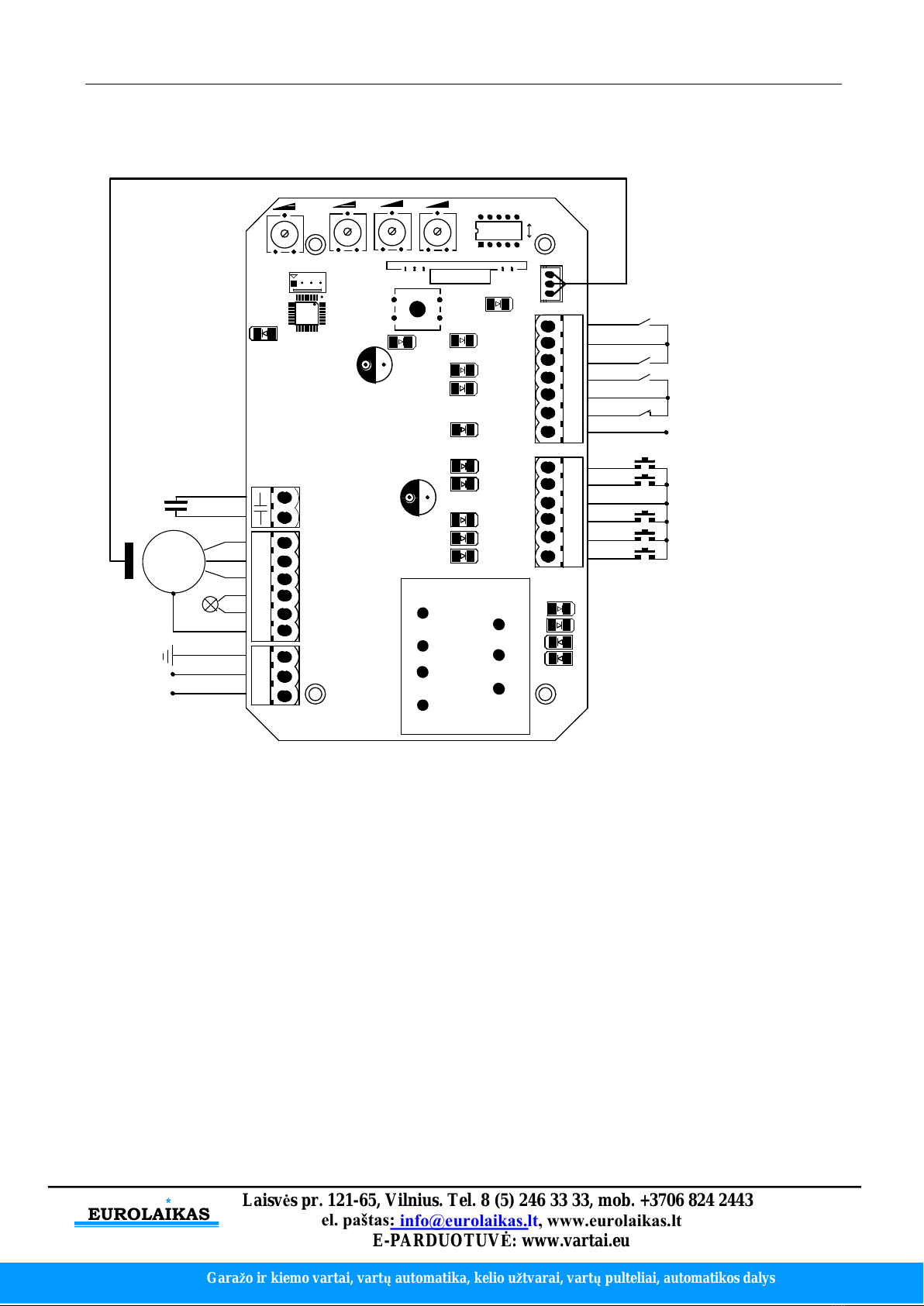
4.3.5 Control board wiring
4.3.5.1 Standard control board
+
+
O
+
24VDC24VDC
GNDGND
I.RI.R
CLLMCLLM
COMCOM
OPLMOPLM
COMCOM
STPSTP
X5X5
10A10A 250V250V
CLSCLS
OPNOPN
X1X1
W U V PEPE
D2D2 D1D1 C C
SW1SW1
ONON
AN1AN1
LED1LED1
X2X2X3X3
PEPE N L
X8X8
M
24VDC24VDC
GNDGND
PowerPower
LampLamp CapacitorCapacitor
InfraredInfrared sensorsensor
LimitLimit switchswitch
EarthEarth
LED2LED2
ExternalExternal buttonbutton
switchswitch
X7X7
MotorMotor
Figure 12
Wiring instruction:
1. Connect L and N to the power supply of AC220V/50HZ; AC110V/60HZ; L is live wire, N is
Neutral wire, and PE is grounding wire.
2. Connect LAMP to D1, D2; voltage: AC220V/50HZ; AC110V/60HZ.
3. Connect the motor wire U to the REV motor wire, connect W to the FWD motor wire, and
connect V to the motor common wire.
4. Connect C, C to the capacitor wire.
X5 Terminal
24VDC Power supply for fittings +24VDC
(
Electric current ≤50mA);
GND Power ground;
I.R Photocell input (N.C.);
CLLM Close limit switch;
COM Limit switch common terminal;
OPLM Open limit switch.
X7 Terminal
COM Control button common terminal;
STP Stop control button (N.O.);
CLS Gate close control button (N.O.);
OPN Gate open control button (N.O.).
EUROLAIKAS
Garažo ir kiemo vartai, vartųautomatika, kelio užtvarai, vartųpulteliai
, automatikos dalys
Laisvės pr. 121-65
, Vilnius. Tel. 8 (5) 246 33 33,
mob. +3706 824 2443
el. paštas: info@eurolaikas.lt, www.eurolaikas.lt
E-PARDUOTUVĖ: www.vartai.eu
11
DIP Switch
1. External button switch. ON - Three button switch; OFF - One button switch (X7 terminal CLS
button can be used to circularly control the main engine OPEN/STOP/CLOSE/STOP).
2. Automatic close time.
3. Automatic close time.
2 ON 3 OFF: automatic close time is 15s,
2 OFF 3 ON: automatic close time is 30s,
2 OFF 3 OFF: automatic close time is 45s,
2 ON 3 ON: no automatic close function.
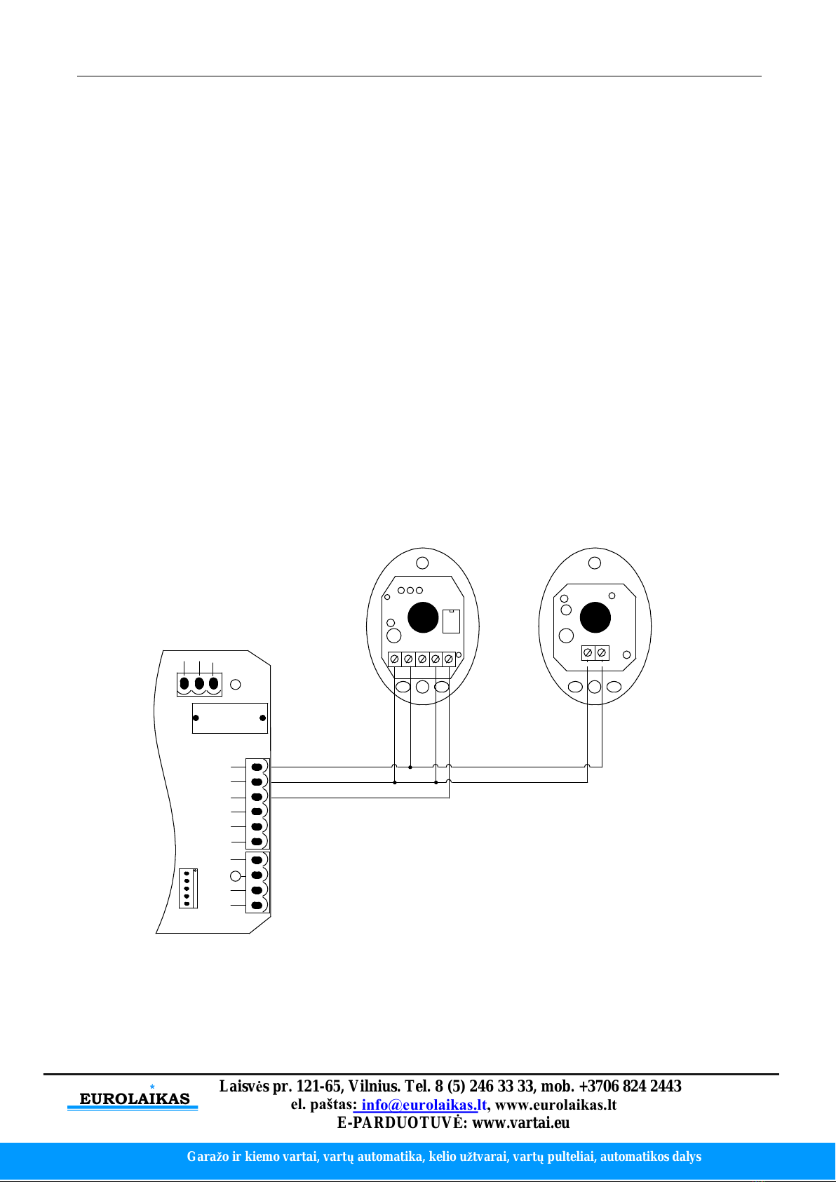
Infrared connection
Infrared photocell function: In the closing process, when infrared ray of the photocell is covered by
people or objects during its detection range, the gate will open immediately for security protection.
The distance between photocell receiver and photocell emitter should be more than 2 meters,
otherwise will affect the induction of the photocell.
If connect the infrared photocell, please remove the short connection between I.R and GND on the
X5 terminal.
24VDC24VDC
GNDGND
I.RI.R
CLLMCLLM
COMCOM
OPLMOPLM
COMCOM
STPSTP
X5X5
10A10A 250V250V
CLSCLS
OPNOPN
X1X1
PEPE N L
X8X8
X7X7
V+
V-
V+V- NO COM NC
InfraredInfrared receiverreceiver connectingconnecting InfraredInfrared emitteremitter connectingconnecting
Figure 13

EUROLAIKAS
Garažo ir kiemo vartai, vartųautomatika, kelio užtvarai, vartųpulteliai
, automatikos dalys
Laisvės pr. 121-65
, Vilnius. Tel. 8 (5) 246 33 33,
mob. +3706 824 2443
el. paštas: info@eurolaikas.lt, www.eurolaikas.lt
E-PARDUOTUVĖ: www.vartai.eu
12
Adjustment and operation
Remote control operation
Three button mode remote control: OPEN/CLOSE/STOP of main engine are controlled by three
buttons separately on the remote control.
Single button mode remote control: OPEN/CLOSE/STOP of main engine are controlled by one
button circularly on the remote control.
ThreeThree buttonbutton modemode remoteremote controlcontrol SingleSingle buttonbutton modemode remoteremote controlcontrol
A
B
C
D
OPENOPEN
A
B
C
D
CLOSECLOSE
STOPSTOP
CLOSECLOSE
OPENOPEN
STOPSTOP
Figure 14
Add extra remote control remote control learning): Remove the main engine housing, then ta e
out the upper cover of the control box, press the learning button AN1 on the control board, and
indicator light LED2 will flash. Press the button that to be learned on the remote control once, The
LED2 will be off. Press the same button on the remote control twice, the LED2 will flash several
times and be off; remote control learning complete. A maximum of 25 remote controls can be
learned.
Delete remote control: To delete remote control that have been learned: press and hold the
learning button AN1, the indicator light LED2 will be on; Then release it until LED2 is off. After the
steps, all the matched remote controls will be deleted.
Note: To disengage gate opener, move the gate to the middle position, then close the clutch and
press the open button of external button switch to open the gate. If the gate opening direction is
wrong, you can change the direction through the toggle switch SW1 on the control board or
exchange the motor phase-sequence lines U and W. If the opening or closing limit is wrong,
please exchange limit switch lines LLM and OPLM on the control board.
EUROLAIKAS
Garažo ir kiemo vartai, vartųautomatika, kelio užtvarai, vartųpulteliai
, automatikos dalys
Laisvės pr. 121-65
, Vilnius. Tel. 8 (5) 246 33 33,
mob. +3706 824 2443
el. paštas: info@eurolaikas.lt, www.eurolaikas.lt
E-PARDUOTUVĖ: www.vartai.eu
13
4.3.5.1 Intelligent control board
L
PEPE
1313
LAMPLAMP
PEPE
32
1456791010 1111 1212
8
MOTMOT
MOTMOT
COMCOM
MOT1MOT1
MOT2MOT2
CAPCAP
SPEEDSPEED GNDGND VCCVCC
N
L N
OFFOFF
ONON
X1X1
J5J5
U1U1
HALLHALL
J2J2
U2U2
S1S1
VR3VR3 VR4VR4
LEARNLEARN
POWERPOWER
J1J1
J6J6
J3J3
1313
1111
5 6
VR1VR1 VR2VR2
81010
SW1SW1
123
J4J4
12VDC12VDC
GNDGND
LimitLimit switchswitch
LoopLoop detetcordetetcor
O/S/CO/S/C switchswitch
ExternalExternal buttonbutton
PedestrianPedestrian switchswitch
M
PowerPower
EarthEarth
CapacitorCapacitor
LampLamp
HallHall lineline
InfraredInfrared sensorsensor
switchswitch
Figure 15
Wiring instruction:
1. Connect L and N to the power supply of AC220V/50HZ; AC110V/60HZ; L is live wire, N is
Neutral wire, and PE is grounding wire.
2. Connect LAMP to caution light; voltage: AC220V/50HZ; AC110V/60HZ.
3. Connect the motor wire MOT2 to the REV motor wire, connect MOT1 to the FWD motor wire,
and connect MOTCOM to the motor common wire.
4. Connect MOTCAP to the capacitor wire.
J2 (For the convenience of wiring, this terminal is accompanied with failure diagnosis light)
1. Gate close control button (N.O.)
2. Gate open control button (N.O.)
3. Stop control button (N.O.)
4. Control button common terminal
5. Open/Stop/Close/Stop loop control button (N.O.)
6. Pedestrian mode control button (N.O.)

EUROLAIKAS
Garažo ir kiemo vartai, vartųautomatika, kelio užtvarai, vartųpulteliai
, automatikos dalys
Laisvės pr. 121-65
, Vilnius. Tel. 8 (5) 246 33 33,
mob. +3706 824 2443
el. paštas: info@eurolaikas.lt, www.eurolaikas.lt
E-PARDUOTUVĖ: www.vartai.eu
14
J5 (For the convenience of wiring, this terminal is accompanied with failure diagnosis light)
7. Power supply for fittings: +12V
(
Electric current ≤100mA)
8. Photocell input (N.C.); short out the device if not used.
9. GND
10. Loop detector (sensor coil) connector (N.O.)
In the closing process, once vehicles are detected by the loop detector, the gate will open
soon; when the vehicle passes, the gate will close automatically. When the gate is in a
halted state, it will eep this state when vehicles are detected; after the vehicle passes, the
gate will close automatically.
In the above loop detector function, users can ma e the gate close automatically 12
seconds later after the vehicle passes. Change the No.4 ey of the dip switch on circuit
board, and the gate will close automatically 12 seconds later after the vehicle passes.
11. Close limit switch
12. Limit switch and other input signal common terminal
13. Open limit switch
Function adjustment
Functional parameters of the control board equipped with microprocessor can be adjusted through
potentiometer and dip switch, so as to meet different installation requirements.
1313
1212
SPEEDSPEED GNDGND VCCVCC
OFFOFF
ONON
X1X1
HALLHALL
U2U2
S1S1
VR3VR3 VR4VR4
LEARNLEARN
POWERPOWER
J1J1
1313
VR1VR1 VR2VR2
SW1SW1
1 2 3 4 5
Figure 16
Adjusting knob
VR1: When meet obstacle reverse function is enabled (DIP switch 5 at OFF position and the motor
assembled the hall line). This nob is used for sensitivity adjustment of meet obstacle.
Cloc wise rotation to reduce sensitivity of obstacle, counter-cloc wise rotation to increase sensitivity
of obstacle.
When meet obstacle reverse function is disabled (DIP switch 5 at ON position). This nob is used for
motor wor ing total time adjustment. Cloc wise rotation to increase, counter-cloc wise rotation to
reduce. The total time can be set to 10 seconds as minimum and 90 seconds as maximum.
VR2: For bra e force adjustment in limit position.
Cloc wise rotation to increase, counter-cloc wise rotation to reduce.
Rotate to minimum to cancel bra e function in place.
VR3: For slow stop width adjustment.
Cloc wise rotation to increase, counter-cloc wise rotation to reduce.

EUROLAIKAS
Garažo ir kiemo vartai, vartųautomatika, kelio užtvarai, vartųpulteliai
, automatikos dalys
Laisvės pr. 121-65
, Vilnius. Tel. 8 (5) 246 33 33,
mob. +3706 824 2443
el. paštas: info@eurolaikas.lt, www.eurolaikas.lt
E-PARDUOTUVĖ: www.vartai.eu
15
VR4: For motor output force adjustment to eep safe usage.
Cloc wise rotation to increase, counter-cloc wise rotation to reduce.
Note: the default setting is VR1, VR2, VR3, VR4 are the maximum value, and the user can adjust
according to the actual requirement.
Warning: the motor output force cannot set too large, just to be able to drive the gate.
Dip switch
1. Soft start function. OFF - enabled; ON - disabled.
2. Limit switch setting. OFF- normal open (N.O.); ON - normal close (N.C.).
3. Automatic close time.
4. Automatic close time.
Setting for automatic close time:
3 OFF 4 ON: automatic close time is 12s,
3 ON 4 OFF: automatic close time is 24s,
3 ON 4 ON: automatic close time is 36s,
3 OFF 4 OFF: no automatic close function.
5. Meet obstacle reversal function. OFF - enabled; ON - disabled.
Infrared connection
Infrared photocell function: In the closing process, when infrared ray of the photocell is covered by
people or objects during its detection range, the gate will open immediately for security protection.
The distance between photocell receiver and photocell emitter should be more than 2 meters,
otherwise will affect the induction of the photocell.
If connect the infrared sensor, please remove the short connection between 8 and 9 on the J5
terminal
1313
791010 1111 1212
8
SPEEDSPEED GNDGND VCCVCC
OFFOFF
ONON
X1X1
J5J5
U1U1
HALLHALL
U2U2
S1S1
VR3VR3 VR4VR4
LEARNLEARN
POWERPOWER
J1J1
1313
1111
VR1VR1 VR2VR2
81010
SW1SW1
V+V-
V+
V- NO COM NC
InfraredInfrared receiverreceiver connectingconnecting InfraredInfrared emitteremitter connectingconnecting
Figure 17

EUROLAIKAS
Garažo ir kiemo vartai, vartųautomatika, kelio užtvarai, vartųpulteliai
, automatikos dalys
Laisvės pr. 121-65
, Vilnius. Tel. 8 (5) 246 33 33,
mob. +3706 824 2443
el. paštas: info@eurolaikas.lt, www.eurolaikas.lt
E-PARDUOTUVĖ: www.vartai.eu
16
Adjustment and operation
Remote control operation
Three button mode remote control: OPEN/CLOSE/STOP of main engine are controlled by three
buttons separately on the remote control.
Single button mode remote control: OPEN/CLOSE/STOP of main engine are controlled by one
button circularly on the remote control.
ThreeThree buttonbutton modemode remoteremote controlcontrol SingleSingle buttonbutton remoteremote controlcontrol
A
B
C
D
OPENOPEN
A
B
C
D
CLOSECLOSE
STOPSTOP
CLOSECLOSE
OPENOPEN
STOPSTOP
PedestrianPedestrian modemode PedestrianPedestrian modemode
Figure 18
Add extra remote control remote control learning): Remove the main engine housing, then ta e
out the upper cover of the control box, press and hold the learning button S1 for 2 seconds, then the
indicator light LEARN will be on; press the button that to be learned on the remote control twice, the
LEARN will flash several times and be off; remote control learning complete. A maximum of 40
remote controls can be learned.
Delete remote control: To delete remote control that have been learned; press and hold the
learning button S1, the indicator light LEARN will be on; Then release it until LEARN is off. After the
steps, all the matched remote controls will be deleted.
The fourth button on the remote control is for pedestrian mode, press the button while the door is
closed, it will open for 1 meter which is for pedestrian only.
Note: To disengage gate opener, move the gate to the middle position, then close the clutch and
press the open button of external button switch to open the gate. If the gate opening direction is
wrong, you can exchange the motor phase-sequence lines MOT2 and MOT1. If the opening or
closing limit is wrong, please exchange limit switch lines which are connected to the
corresponding terminal 11 and 13 on the control board.
5. Others
5.1 Maintenance
Chec whether the gate operates normally every month.
For the sa e of safety, each gate is suggested to be equipped with infrared protector, and regular
inspection is required.
Before installation and operation of the gate opener, please read all instructions carefully.

EUROLAIKAS
Garažo ir kiemo vartai, vartųautomatika, kelio užtvarai, vartųpulteliai
, automatikos dalys
Laisvės pr. 121-65
, Vilnius. Tel. 8 (5) 246 33 33,
mob. +3706 824 2443
el. paštas: info@eurolaikas.lt, www.eurolaikas.lt
E-PARDUOTUVĖ: www.vartai.eu
17
Our company has the right to change the instruction without prior notice.
5.2 Troubleshooting
Problems Possible Reasons Solutions
The gate cannot open or
close normally, and LED
does not light.
1.The power is off.
2.Fuse is burned.
3.Control board power wiring with
problem.
1.Switch on the power supply.
2.Chec the fuse (code FU),
change the fuse if burnt.
3.Re wiring according to
instructions.
The gate can open but
cannot close.
1.Photocell wiring with problem.
2.Photocell mounting with problem.
3.Photocell is bloc ed by objects.
4.Sensitivity of obstacle is too high
(Intelligent type).
5.Hall switch parts is damaged
(Intelligent type).
1.If not connect photocell,
please ma e sure that the
infrared port and GND short
circuit; if connect infrared
sensor, please ma e sure the
wiring is correct and the
photocell is N.C.
2.Ma e sure that the photocell
mounting position can be
mutually aligned.
3.Remove the obstacle.
4.Reduce the sensitivity of
obstacle.
5.Change hall switch parts.
Remote control doesn’t
wor .
1.Battery level of the remote
control is low.
2.Remote control learning is not
completed.
1.Change the remote control
battery.
2.Re-conduct remote control
learning.
Press OPEN, CLOSE
button, the gate is not
moving, motor has
noise.
1.Capacitor is bro en.
2.Capacitor is poor connected.
3.Gate moving is not smoothly.
1.Change capacitor.
2.Chec the capacitor wiring.
3.According to the actual
situation to adjust the motor or
the gate.
Not stop at the limit
position when opening /
closing.
1. The limit direction is wrong.
2. The mounting of magnetic limit
switch with problem.
1.Chec whether the limit
switch wiring is consistent with
the actual direction of
operation.
2. Chec whether the distance
between magnetic limit switch
and motor, and the height of
the magnetic limit switch can
reach up the mounting
requirement.

EUROLAIKAS
Garažo ir kiemo vartai, vartųautomatika, kelio užtvarai, vartųpulteliai
, automatikos dalys
Laisvės pr. 121-65
, Vilnius. Tel. 8 (5) 246 33 33,
mob. +3706 824 2443
el. paštas: info@eurolaikas.lt, www.eurolaikas.lt
E-PARDUOTUVĖ: www.vartai.eu
18
Lea age switch tripped. Power supply line short circuit or
motor line short circuit. Chec wiring.
Remote control wor ing
distance is too short. Signal is bloc ed.
Connect external receiver
antenna, 1.5 meters above
ground.
The gate moves to the
middle position to stop
or reverse.
1.Motor output force is not enough
(Intelligent type).
2.Sensitivity of obstacle is too
big(Intelligent type).
3.Gate meets obstacle.
1.Adjust the VR4.
2.Adjust the VR1.
3.Remove the obstacle.
This manual suits for next models
3
Table of contents
Other EUROLAIKAS Gate Opener manuals


