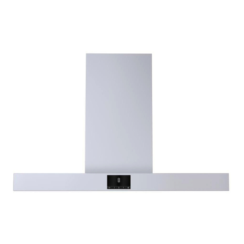
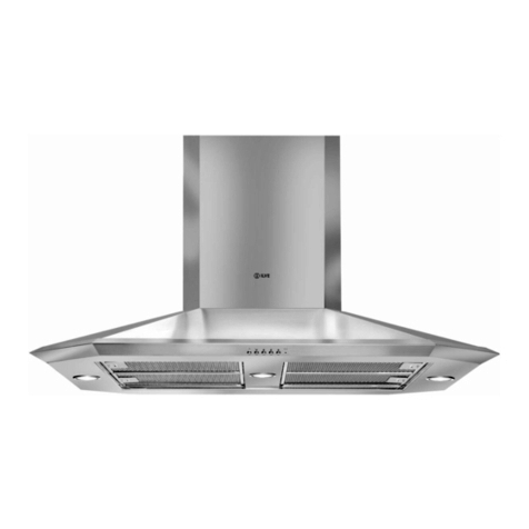
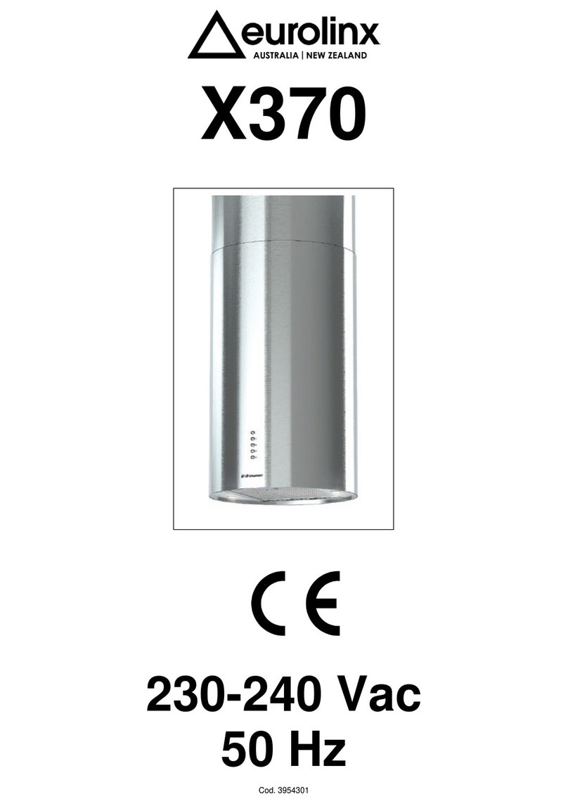
Eurolinx X370 User manual

X370
230Vac - 50Hz


Exhausting cooker hood. The equipment is constructed in
accordance with European Standards and with the requirements
included in the following Directives: 2006/95EC ( Low Voltage
Directive), 2004/108 (Electromagnetic Compatibility).
1 INSTALLATION
The equipment (Picture 1 ) is made of the following items :
1. Telescopic inside structure (Picture 1-1)
2. Telescopic external chimney (Picture 1-2)
3. Cooker hood module (Picture 1-3)
4. Filter support bracket ( Picture 1-4).
Read the instruction manual before installing and/or
using the hood.
The unit must be tted at a distance of at least 65 cm.
from the cooking hob. It must not be mounted above
cookers tted with top radiant plate. The stale air must
be discharged in a manner complying with current
regulations.
If the mounting instructions of the gas cooker indicate a
wider distance, respect it. The unit must not be mounted
above cookers.
The hood is equipped with all the necessary fastenings
for its installation, which are suitable for most surfaces.
Anyway, ask to a professional to verify that the
installation surface is strong enough. Installation must
be carried out by qualifed installers according to present
regulations. For an easy access, it is advisable to
move possible furniture under the installation area. All
fastenings are supplied.
INSTALLATION OF THE STRUCTURE TO THE CEILING
(Picture 2)
Uninstall the hood as shown in the sequences 3A, 3B
(also disconnect the spotlights and controls connections),
3C, 3D
Adjust the height (A) of the structure of the hood making
a difference between the ceiling and the 65 cm of the
cooking surface, bearing in mind that the suction surface
stick out 2 cm from quota A
DIRECT FASTENING TO THE CEILING
Fasten the hood with the plugs supplied (pic.5)
Install the duct out pipe (pic.6)
Connect the unit electrically
Reinstall the hood by following steps 3 (A, B, C, D) in
reverse order as per (pic.7)
FASTENING WITH FALSE CEILING
Fasten the hood with the plugs supplied (pic.5)
Install the duct out pipe (pic.8)
Connect the chimney fastening brackets A to the hood,
bearing in mind that the false ceiling can be from 170 to
250 mm far from the ceiling
Connect the duct out pipe till the drain
Connect the unit electrically
Install the false ceiling as shown in (pic. 9)
Reinstall the hood by following steps 3 (A, B, C, D) in
reverse order as per (pic.7)
2 ELECTRICAL CONNECTION
This equipment must be connected to a grounding plant.
Two types of electrical connection can be used:
a) Using a standard plug to be connected to the
power cable and inserted in a mains socket which must
be accessible (so that the plug can be disconnected
when servicing is carried out).
b) By means of a xed mains connection, tting a
bipolar switch with contacts opening of at least 3 mm. The
ground connection (yellow-green wire) must not be inter-
rupted. Refer to the plate inside the hood for the mains
voltage and frequency ratings.
3 USE
This cooker hood can be employed as exhausting.
Kitchensmokesaredrivenoutsidethroughauejoinedto
theexhaustpipeueconnector(Picture4).
Install this ue after completing what described in the
previous point 2 of paragraph INSTALLATION.
This pipe must not under any circumstances be connected
to cooker, boiler or burner exhaust pipes, etc.
If the hood is operated in suction function whilst stoves, gas
cookers, fuel-fed boilers. etc. are being used, ventilation
from outdoors must be provided, since the cooker hood
removes from the environment the necessary air for a
correct combustion.
4 OPERATION
The hood is supplied with a multi speed motor. The hood
should be run at low speed under normal conditions and
at higher speeds only when there is a heavy build-up of
fumes or odours. Ideally, the hood should be switched on
when starting cooking and kept on until all odours have
been eliminated. The controls are provided with buttons
(see drawing below) for switching on the light TL, for
switching on the motor and selecting the operating speed
T1-T2-T3-T4.
BytherstpressureofthecommandT1themotorstarts
running at the 1st speed; by the second pressure the
motor gets off at any planned speed. The commands T2-
T3-T4 switch the motor respectively at the 2nd, 3rd and
4th speed. Press T1 for switching it off. With the button T4,
select the maximum speed of the extraction fan for 5 minutes
(LED blinking), after which the extraction fan will automatically
switch to the 3rd speed.
SELF SWITCHING OFF : Turn on the cooker hood at the
wanted speed in order to activate the self-switching off,
then keep pressed the button “TL” for a few seconds, until
all the LED start blinking. Pressing one of the buttons (T1,
T2, T3, T4) it is possible to program the self-switching off
time, which is different according to the pressed button
T1= 5 minutes
T2=10 minutes
T3=15 minutes
T4=20 minutes
When the option of the self switching off time corresponds
to the speed previously programmed the speed LED
blinks;whentheoptionisdifferentthespeedledisxed.
INSTALLATION, OPERATING AND MAINTENANCE INSTRUCTIONS FOR COOKER HOODS
MODEL X370 230 Vac - 50 Hz

FILTER TIMER : After the cooker hood has worked for
30 hours, once it is turned off all the LED switch on with
axedlightfor30secondsinordertoadvisethattheal-
uminium lters need to be cleaned. If pressed for some
seconds the button “T1+T4” will reset the timer. In case
this button is not pressed the same operation will occur
again after the cooker hood has been switched off. This
operation will occur every 30 hours, till achievement of
120 hour functioning. Once the cooker hood has worked
for 120 hours and it is turned off, all the LED switch on
with a blinking light for the following 30 seconds to remind
thecleaningofthealuminiumltersandthereplacement
ofthecharcoallters,incasethecookerhoodisltering.
Once the timer has been reset all the same process will
occur after the next 30 hour exhausting.
5 MAINTENANCE
Always disconnect the hood from the mains before
carrying out any maintenance or cleaning operation.
Particular attention should be paid to the metallic fat-
retaining lters that are designed to trap particles of fat
contained in the fumes. The metallic fat-retaining lters
must be washed at least once a month with detergent in
hot water (or in the dish-washer).
In order to remove the anti-grease lters, follow what
describedinPicture3-P.Replacetheltersonlyoncethey
are completely dry.
ATTENTION: the grease collected in the lters can
easily catch re and it is therefore extremely important
to clean the metallic lters on a regular basis as per
instructions.
Once the hood is switched off, after 120 hour functioning,
all LEDS blink for 30 seconds to remind that the charcoal
lter needs cleaning. To set the timer to zero keep the
button T1 pressed with the aspirator switched off, otherwise
the timer will remain set on 120 hour functioning and the
reminder will occur again when the hood is switched off
again.
The hood features a LED light that, in addition to offering
a good lighting and a signicant energy savings, is
guaranteed to last on average 10 times more than
traditional lights. For replacement, contact the Assistance
Service.
6 WARNINGS
We remind that the use of products functioning with
electrical energy implies the observance of some essential
security rules, as follows:
• Children and not assisted disabled people are not
admitted to use the cooker hood.
• Any cleaning action is forbidden if the appliance hasn’t
been disconnected from the main power supply and
if the main switch of the house electrical system is not
off. The exterior of the cooker hood must be cleaned
using a soft, damp and neutral detergent. Do not use
solvents, patrol-based or abrasive substances.
• Do not pull, take off or twist the cable coming out from
the appliance, even though this has been disconnected
from the main power supply.
• Do not sprinkle or throw any water directly on the
appliance.
• Do not stick any sharp tool inside the exhausting holes
and into the air discharge.
• Donottakeouttheltersinordertoreachtheinternal
sides of the appliance in case the main switch of the
house electrical system is not off.
• Donotsingeorambédirectlyunderneaththecooker
hood. Take particular care when frying to ensure that
theoildoesnotcatchre.
• The present instruction manual is an integral part of
the appliance itself, therefore it must be carefully
kept and always accompany it, even in case of its
assignment to another owner or user or in case the
cooker hood is moved to another installation plant.
• Any eventual adjustment to the electrical system,
which may be necessary to install the cooker hood,
must be carried out only by competent people. Any
repair carried out by no competent people may cause
damages. For any repair or needed technical action
make reference to a Technical Assistance Center,
whichis authorized tocarry out thereplacement of
the spare parts.
• Always make sure that all the electrical parts (lights,
exhaustion unit) are disconnected when the appliance
is not in use.
• By storms take off the main switch of the house
electrical system.
• The using of the cooker hood must not be other than
the use of exhausting units for cooking damps on
domestic kitchens. The manufacturer does not accept
any liability for damages caused by people, animals or
things, by installation and maintenance mistakes or by
any illegitimate use.
• Makesurethatthevoltage(V)andthefrequency(Hz)
ratings indicated on the plate inside the cooker hood
correspond to the ones available in the installation
place.
0-1 2 3 4
TL T1 T2 T3 T4

1-2
1-1
1-3
1-4
min. 650mm
3A
3B
3C
3D
Pct.1 Pct. 2
Pct. 3

A
760 ÷ 1170
Pct. 4 Pct. 5
Pct. 6 Pct. 7

8A
8A
1000 ÷ 1280
170 ÷ 250
Pct. 8 Pct. 9

COD. 395.430
NOTES
Table of contents
Other Eurolinx Ventilation Hood manuals
Eurolinx
Eurolinx X301ISL User manual
Eurolinx
Eurolinx I-HOOD Assembly instructions
Eurolinx
Eurolinx X370 User manual
Eurolinx
Eurolinx CH900X User manual

Eurolinx
Eurolinx IVCU90 User manual
Eurolinx
Eurolinx X400/80 User manual
Eurolinx
Eurolinx IVCU60 Assembly instructions

Eurolinx
Eurolinx HU80 User manual
Eurolinx
Eurolinx CLN 90/MX User manual
Eurolinx
Eurolinx CHR1000W User manual


