3
Genesis CD–2G, CD–5G, & CD–7G Installation & Operations Manual
SECTION 3 Operation
3A. Initial System Start-Up
Upon completing all of the generator system
connections, you are ready to begin start-up
procedures.
1. Check electrical fittings.
2. Check for proper voltage.
3. Turn on circulation pump.
4. Check for leaks.
5. With the ozone isolation valve closed, adjust
injector bypass valve and/or filtration sidestream
valve to flow water through the injector.
6. Open ozone isolation valve.
7. Turn ozone generator on.
NOTE: If your Injector Assembly is equipped
with a ball valve, close the valve by turning
the handle clockwise until the proper suction
is indicated as described in Section 3B.
3B. Normal Operation
At this point, the system's cooling fans will
start-up and the oxygen concentrator will begin
operating. The green power indicator should
be illuminated and the red vacuum indicator
should turn off when sufficient vacuum is
obtained. The green ozone indicator should
then illuminate.
If the indicator lights are OK and the flowmeter is
reading the proper flow (refer to specification label
in unit), then the ozone generator is producing
ozone and the injector assembly is injecting the
ozone into the pool return/inlet line.
Make further adjustments to the injector bypass
valve until vacuum light turns off and the ozone
light turns on. NOTE: Do not exceed the max air/
oxygen flow rate specification as indicated on
the specification sticker.
If you experience complications, see
TROUBLESHOOTING Section 4C or call
1-800-676-1335 for assistance.
3C. System Shut-Down
The following sequence of steps must be followed
for servicing or for storage.
1. Unplug the ozone generator.
2. Close the ozone isolation valve on the ozone
supply line.
WARNING: Pool pump flow must not be shut-
down when the ozone generator is operating.
Doing so may cause water to back flow into the
system and damage the generator module.
SECTION 4 Maintenance & Service
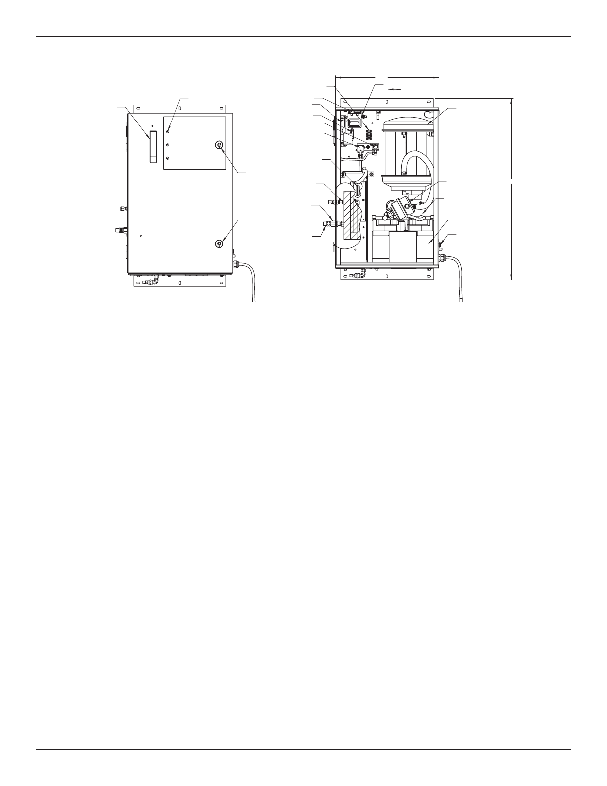
4A. System Electro-Mechanical Overview
Refer to Figure 4 for component locations.
4A-1. Indicator Lights
1. Main Power: Green light indicates that power
is being supplied to the ozone generator.
Compressor should be running.
2. Ozone Power: Green light indicates that power
is being supplied to the high voltage Corona
Discharge circuit and that ozone is being
produced.
3. Vacuum: Red light indicates a vacuum fault.
When sufficient suction is being supplied from
the venturi injector, the red light will turn off.
4A-2. Internal Components
1. Corona Discharge (CD) Module: The generator
module consists of a high voltage electrode
wrapped around a Teflon core inserted in a
ceramic insulating tube. The assembly is
encased in a thermally protected aluminum
heat sink.
2. Power Supply: The fuse protected, self-
regulated, high voltage/high frequency power
supply provides the ideal electrical signal for
efficient ozone production.
3. Air Compressor: Compressor produces and
supplies compressed air to oxygen concentrator.
4. Oxygen Concentrator: Supplies concentrated,
dry, oxygen feed gas to the ozone generator.
5. Lo Limit Vacuum Switch: If the vacuum in the
ozone output supply line falls below 2 in. Hg the
switch will open causing the system to shut-down.
6. Ventilation Fan: Cooling fan operates whenever
the ozone generator is plugged in.
7. Intake Screens: Easily removable screens keep
debris from entering the enclosure. See Figure 3.