Euroretracts Professional RCA/15946/000 User manual

ITALIANO
ENGLISHFRANCAIS
DEUTSCH
RCA/15946/000
RCA/15947/000
Kits distribuzione ad olio - Oil distribution kits
Boîte de distribution huile - Ölversorgungskit
Professional Line
Istruzioni per l’installazione - Installation instructions
Montage - Einbaueinleitung

ITALIANO
AVVERTENZE E PRECAUZIONI
Questi carrelli devono essere utilizzati da persone esperte nel
settore del modellismo aereo.
E’ sconsigliato l’utilizzo ai minori di anni 12 se non seguiti
da un adulto.
L’impianto di questi carrelli una volta caricato contiene olio
od aria compressa ad alta pressione, evitate di staccare la
tubazione quando l’impianto è in pressione.
Questi carrelli devono essere utilizzati esclusivamente per
aeromodelli.
Allontanate qualsiasi parte del corpo e non trattenete le gambe
dei carrelli durante il funzionamento.
Non caricate i serbatoi di aria compressa ad una pressione
maggiore di 10 bar.
Evitate di far funzionare i carrelli ad una pressione bassa
poiché la retrazione non avverrà correttamente.
Non utilizzate questi carrelli in caso di danneggiamento di
qualche parte o perdite dell’impianto, prima di aver eseguito
le riparazioni del caso.
In caso di inosservanza delle seguenti norme sono possibili
danni a persone o cattivi funzionamenti dei carrelli.
La ditta Euroretracts vi ringrazia per la preferenza accordata
ai suoi prodotti e vi consiglia di seguire attentamente le avver-
tenze e le istruzioni riportate in questo manuale per un buon
utilizzo di questi carrelli.

ITALIANO
troppo presto lasciando i carrelli parzialmente aperti o chiusi.
I tempi regolari di apertura o chiusura sono di circa 10-20 secondi, comunque la centralina è tarata
anche per staccare la pompa dopo circa 45 secondi, questo per evitare di scaricare completamente
la batteria.
Con un pacco batteria da 1800 mAh è possibile effettuare circa 8-10 aperture-chiusure. Vi
raccomandiamo di fare attenzione che la batteria sia sempre ben carica per evitare malfunzionamenti
del circuito.
Per completare il riempimento iniziale del circuito, è necessario azionare varie volte l’impianto dei
carrelli in apertura e chiusura per permettere l’uscita totale dell’aria dalle tubazioni e dai cilindri;
il nostro circuito non ha bisogno di valvole di sfogo per l’aria, poiché la stessa, durante i cicli
di apertura e chiusura iniziali viene inviata all’interno del serbatoio dell’olio dove rimarrà senza
provocare inconvenienti.
Se durante la fase iniziale di riempimento del circuito il livello dell’olio nel serbatoio si abbassa
troppo è necessario rabboccare il livello per evitare che il pendolo aspiri aria invece che olio.
Se ben realizzato e se non ci sono perdite il circuito idraulico non ha bisogno di alcuna manutenzione,
è sufciente controllare che il livello di olio nel serbatoio (dopo aver riempito tutto il circuito)
rimanga all’incirca a metà. Prima di ogni volo vi consigliamo di controllare il buon funzionamento
dell’impianto effettuando un ciclo di apertura/chiusura.
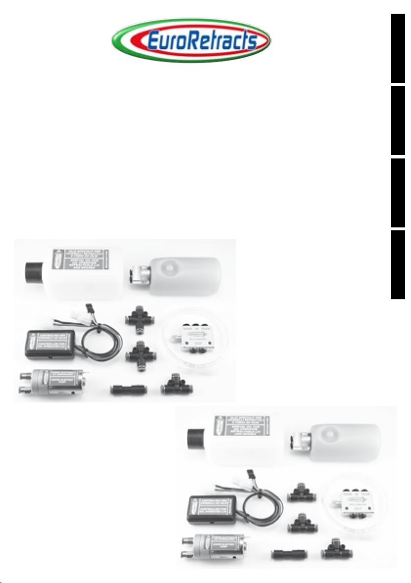
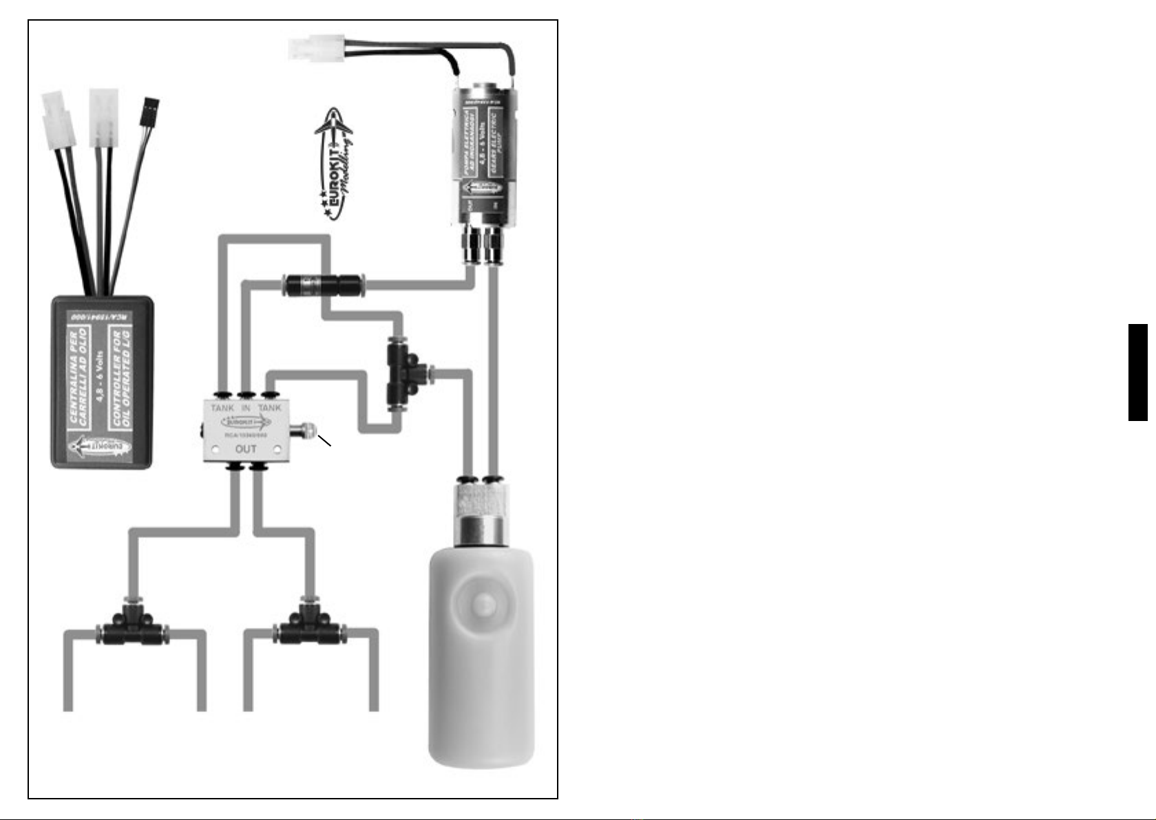
INSTALLAZIONE CARRELLI AD OLIO
Dopo aver ssato i carrelli al modello, posizionate e ssate in fusoliera i seguenti componenti:
• distributore olio e relativo servocomando collegandoli fra loro con un’asta e una forcella
di acciaio.
• serbatoio olio, ssandolo con elastici di caucciù o fascette di nylon al supporto ricavato
nella fusoliera, ponendo fra il supporto e il serbatoio un rettangolo di gommaspugna per
ammortizzare le vibrazioni.
• pompa elettrica ad ingranaggi, ssandola al supporto ricavato nella fusoliera con fascette
metalliche o di nylon, ponendo fra il supporto e la pompa un rettangolo di gommaspugna per
ammortizzare le vibrazioni.
• centralina di comando, inserire in un tubo di gommaspugna e ssare al supporto in fusoliera
con elastici di caucciù.
• pacco batterie da 4,8 - 6 Volts 1800 mAh art. RCA/15945/000, idem come la centralina
di comando.
• i connettori a T e a croce possono essere ssati al modello o lasciati volanti.
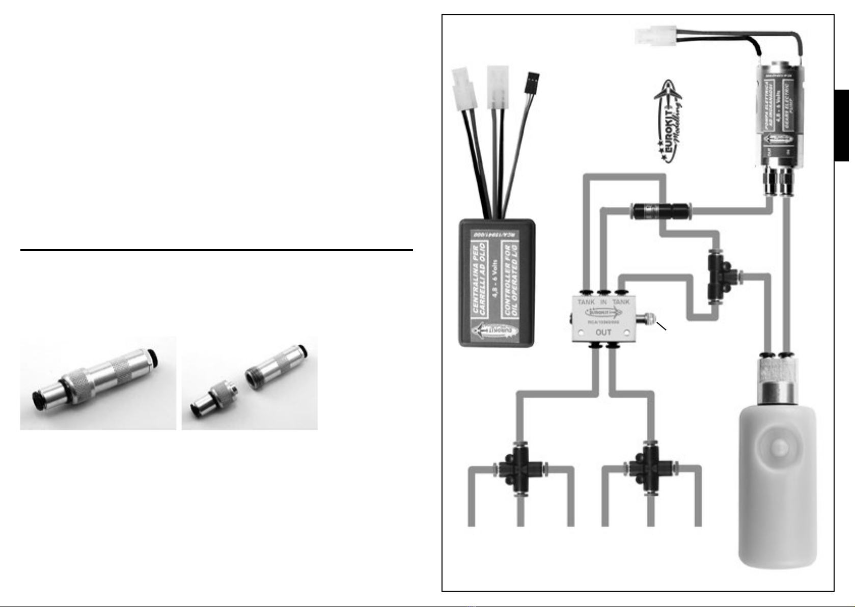
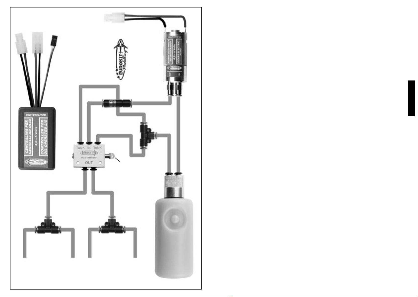
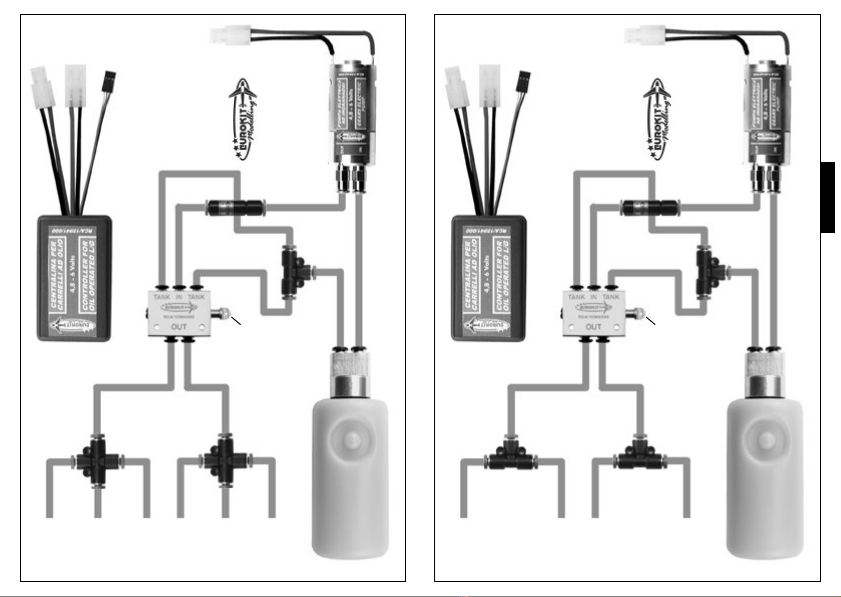
Collegare tutta la tubazione dopo averla tagliata a misura, seguendo gli schemi riportati in questo
libretto per le terne o coppie di carrelli retrattili ad olio, fate attenzione a non collegare invertiti
la valvola unidirezionale o i tubi della pompa e del serbatoio altrimenti il circuito non funzionerà
correttamente.
Per quanto riguarda l’innesto dei tubi nei vari dispositivi e raccordi, è sufciente premere con
forza il tubo nel rispettivo attacco rapido no a quando tocca il fondo dell’attacco stesso, a questo
punto il tubo viene bloccato dalla molla interna. Per staccare il tubo basta premere l’anello esterno
di plastica o di metallo verso il corpo dell’attacco rapido allentando così la molla interna, e tirare
il tubo che si slerà dall’attacco.
Staccare dal connettore a T il tubo di ritorno serbatoio olio e dal connettore “IN” della pompa il
tubo che la collega al pendolo del serbatoio; riempire attraverso questo tubo il serbatoio stesso
con circa 100-110 cc. di olio speciale per circuiti idraulici, fornito insieme al kit, l’aria contenuta
all’interno del serbatoio uscirà attraverso il tubo di ritorno serbatoio olio. Inserire nuovamente i
due tubi nella T e nella pompa, facendo attenzione a non invertirli.
Collegate il connettore elettrico della pompa e la batteria da 4,8-6 Volts ai rispettivi connettori
della centralina. Con una prolunga a Y collegate la centralina e il servocomando che azionerà il
distributore olio al canale della ricevente assegnato al comando chiusura/apertura carrelli.
Accendete il radiocomando e azionate la leva di comando dei carrelli, la pompa partirà aspirando
olio dal serbatoio per riempire tutto il circuito. Quando i carrelli arriveranno a ne corsa sia in
apertura che chiusura la centralina elettronica sentirà il maggiore
sforzo della pompa (segnalato dall’accensione del led rosso) e
staccherà il circuito; la centralina è già tarata in fabbrica, comunque
la sensibilità può essere regolata tramite un potenziometro:
girando in senso orario il potenziometro si aumenta la sensibilità del
circuito, quindi la pompa verrà staccata al minimo sforzo,
al contrario girando il potenziometro in senso antiorario si diminuirà
la sensibilità del circuito, quindi la pompa verrà staccata durante un
assorbimento di corrente maggiore.
Questa regolazione consente di evitare che la pompa non venga staccata mai oppure venga staccata
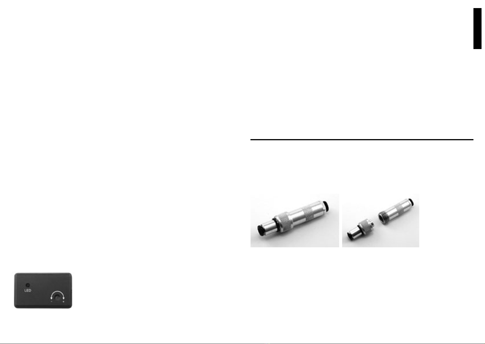
Questo giunto permette di separare e riunire due sezioni di qualsiasi impianto idraulico (carrelli
o freni) senza alcuna perdita di pressione e di olio dal circuito.
All’interno di questo giunto sono presenti due valvole dal funzionamento automatico; mentre viene
svitata la ghiera centrale per separare le due parti del giunto, le valvole si chiudono automaticamente
per evitare la perdita di olio o di pressione.
Al contrario quando le due parti vengono unite e la ghiera centrale viene avvitata, le due valvole
si aprono per permettere nuovamente il passaggio dell’olio.
Questo giunto può essere utilizzato nei modelli che hanno il carrello principale installato nell’ala
o nelle semiali smontabili dalla fusoliera.
In questi casi l’impianto idraulico può essere installato completamente in fusoliera e l’ala o le
semiali possono essere separate facilmente dalla fusoliera con il relativo carrello senza alcuna
perdita di olio dal circuito.
Art. RCA/15676/003
GIUNTO ALA-FUSOLIERA A DOPPIA VALVOLA PER IMPIANTI AD OLIO
(da acquistare separatamente)

ITALIANO
CARRELLO
POSTERIORE
SINISTRO
CHIUSURA
CARRELLO
POSTERIORE
DESTRO
CHIUSURA
CARRELLO
ANTERIORE
CHIUSURA
CARRELLO
POSTERIORE
SINISTRO
APERTURA
CARRELLO
POSTERIORE
DESTRO
APERTURA
CARRELLO
ANTERIORE
APERTURA
BATTERIA
4,8 - 6 Volts
POMPA
COLLEGARE ALLA RICEVENTE CON UNA
PROLUNGA A Y ALLO STESSO CANALE DEL
SERVOCOMANDO DEI CARRELLI
POMPA
RITORNO SERBATOIO OLIO
PESCAGGIO SERBATOIO OLIO
(TUBO INTERNO CON PENDOLINO)
KIT IMPIANTO AD OLIO
PER TERNE DI CARRELLI
Professional Line
AL SERVOCOMANDO
DEI CARRELLI
CONNETTORE A CROCE
CONNETTORE A CROCE
DISTRIBUTORE OLIO
CENTRALINA DI COMANDO
CONNETTORE A T
VALVOLA
UNIDIREZIONALE
POMPA ELETTRICA AD INGRANAGGI
CARRELLO
SINISTRO
CHIUSURA
CARRELLO
DESTRO
CHIUSURA
CARRELLO
SINISTRO
APERTURA
CARRELLO
DESTRO
APERTURA
BATTERIA
4,8 - 6 Volts
POMPA
COLLEGARE ALLA RICEVENTE CON UNA
PROLUNGA A Y ALLO STESSO CANALE DEL
SERVOCOMANDO DEI CARRELLI
POMPA
RITORNO SERBATOIO OLIO
PESCAGGIO SERBATOIO OLIO
(TUBO INTERNO CON PENDOLINO)
KIT IMPIANTO AD OLIO
PER COPPIE DI CARRELLI
Professional Line
AL SERVOCOMANDO
DEI CARRELLI
CONNETTORE A T
CONNETTORE A T
DISTRIBUTORE OLIO
CENTRALINA DI COMANDO
CONNETTORE A T
VALVOLA
UNIDIREZIONALE
POMPA ELETTRICA AD INGRANAGGI

ENGLISH
INSTRUCTIONS - PRECAUTIONS
These landing gears are intended for model aircrafts only
and should be used by expert pilots.
Teen-agers under 12 years are advised against using these
landing gears unless under a grown-up’s guidance.
The ready-to-use undercarriage system contains high-pres-
surized oil or air, so DO NOT take out the piping when the
system is under pressure.
DO NOT touch the landing gears when they are in opera-
tion. DO NOT hold them during operation.
Air pressure in the tanks must not exceed 10 bar.
DO NOT let the landing gears work at low pressure or they
would not move correctly.
In case of leakage or damage of any part of the system, DO
NOT make the landing gears work before having them re-
paired.
Non-observance of these instructions/precautions may by
harmful to persons or cause unproper operation.
Euroretracts thank you for choosing their products and warmly
recommend for a proper use of these landing gears to follow
the instructions included in this handbook.
INSTALLING OIL RETRACTS
Once the retracs are secured to the model, install the following components in the fuselage:
• The oil valve + servo unit, previously connected eachother by a steel rod and link.
• The oil tank, to be secured by rubber rings or nylon clamps to a support previosuly
made in the fuselage, and inserting a foam cushion between the tank and the support to dampen
vibrations.
• The electric gear pump, to x by metal o nylon clamps to a support previously made in
the
fuselage, and putting a foam or rubber cushion between the support and the pump to dampen
vibrations.
• The control unit, wrapped in a foam hose and xed by rubber rings to the support in the
fuselage.
• A cell-pack 4,8-6 V 1800 mAh #RCA/15945/00, just as it is done for the control unit.
• The T and cross ttings can be xed to the model or left movable.
Cut the durit tubing to proper size and assemble it according to the oil retracs diagrams provided
with this instruction sheet, taking care not to reverse the connection to the one-way valve or the
pump/tanktubing, or the circuit would not work properly.
The attachments of the tubing to the device tting are made simply by thoroughly pushing the tube
in the quick link : the pipe is automatically locked in place by the inside spring. To take out the
tube push the outer plastic (or metal) ring against the body of the quick link to relax the spring’s
hold, then pull out the tube.
Take off the oil tank reversal tube from both the T-pick-up and, from the pump’s “IN”-pick-up,
the tube that connects the pump with the tank and the relief pipe. Through this tube ll the tank
with about 100-110 c.c. of special oil for hydraulic systems supplied with the kit: air will escape
from the tank through the tank’s reversal tube. Insert either tubes back to the T and to the pump,
taking care not to reverse them.
Link the pump and the 4,8-6 V cell with the respective intakes on the electronic control unit. With
a Y-shaped extension cable link up the control unit and the servo that will operate the oil distributor
at the receiver channel assigned to the L/G’s pull-in/pull-out control.
Turn on your radio control set and move the L/G control joystick to
start the pump which will take in oil from the tank to ll the tubing
of the system. As soon as the gears’ end travel is reached, and the
pump is under major strain (red LED lights up), the control unit will
cut off the circuit. Although the electronic control unit is factory-set,
its sensitivity can be further adjusted by means of a potentiometer.
The sensitivity is increased by turning the potentiometer clockwise:
the pump will stop under minimum strain. On the contrary, turning
the potentiometer anticlockwise will reduce the circuit’s sensitivity and the pump stops when the
power input is higher.

ENGLISH
This ajustment permits to keep the pump operative and to prevent it from to stopping too early,
before the landing gears are completely closed or completely open.
The standard pull-in/pull-out time is abt. 10-20 seconds. However, to avoid a complete unloading
of the battery, the electronic control unit is set for a more extended pump stopping time, up to 45
seconds.
The L/G can pull-in and out eight to ten times with a 1800 mAh cell-pack. For proper system
working make sure the battery is always full-charged.
To complete the initial lling of the system’s tubing, it is necessary to let the landing gear work
several times either ways, to get full air relief from the pipes and the cylinders. In our system no
relief valve is necessary because air, during the initial pull-in/pull-out cycle, is pushed to the oil
tank and there stored once and for all.
If the oil level in the tank goes too much down ll up to avoid air intake through the relief
tubing.
This oil system requires no maintenance, provided it has been properly installed, and it is free of
leaks. Check the oil level in the tank from time to time. Once the tubing system is completely full,
the oil must ll half the tank. It is advisable, prior to ying always to check the good conditions
of the system, by running a L/G opening/closing cycle.
REAR LEFT
L/G CLOSE
REAR RIGHT
L/G CLOSE
FRONT L/G
CLOSE
REAR LEFT
L/G OPEN
REAR RIGHT
L/G OPEN
FRONT L/G
OPEN
BATTERY
4,8 - 6 Volts
PUMP
TO CONNECT TO THE RECEIVER WITH A Y WIRE
TO THE SAME CHANNEL OF L/G SERVO
PUMP
OIL TANK RETURN
OIL TANK PICK-UP
(INTERNAL PIPE WITH PICK-UP)
OIL SYSTEM KIT
FOR 3-LEG L/G
Professional Line
TO L/G SERVO
CROSS CONNECTOR
CROSS CONNECTOR
AIR SUPPLIER
CONTROLLER
T-CONNECTOR
ONE-WAY VALVE
ELECTRIC GEAR-PUMP
Item RCA/15676/003
TWIN-VALVE WING/FUSELAGE JOINT FOR OIL SYSTEMS
(to purchase separately)
This type of joint permits to assemble and separate two sections of whaterver oil system for breaks
or for landing gears with no leakage or pressure loss.
The joint contains two automatic valves: when the central ring that connects the two sections in
unscrewed as to separate one section from the other, the valves close automatically, so barring the
way to oil or pressure.
When, on the contrary, the two sections are re-connected, and screwed together, the valves will
open again to permit oil or pressure circulation.
This joint can be used on models having the main landing gear xed to the wing or in which the
half-wings can be dismounted from the fuselage.
In these models the whole oil system can be entirely installed into the fuselage, and the wing, or
the half-wings can be easily removed still keeping in place the respective landing gear without
any leakage from the hydraulic system.

FRANCAIS
NOTICES ET PRECAUTIONS
L’utilisation de ces trains d’atterrissage est reservée aux
pilots expérimentés et ils sont à utiliser exclusivement dans
le modélisme aérien.
Nous en déconseillons l’usage aux mineurs de 12 ans à moins
qu’ils ne soient assistés par un adulte.
L’installation prête à l’usage contenant de l’huile ou de l’air
sous haute pression, il ne faut pas détacher les tubes lorsque
l’installation est en pression.
Ne vous approchez pas ni tâchez pas de retenir les jambes des
trains durant leur fonctionnement.
Ne pas charger les reservoirs d’air comprimé à plus de 10
bar.
Eviter de faire fonctionner les trains à basse pression, parce que
dans ce cas la retraction ne se passerait pas correctement.
En cas d’endommagement d’une partie de l’installation ou
en présence de pertes d’air, réparer l’installation avant de
l’utiliser.
La non observance de ces règles pourrait donner lieu à des
dommages aux personnes ou à mauvais fonctionnement des
trains d’atterrissage.
Nous vous remercions pour l’attention dediée à nos produits
et nous vous conseillons de suivre attentivement les instruc-
tions et recommandations de ce manuel pour la bonne utilisa-
tion de nos trains d’atterrissage.
LEFT
L/G CLOSE
RIGHT
L/G CLOSE
LEFT
L/G OPEN
RIGHT
L/G OPEN
BATTERY
4,8 - 6 Volts
PUMP
TO CONNECT TO THE RECEIVER WITH A Y WIRE
TO THE SAME CHANNEL OF L/G SERVO
PUMP
OIL TANK RETURN
OIL TANK PICK-UP
(INTERNAL PIPE WITH PICK-UP)
OIL SYSTEM KIT
FOR 2-LEG L/G
Professional Line
TO L/G SERVO
T-CONNECTOR
T-CONNECTOR
AIR SUPPLIER
CONTROLLER
T-CONNECTOR
ONE-WAY VALVE
ELECTRIC GEAR-PUMP

FRANCAIS
aussitôt que de courant augmente.
Grâce à ce type de réglage on peut ménager le travail de la pompe et éviter que celle-ci ne cesse de
fonctionner avant que la course des trains soit terminée. Les temps standard de rentrée ou de sortie
sont de 10-20 sec. environ. Toutefois le module de commande est aussi bien taré pour déconnecter
la pompe après 45 sec. environ, cela an d’éviter le déchargement complet des piles.
En pack d’accus de 1800 mAh est sufsant pour 8 à 10 rentrées/sorties des trains. Il est très important
que l’accus soit toujours bien chargé, pour éviter le risque de fonctionnnement irrégulier.
Pour compléter le remplissement initial du circuit hydraulique il faut actionner maintes fois les
trains dans les deux sens an de permettre à l’air de s’échapper de la canalisation et des cylindres.
Notre circuit n’a pas besoin de soupape de décharge parce que l’air, pendant les cycles initiaux
de rentrée et sortie, est poussé dans le réservoir d’huile pour y rester sans aucune conséquence
fâcheuse.
Si on s’aperçoit que, dans la phase initiale de remplissage du circuit hydraulique, le niveau de
l’huile dans le réservoir a trop baissé, il faut ajouter de l’huile pour éviter que la tubulure pendulaire
n’aspire de l’air au lieu que de l’huile. S’il à été bien réalisé et s’il n’y a pas de pertes, le système
hydraulique n’a pas besoin d’entretien. Une fois que le circuit à été rempli complètement, il suft
de contrôler que le niveau de l’huile atteigne la moitié du réservoir. Avant de commencer un vol
ne manquez pas d’effectuer un cycle complet rentré/sortie pour vérier le bon fonctionnement de
l’installation.
POSE DES TRAINS D’ATTERRISSAGE A HUILE
Une fois que vous avez placé les trains sur votre modèle montez dans le fuselage les composantes
suivantes:
• le distributeur d’huile et le servo correspondant, les reliant par une barre letée et une
chape
acier.
• le réservoir d’huile, à xer par des bracelets élastiques en caoutchouc ou des colliers nylon
au support préalablement taillé dans le fuselage, et interposant entre le support et le réservoir un
rectangle de mousse pour amortir les vibrations.
• la pompe électrique à engrenages, la xant par des colliers de métal ou nylon au support
préalablement taillé dans le fuselage, interposant un rectangle de mousse entre le support et la
pompe pour amortir les vibrations.
• l’unité électronique de contrôle, enveloppée dans un manchon de mousse, à xer dans le
fuselage par des bracelets élastiques en caoutchouc.
• le pack d’accus de 4,8-6 V 1800 mAh art. RCA/15945/000, comme pour l’unité de
contrôle.
• les raccords en T et en croix peuvent être xés au modèle ou laissés ottants.
Coupez le durit à la juste mesure et assemblez-le comme montré dans les plans ci-inclus concernant
les trains rétractables à huile, à deux ou trois jambes, faisant attention à ne pas relier à l’envers la
soupape unidirectionelle ou les tuyaux de la pompe ou du réservoir car dans ce cas le circuit ne
fonctionnerait pas correctement.
Pour insérer les durits dans les raccords il suft de les presser jusqu’au bout dans les raccords
rapides correspondants: le tuyau sera retenu par le ressort intérieur. Pour le détacher, pressez la
bague métal ou plastique vers le corps du raccord rapide an de desserrer l’étreinte du ressort, et
tirez le tuyau.
Détachez du raccord en T le tuyau de retour réservoir huile et, du raccord “IN” de la pompe, le
tuyau qui la relie à la tubulure pendulaire. A travers de celle-ci introduisez dans le réservoir 100
à 110 c.c. d’huile spéciale pour circuits hydrauliques (fourni avec le kit): l’air contenue dans le
réservoir s’échappera par le tuyau de retour. Insérez les deux tuyaux dans le T et dans la pompe
sans les invertir.
Reliez le connecteur électrique de la pompe et le pack d’accus 4,8-6 V aux connecteurs
correspondants sur le module électronique. Par une rallonge en Y connectez le module de
commande et le servo du distributeur d’huile avec la voie du récepteur assignée à la commande
rentré/sortie des trains.
Mettez votre émetteur et actionnez le stick de commande trains:
la pompe démarre en aspirant de l’huile du réservoir pour faire le
remplissage du circuit hydraulique. Aussitôt que les trains auront
atteint leur n de course, soit en ouvrant qu’en rentrant, le majeur
effort de la pompe (signalé par l’allumage du led rouge) est perçu
par le module de commande qui coupera le circuit. Le module est
déjà calé à l’usine; il est toutefois possible en régler la sensibilité
à l’aide d’un potentiomètre: en tournant le potentiomètre dans le sens des aiguilles d’une montre
on augmente la sensibilité du circuit, la pompe est coupée au moindre effort. En tournant le
potentiomètre en sens contraire on reduit la sensibilité du circuit et la pompe cessera de fonctionner
Ce type d’assemblage permit de détacher our réunir deux sections de n’importe quel circuit
hydraulique (soit freins soit treins d’attérrissage) sans aucune perte de pression ou d’huile.
Deux soupapes à fonctionnement automatique se trouvent à l’intérieur du joint; en dévissant
l’embout centrale pour séparer les deux pièces du joint les deux soupapes se referment
automatiquement pour interdire la sortie de l’huile ou une perte pression.
Par contre elles s’ouvriront à nouveau lorsqu’on réunit les deux pièces et on serre l’embout,
rétablissant ainsi la circulation de l’huile.
Nous conseillons ce type d’assemblage pour les modèles ayant le train principal installé dans
l’aile ou dans les demi-ailes démontables.
Dans ces cas l’installation hydraulique peut être entièrement installée dans le fuselage et l’aile ou
les demi-ailes peuvent être aisément ôtées du fuselage avec leur train sans aucune perte d’huile
du circuit.
Article RCA/15676/003
ASSEMBLAGE A DOUBLE SOUPAPE AILE/FUSELAGE POUR LES
CIRCUITS HYDRAULIQUES (vente individuelle)

FRANCAIS
PACK D’ACCUS
4,8 - 6 Volts
POMPE
BRANCHER AU RECEPTEUR PAR UNE
RALLONGE EN Y ET AU MEME CANAL DE LA
SERVOCOMMANDE TRAIN
POMPE
RETOUR RESERVOIR D’HUILE
PLONGEUR RESERVOIR D’HUILE
(PENDULE RESERVOIR)
BOITE DE DISTRIBUTION
OLEODINAMIQUE POUR
ATTERRISSEUR TRIPLE
Professional Line
VERS LE SERVO DE
TRAINS
DISTRIBUTEUR D’HUILE
COMMANDE ELECTRONIQUE
CONNECTEUR EN T
VALVE A SENS
UNIQUE
POMPE ELECTRIQUE A ENGRENAGES
RENTREE DU
TRAIN D’AILE
GAUCHE
RENTREE DU
TRAIN D’AILE
DROIT
RENTREE DU
TRAIN AVANT
SORTIE DU
TRAIN D’AILE
GAUCHE
SORTIE DU
TRAIN D’AILE
DROIT
SORTIE DU
TRAIN AVANT
CONNECTEUR EN CROIX
CONNECTEUR EN CROIX
PACK D’ACCUS
4,8 - 6 Volts
POMPE
BRANCHER AU RECEPTEUR PAR UNE
RALLONGE EN Y ET AU MEME CANAL DE LA
SERVOCOMMANDE TRAIN
POMPE
RETOUR RESERVOIR D’HUILE
PLONGEUR RESERVOIR D’HUILE
(PENDULE RESERVOIR)
BOITE DE DISTRIBUTION
OLEODINAMIQUE POUR
ATTERRISSEUR DOUBLE
Professional Line
VERS LE SERVO DE
TRAINS
DISTRIBUTEUR D’HUILE
COMMANDE ELECTRONIQUE
CONNECTEUR EN T
VALVE A SENS
UNIQUE
POMPE ELECTRIQUE A ENGRENAGES
RENTREE DU
TRAIN GAUCHE
RENTREE DU
TRAIN DROIT
SORTIE DU
TRAIN GAUCHE
SORTIE DU
TRAIN DROIT
CONNECTEUR EN T
CONNECTEUR EN T

DEUTSCH
ANWEISUNGEN UND
VORSICHTSMASSNAHMEN
Diese Fahrwerke dürfen nur von erfahrenen Modellpiloten
benutzt und ausschließlich in Flugzeugmodellen eingesetzt
werden. Jugendliche unter 12 Jahren sollten nur unter der
Aufsicht von erwachsenen Personen damit umgehen.
Schläuche nicht ahnehmen, solange sich die Fahrwerkanlage
unter Druck bendet, denn diese sind mit Luft oder Öl unter
hohem Druck gefüllt. Bitte halten Sie immer zur Anlage den
nötigen Abstand. Fahrwerkbeine nicht zurückhalten, solang
diese sich in Betrieb benden.
Luftaschen nicht überladen! Maximaler Druck: 10 bar.
Fahrwerke nicht in Betrieb setzen, wenn der Druck allzu
niedrig ist, das könnte der ordungsmässen Funktion schädlich
sein.
Fahrwerke nur dann benutzen, wenn sie sich in einwandfreiem
Zustand benden.
Die Nichtbefolgung dieser Hinweise könnte Personenschäden
oder Systemstörungen verursachen.
Die Fa. Euroretracts bedankt sich für Ihr Interesse, welches
Sie dem Produkt entgegenbringen, und empehlt, die in die-
ser Anleitung enthaltenen Anweisungen zu beachten.
HYDRAULISCHE FAHRWERKE
Nachdem die Fahrwerke auf Ihrem Modell festgeschraubt worden sind, werden die folgenden
Teile in den Rumpf eingebaut:
• mittels einer Gewindestange und eines Gabelkopfes das Ölventil mit dem entsprechenden
Servo verbinden;
• den Ölbehälter, der durch Gummiringe oder Plastikschellen auf dem im Rumpf hergestellten
Untersatz befestigt werden muß. Einen vibrationsdämpfenden Schaumgummischnipsel zwischen
Untersatz und Ölbehälter einsetzen.
• die elektrische Zahnradpumpe, die mittels Metall- oder Plastikschellen auf einem im Rumpf
hersgestellten Untersatz zu befestigen ist. Untersatz und Pumpe durch einen vibrationsdämpfenden
Schaumgummi Schnipsel trennen.
• die in einem Gummischlauch umgewickelte elektronische Steuereinheit, die auf einem
Untersatz in dem Rumpf zu befestigen ist.
• 4,8-6 V 1800 mAh Akku-Packs, Art—Nr. RCA/1945/000, desgleichen für die
Steuereinheit.
• Die T oder die Kreuzverbinder und die Fahrwerkstemporegler kann man entweder an
dem Modell befestigen oder auch locker lassen.
Schläuche auf das richtige Maß schneiden. Nach den in dieser Anleitung für die Ölfahrwerke
vorhandenen Schemen zusammen stecken. Für ordentliche Verbindung des Einwegventils oder
der Schläuche zu der Pumpe sorgen; bei verkehrter Verbindung wird der Kreislauf nicht richtig
funktionieren. Was die Einführung der Schläuche in die verschiedenen Verrohrungen oder
Anschlüße angeht, so braucht man nur den Schlauch völlig in die entsprechende Schnellverbindung
einzustecken: der Schlauch wird durch die innensitzende Feder festgeklemmt. Um ihn zu lösen,
drückt man auf den Metall- oder Plastikring außen gegen den Schnellanschluß: die Feder entspannt
sich und der Schlauch läßt sich leicht herausziehen. Einmal von dem Ölrücklaufschläuchen die T-
Verbindung und dann, von der Pumpe, die Verbindungsschläuche zum Ölbehälter abnehmen. Durch
diese Schläuche 100-110 c.c. Spezialöl für hydraulische Kreisläufe (mitgeliefert im Baukasten) in
den Ölbehälter einfüllen; dadurch wird die im Tank bendliche Luft durch den Ölrücklaufschlauch
aus dem Kreislauf gedrückt.
Die zwei Schläuche in die T-Verbindung und in die Pumpe korrekt zurückstecken.
Den elektrischen Konnektor der Pumpe sowie die 4,8-6 V Akku-Packs mit den entsprechenden
Anschlüßen auf der elektronischen Steuereinheit verbinden; ferner, mittels eines Y-
Verlängerungskabels, die Steuereinheit mit dem Servo, das über dem
für das Ein-Ausfahren der Fahrwerke zuständige Empfängerkanal
das Ölventil kontrolliert. Funkgerät einschalten
und den Bedienungshebel der Fahrwerke betätigen: die Pumpe
beginnt Öl vom Tank anzusaugen, um den Kreislauf zu füllen.
Am Ende der Ein-und Ausziehvorgänge, gerade wenn die
Zahnradpumpe unter höchstem Streß ist, schaltet diese durch ein
von der Steuereinheit ausgehendes Signal (rote Warnleuchte)
automatisch ab. Obwohl die Steuereinheit werkseitig geeicht ist,
kann man mit Hilfe eines Potenziometers ihre Empndlichkeit selber regulieren: um diese zu
erhöhen, dreht man das Potenziometer im Uhrzeiger Sinn ( in diesem Fall schaltet die Pumpe
unter der geringsten Anstrengung ab). Will man, umgekehrt, die Empindlichkeit vermindern, so

DEUTSCH
dreht man das Potenziometer gegen den Uhrzeigersinn: in diesem Fall schaltet die Pumpe erst bei
größerer Stromaufnahme ab.
Durch diese Regulierung wird verhindert, daß die Pumpe zu früh, oder gar nicht, ausgeschaltet
wird, und daß die Fahrwerke nur teilweise geöffnet oder geschlossen bleiben.
Die normalen Auszieh-Einziehzeiten betragen 10 bis 20 Sek. Man kann jedoch die Steuereinheit
so einstellen, daß diese Zeit auf 45 Sek. verlängert wird, um die Gefahr einer komplette Entladung
der Batterie auszuschließen.
Eine 1800 mAh reicht für 8-10 Einzieh-Ausziehvorgänge aus. Es soll, für eine reguläre
Funktionierung des Kreislaufes, lediglich darauf geachtet werden, daß die Akku-Packs stets voll
geladen sind.
Um das Füllen des Kreislaufes anfangs zu vervollständigen, muß die Fahrwerksanlage wiederholt,
sowohl beim Schließen als auch beim Öffnen, betätigt werden, damit die in den Schläuchen und
den Zylindern vorhandene Luft restlos ausweichen kann. Unser System bedarf keines Ablassventils,
da die Luft während dieser ersten Entlüftung in den Öltank geleitet wird und dort bleibt, ohne
jegliche Systemstörung zu verursachen.
Beobachtet man im Öltank während des Anfangsfüllens ein überhöhtes Sinken des Ölstandes so
muß man Öl nachfüllen um zu vermeiden, daß das Tanksrohr Luft statt Öl ansaugt.
Ist sie richtig montiert und undicht, so ist die Fahrwerkanlage wartungsfrei. Man soll sich nur
vergewissern, wenn die hydraulische Anlage gefüllt ist, daß der Ölstand bis zur Hälfte des Behälters
reicht.
Wir empfehlen, stets vor jedem Flug die ordnungsmäße Funktion der Anlage zu überprüfen, indem
Sie einen Ausfahr-Einfahrzyklus durchführen.
HAUPTFAHRWERK
LINKS
EINGEFAHREN
HAUPTFAHRWERK
RECHTS
EINGEFAHREN
BUGFAHRWERK
EINGEFAHREN
HAUPTFAHRWERK
LINKS
AUSGEFAHREN
HAUPTFAHRWERK
RECHTS
AUSGEFAHREN
BUGFAHRWERK
AUSGEFAHREN
ÖLTANK-RÜCKHOLSCHLAUCH
ÖLTANKSPENDELROHR
(PENDELSCHLAUCH)
BAUKASTEN
ÖLDRUCKSYSTEM FÜR
DREIRADFAHRWERKE
Professional Line
ZUM FAHRWERKS-
SERVO
KREUZVERBINDUNG
KREUZVERBINDUNG
ÖLHAHN
STEUERUNGSEINHEIT
T-VERBINDUNG
EINWEGVENTIL
AKKU-PACK
4,8 - 6 Volts
PUMPE
DURCH EIN Y-VERLÄNGERUNGSKABEL AN
DEN EMPFÄNGER UND AN DENSELBEN KANAL
DES FAHRWERKSERVOS ANSCHLIESSEN
PUMPE
ELEKTRISCHE ZAHNRADPUMPE
Best. Nr. RCA/15676/003
DOPPELVENTIL- FLÜGEL/RUMPF-VERBINDUNG FÜR
HYDRAULISCHE ÖLANLAGEN ( Einzelteileverkauf )
Diese Art von Verbindung gestattet, zwei Abschnitte jeglicher hydraulischen Fahrwerk- oder
Bremsanlagen zu trennen oder wieder zu Verbinden, unter Erhaltung des Kreisdruckes und ohne
Ölleck.
Diese Verbindung enthält zwei automatische Ventile, welche sich zur Verhinderung eines Ausießens
der Flüßigkeit oder einer Druckverlust automatisch schliessen, sobald der Mittelring aufgedreht wird,
um die Verbindungsteile zu trennen.
Werden die zwei Teile wieder angeschlossen, und der Ring eingeschraubt, so öffnen sich beide Ventile,
und der Ölkreislauf stellt sich wieder her.
Diese Art von Verbindung eignet sich für Modelugzeuge, in denen das Hauptfahrwerk in der Tragäche
oder in den abnehmbaren Halbügeln sitzt.
In solchen Fällen kann die hydraulische Anlage ganz in dem Rumpf eingebaut werden, und die Tragäche
oder die zwei Halbügel lassen sich samt Fahrwerk leicht und leckfrei von dem Rumpf abnehmen.

DEUTSCH
FAHRWERK
LINKS
EINGEFAHREN
FAHRWERK
RECHTS
EINGEFAHREN
FAHRWERK
LINKS
AUSGEFAHREN
FAHRWERK
RECHTS
AUSGEFAHREN
ÖLTANK-RÜCKHOLSCHLAUCH
ÖLTANKSPENDELROHR
(PENDELSCHLAUCH)
BAUKASTEN
ÖLDRUCKSYSTEM FÜR
ZWEIRADFAHRWERKE
Professional Line
ZUM FAHRWERKS-
SERVO
T-VERBINDUNG
T-VERBINDUNG
ÖLHAHN
STEUERUNGSEINHEIT
T-VERBINDUNG
EINWEGVENTIL
AKKU-PACK
4,8 - 6 Volts
PUMPE
DURCH EIN Y-VERLÄNGERUNGSKABEL AN
DEN EMPFÄNGER UND AN DENSELBEN KANAL
DES FAHRWERKSERVOS ANSCHLIESSEN
PUMPE
ELEKTRISCHE ZAHNRADPUMPE

Euroretracts
Via Enrico Fermi 47
51010 Massa e Cozzile
Pistoia - ITALY
Tel./Fax +39 0572 770899
email: [email protected]
Per aggiornamenti su nuovi prodotti, cataloghi, istruzioni consultate regolar-
mente i nostri siti web: www.euroretracts.it - www.eurokitshop.it
For new product updating, catalogues, instructions please visit our web sites:
www.euroretracts.it - www.eurokitshop.it
Prenez vision des nouveautés, catalogues, notices en consultant notre pages
web: www.euroretracts.it - www.eurokitshop.it
Besuchen Sie uns bitte unter www.euroretracts.it - www.eurokitshop.it, um
Einsicht in unsere neuen Produkte, Kataloge, Informationen zu nehmen.
November 2014 revision
This manual suits for next models
1
Table of contents
Languages: