Deep Sea Electronics Plc DSE8660 MKII User manual

057-259 ISSUE: 1
DEEP SEA ELECTRONICS PLC
DSE8660 MKII Operator Manual
Document Number: 057-259
Author: Fady Atallah

DSE8660 MKII Operator Manual
057-259 ISSUE: 1 Page 2 of 146
Deep Sea Electronics Plc
Highfield House
Hunmanby
North Yorkshire
YO14 0PH
ENGLAND
Sales Tel: +44 (0) 1723 890099
Sales Fax: +44 (0) 1723 893303
E-mail: sales@deepseaplc.com
Website: www.deepseaplc.com
DSE8660 MKII Operator Manual
© Deep Sea Electronics Plc
All rights reserved. No part of this publication may be reproduced in any material form (including
photocopying or storing in any medium by electronic means or other) without the written permission of
the copyright holder except in accordance with the provisions of the Copyright, Designs and Patents
Act 1988.
Applications for the copyright holder’s written permission to reproduce any part of this publication
must be addressed to Deep Sea Electronics Plc at the address above.
The DSE logo and the names DSEGenset
®
, DSEAts
®
and DSEPower
®
are UK registered trademarks
of Deep Sea Electronics PLC.
Any reference to trademarked product names used within this publication is owned by their respective
companies.
Deep Sea Electronics Plc reserves the right to change the contents of this document without prior
notice.
Amendments Since Last Publication
Amd. No.
Comments
1 Initial Release

DSE8660 MKII Operator Manual
Page 3 of 146 057-259 ISSUE: 1
TABLE OF CONTENTS
Section Page
1
INTRODUCTION..................................................................................................7
1.1
CLARIFICATION OF NOTATION........................................................................................ 8
1.2
GLOSSARY OF TERMS..................................................................................................... 8
1.3
BIBLIOGRAPHY............................................................................................................... 10
1.3.1
INSTALLATION INSTRUCTIONS............................................................................... 10
1.3.2
MANUALS.................................................................................................................. 10
1.3.3
TRAINING GUIDES.................................................................................................... 11
1.3.4
THIRD PARTY DOCUMENTS.................................................................................... 11
2
SPECIFICATION................................................................................................12
2.1
OPERATING TEMPERATURE ......................................................................................... 12
2.1.1
SCREEN HEATER OPERATION (WHEN FITTED)..................................................... 12
2.2
REQUIREMENTS FOR UL................................................................................................ 12
2.3
TERMINAL SPECIFICATION............................................................................................ 13
2.4
POWER SUPPLY REQUIREMENTS................................................................................. 13
2.4.1
MODULE SUPPLY INSTRUMENTATION DISPLAY................................................... 13
2.5
VOLTAGE & FREQUENCY SENSING.............................................................................. 14
2.6
CURRENT SENSING........................................................................................................ 14
2.6.1
VA RATING OF THE CTS.......................................................................................... 15
2.6.2
CT POLARITY............................................................................................................ 16
2.6.3
CT PHASING............................................................................................................. 16
2.6.4
CT CLASS.................................................................................................................. 16
2.7
INPUTS............................................................................................................................. 17
2.7.1
DIGITAL INPUTS ....................................................................................................... 17
2.8
OUTPUTS......................................................................................................................... 17
2.8.1
CONFIGURABLE VOLT-FREE RELAY OUTPUTS C & D........................................... 17
2.8.2
CONFIGURABLE DC OUTPUTS E, F, G, H, I & J ...................................................... 17
2.9
COMMUNICATION PORTS .............................................................................................. 18
2.10
COMMUNICATION PORT USAGE................................................................................ 19
2.10.1
USB SLAVE PORT (PC CONFIGURATION) .............................................................. 19
2.10.1.1
USB HOST PORT (USB STORAGE DEVICE CONNECTION)............................. 19
2.10.2
RS232 PORT............................................................................................................. 20
2.10.2.1
RECOMMENDED EXTERNAL MODEMS............................................................ 20
2.10.2.2
RECOMMENDED PC RS232 SERIAL PORT ADD-ONS ..................................... 21
2.10.3
RS485 PORT............................................................................................................. 22
2.10.3.1
CABLE SPECIFICATION..................................................................................... 22
2.10.3.2
RECOMMENDED PC RS485 SERIAL PORT ADD-ONS ..................................... 23
2.10.4
ETHERNET PORT..................................................................................................... 24
2.10.4.1
DIRECT PC CONNECTION................................................................................. 25
2.10.4.2
CONNECTION TO BASIC ETHERNET ............................................................... 26
2.10.4.3
CONNECTION TO COMPANY INFRASTRUCTURE ETHERNET ....................... 27
2.10.4.4
CONNECTION TO THE INTERNET.................................................................... 28
2.10.4.5
FIREWALL CONFIGURATION FOR INTERNET ACCESS .................................. 29
2.10.5
MSC (MULTI-SET COMMUNICATIONS) LINK........................................................... 30
2.10.7
CAN PORT................................................................................................................. 31
2.10.8
DSENET
®
(EXPANSION MODULES)......................................................................... 31
2.11
SOUNDER..................................................................................................................... 32
2.11.1
ADDING AN EXTERNAL SOUNDER.......................................................................... 32
2.12
ACCUMULATED INSTRUMENTATION......................................................................... 32
2.13
DIMENSIONS AND MOUNTING.................................................................................... 33
2.13.1
DIMENSIONS............................................................................................................. 33
2.13.2
PANEL CUTOUT........................................................................................................ 33
2.13.3
WEIGHT..................................................................................................................... 33
2.13.4
FIXING CLIPS............................................................................................................ 34
2.13.5
CABLE TIE FIXING POINTS ...................................................................................... 35
2.13.6
SILICON SEALING GASKET...................................................................................... 35

DSE8660 MKII Operator Manual
057-259 ISSUE: 1 Page 4 of 146
2.14
APPLICABLE STANDARDS......................................................................................... 36
2.14.1
ENCLOSURE CLASSIFICATIONS............................................................................. 38
2.14.1.1
IP CLASSIFICATIONS......................................................................................... 38
2.14.1.2
NEMA CLASSIFICATIONS.................................................................................. 38
3
INSTALLATION.................................................................................................39
3.1
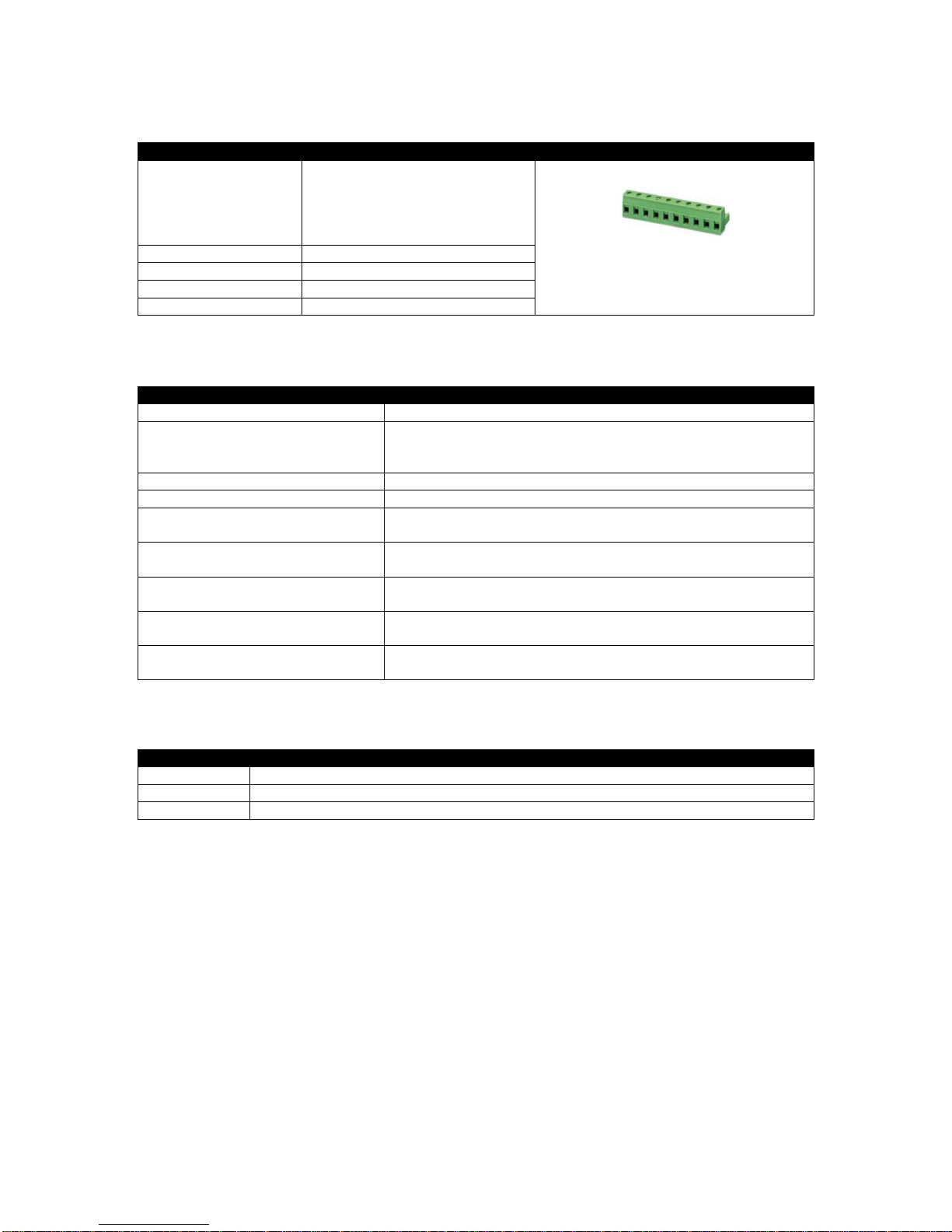
USER CONNECTIONS..................................................................................................... 39
3.2
CONNECTION DESCRIPTIONS....................................................................................... 40
3.2.1
DC SUPPLY & DC OUTPUTS.................................................................................... 40
3.2.2
MSC & DSENET
®
....................................................................................................... 41
3.2.3
OUTPUT C & D & V1 (MAINS) VOLTAGE & FREQUENCY SENSING ....................... 42
3.2.4
V2 (BUS) VOLTAGE & FREQUENCY SENSING........................................................ 42
3.2.5
MAINS CURRENT TRANSFORMERS........................................................................ 43
3.2.6
BUS/LOAD CURRENT TRANSFORMER................................................................... 44
3.2.6.1
ADVANTAGES OF BUS/LOAD CT...................................................................... 44
3.2.7
DIGITAL INPUTS ....................................................................................................... 45
3.2.8
RS485........................................................................................................................ 46
3.2.9
RS232........................................................................................................................ 47
3.2.10
USB SLAVE (PC CONFIGURATION) CONNECTOR.................................................. 48
3.2.11
USB HOST (DATA LOGGING) CONNECTOR............................................................ 48
3.3
TYPICAL WIRING DIAGRAM (3 PHASE, 4 WIRE STAR)................................................. 49
3.4
ALTERNATE TOPOLOGY WIRING DIAGRAMS.............................................................. 50
3.4.1
3 PHASE 3 WIRE DELTA........................................................................................... 50
3.4.2
SINGLE PHASE (L1 & N) 2 WIRE .............................................................................. 51
3.4.3
SINGLE PHASE (L1 & L2) 3 WIRE............................................................................. 52
3.4.4
SINGLE PHASE (L1 & L3) 3 WIRE............................................................................. 52
3.4.5
2 PHASE (L1 & L2) 3 WIRE........................................................................................ 53
3.4.6
2 PHASE (L1 & L3) 3 WIRE........................................................................................ 53
3.4.7
BUS AND LOAD CURRENT TRANSFORMER POSITION ......................................... 54
3.4.7.1
3 PHASE, 4 WIRE WITH A BUS CURRENT TRANSFORMER............................ 54
3.4.7.2
3 PHASE, 4 WIRE WITH A LOAD CURRENT TRANSFORMER.......................... 55
3.5
TYPICAL ARRANGEMENT OF DSENET
®
........................................................................ 56
3.6
TYPICAL ARRANGEMENT OF MSC LINK....................................................................... 57
3.7
TYPICAL SINGLE LINE APPLICATION DRAWINGS....................................................... 58
3.7.1
MULTI GENERATORS FOR PRIME POWER............................................................. 58
3.7.2
MULTI GENERATORS FOR PRIME POWER WITH BUS COUPLERS ...................... 59
3.7.3
MULTI GENERATORS WITH SINGLE SYNCHRONISING TRANSFER SWITCH....... 60
3.7.4
MULTI GENERATORS WITH TWO SYNCHRONISING TRANSFER SWITCHES....... 61
3.7.5
MULTI GENERATORS & SYNCHRONISING TRANSFER SWITCHES ...................... 62
3.7.6
MULTI GENERATORS & TRANSFER SWITCHES WITH BUS COUPLER................. 63
3.7.7
SINGLE GENERATOR EXPORTING (BASE LOADING) POWER.............................. 64
3.7.8
MULTI GENERATORS EXPORTING (BASE LOADING) POWER.............................. 65
3.7.9
EARTH SYSTEMS..................................................................................................... 66
3.7.9.1
NEGATIVE EARTH ............................................................................................. 66
3.7.9.2
POSITIVE EARTH............................................................................................... 66
3.7.9.3
FLOATING EARTH.............................................................................................. 66
4
DESCRIPTION OF CONTROLS........................................................................67
4.1
CONTROL PUSH BUTTONS............................................................................................ 68
4.2
VIEWING THE INSTRUMENT PAGES.............................................................................. 72
4.2.1
STATUS..................................................................................................................... 73
4.2.1.1
ELECTRICAL TRIP ............................................................................................. 73
4.2.2
MAINS........................................................................................................................ 74
4.2.2.2
SYNCHROSCOPE OPERATION......................................................................... 75
4.2.3
BUS ........................................................................................................................... 76
4.2.3.1
COMMISSIONING SCREENS............................................................................. 77
4.2.4
EXPANSION.............................................................................................................. 78
4.2.5
ALARMS.................................................................................................................... 79
4.2.6
EVENT LOG............................................................................................................... 80
4.2.7
SERIAL PORT............................................................................................................ 81
4.2.7.1
RS232 SERIAL PORT......................................................................................... 81

DSE8660 MKII Operator Manual
Page 5 of 146 057-259 ISSUE: 1
4.2.7.2
RS485 SERIAL PORT......................................................................................... 85
4.2.8
ABOUT....................................................................................................................... 86
4.2.8.1
MODULE INFORMATION.................................................................................... 86
4.2.8.2
ETHERNET......................................................................................................... 87
4.2.8.3
DATA LOGGING................................................................................................. 88
4.3
USER CONFIGURABLE INDICATORS............................................................................ 89
5
OPERATION......................................................................................................90
5.1
QUICKSTART GUIDE....................................................................................................... 90
5.1.1
STARTING THE GENERATOR(S).............................................................................. 90
5.1.2
STOPPING THE GENERATOR(S)............................................................................. 91
5.2
STOP/RESET MODE........................................................................................................ 92
5.3
MANUAL MODE............................................................................................................... 93
5.3.1
STARTING SEQUENCE............................................................................................. 93
5.3.2
LOADING GENERATOR BUS.................................................................................... 94
5.3.2.1
BUS MODE......................................................................................................... 94
5.3.2.2
MAINS MODE..................................................................................................... 94
5.3.3
UNLOADING GENERATOR BUS............................................................................... 95
5.3.4
STOPPING SEQUENCE............................................................................................ 95
5.4
TEST MODE..................................................................................................................... 96
5.4.1
STARTING SEQUENCE............................................................................................. 96
5.4.2
LOADING GENERATOR BUS.................................................................................... 97
5.4.2.1
BUS MODE......................................................................................................... 97
5.4.2.2
MAINS MODE..................................................................................................... 97
5.4.3
UNLOADING GENERATOR BUS (FROM CONTINUOUS PARALLEL)....................... 98
5.4.4
UNLOADING GENERATOR BUS (FROM ISLAND MODE) ........................................ 98
5.4.5
STOPPING SEQUENCE............................................................................................ 98
5.5
AUTOMATIC MODE........................................................................................................ 99
5.5.1
WAITING IN AUTO MODE......................................................................................... 99
5.5.2
STARTING SEQUENCE............................................................................................. 99
5.5.3
GENERATOR BUS AVAILABLE............................................................................... 100
5.5.3.1
BUS MODE....................................................................................................... 100
5.5.3.2
MAINS MODE................................................................................................... 100
5.5.4
UNLOADING GENERATOR BUS............................................................................. 101
5.5.5
STOPPING SEQUENCE.......................................................................................... 101
5.6
MULTIPLE MAINS OPERATION .................................................................................... 102
5.6.1
8660 PRIORITY ....................................................................................................... 102
5.6.2
DSE8660 MKII LOAD CT.......................................................................................... 103
5.7
SCHEDULER.................................................................................................................. 104
5.7.1
STOP/RESET MODE............................................................................................... 104
5.7.2
MANUAL MODE....................................................................................................... 104
5.7.3
TEST MODE............................................................................................................ 105
5.7.4
AUTO MODE............................................................................................................ 105
5.8
MSC COMPATIBILITY MODE ........................................................................................ 106
5.9
SMS CONTROL.............................................................................................................. 107
5.10
DEAD BUS SYNCHRONISING (AUTO MODE)........................................................... 108
5.10.1
BENEFIT OF SYSTEM............................................................................................. 108
5.10.2
HARDWARE REQUIREMENTS ............................................................................... 108
5.10.3
OPERATION............................................................................................................ 109
6
PROTECTIONS................................................................................................110
6.1
ALARMS......................................................................................................................... 110
6.2
INDICATIONS................................................................................................................. 111
6.3
WARNING ALARMS....................................................................................................... 112
6.4
ELECTRICAL TRIP ALARMS......................................................................................... 116
6.5
MAINS DECOUPLING ALARMS .................................................................................... 120
7
FRONT PANEL CONFIGURATION.................................................................121
7.1
MAIN CONFIGURATION EDTIOR.................................................................................. 122
7.1.1
ACESSING THE MAIN CONFIGURATION EDTIOR................................................. 122
7.1.2
ENTERING PIN........................................................................................................ 122

DSE8660 MKII Operator Manual
057-259 ISSUE: 1 Page 6 of 146
7.1.3
EDITING A PARAMETER......................................................................................... 123
7.1.4
EXITING THE MAIN CONFIGURATION EDITOR..................................................... 123
7.1.5
ADJUSTABLE PARAMETERS................................................................................. 124
7.2
‘RUNNING’ CONFIGURATION EDITOR......................................................................... 125
7.2.1
ACCESSING THE ‘RUNNING’ CONFIGURATION EDITOR..................................... 125
7.2.2
ENTERING PIN........................................................................................................ 125
7.2.3
EDITING A PARAMETER......................................................................................... 125
7.2.4
EXITING THE ‘RUNNING’ CONFIGURATION EDITOR............................................ 126
7.2.5
RUNNING EDITOR PARAMETERS ......................................................................... 126
8
COMMISSIONING............................................................................................127
8.1
BASIC CHECKS............................................................................................................. 127
8.2
DSE 4 STEPS TO SUCCESSFUL SYNCHRONISING..................................................... 128
8.2.1
CONTROL................................................................................................................ 129
8.2.1.1
DETERMINING CONNECTIONS AND SETTINGS FOR GOVERNORS............ 129
8.2.1.2
DETERMINING CONNECTIONS AND SETTINGS FOR AVRS ......................... 131
8.2.2
METERING.............................................................................................................. 133
8.2.2.1
CTS ON THE RIGHT PHASE............................................................................ 133
8.2.2.2
CTS IN THE RIGHT DIRECTION....................................................................... 133
8.2.3
COMMUNICATIONS................................................................................................ 134
8.2.4
SYNC CHECKS ....................................................................................................... 135
8.2.4.1
INCORRECTLY WIRED BREAKER................................................................... 136
8.2.4.2
CORRECTLY WIRED BREAKER...................................................................... 137
9
FAULT FINDING..............................................................................................138
9.1
STARTING...................................................................................................................... 138
9.2
INSTRUMENTS .............................................................................................................. 139
9.3
LOADING ....................................................................................................................... 139
9.4
COMMUNICATIONS....................................................................................................... 140
9.5
MISCELLANEOUS ......................................................................................................... 141
10
MAINTENANCE, SPARES, REPAIR AND SERVICING ..............................142
10.1
PURCHASING ADDITIONAL CONNECTOR PLUGS FROM DSE............................... 142
10.1.1
PACK OF PLUGS..................................................................................................... 142
10.1.2
INDIVIDUAL PLUGS................................................................................................ 142
10.2
PURCHASING ADDITIONAL FIXING CLIPS FROM DSE ........................................... 142
10.3
PURCHASING ADDITIONAL SEALING GASKET FROM DSE................................... 143
10.4
DSENET
®
EXPANSION MODULES............................................................................. 143
11
WARRANTY .................................................................................................144
12
DISPOSAL....................................................................................................144
12.1
WEEE (WASTE ELECTRICAL AND ELECTRONIC EQUIPMENT) ............................. 144

Introduction
Page 7 of 146 057-259 ISSUE: 1
1 INTRODUCTION
This document details the installation and operation requirements of the DSE8660 MKII module and is
part of the DSEGenset® range of products.
The manual forms part of the product and should be kept for the entire life of the product. If the
product is passed or supplied to another party, ensure that this document is passed to them for
reference purposes.
This is not a controlled document. DSE do not automatically inform on updates. Any future updates of
this document are included on the DSE website at www.deepseaplc.com
The DSE86xx MKII series is designed to provide differing levels of functionality across a common
platform. This allows the generator OEM greater flexibility in the choice of controller to use for a
specific application.
The DSE8660 MKII module is designed to provide differing levels of functionality across a common
platform. This allows the generator OEM greater flexibility in the choice of controller to use for a
specific application.
Synchronsing and Load Sharing features are included within the controller, along with the necessary
protections for such a system.
The user also has the facility to view the system operating parameters via the text LCD display.
The DSE8660 MKII module has been designed to monitor the mains (utility) supply and automatically
start/stop one or more generator sets equipped with DSE8610 MKII controllers depending upon the
status of the mains (utility) supply.
The powerful ARM microprocessor contained within the module allows for incorporation of a range of
complex features:
Text based LCD display
True RMS Voltage
Current and Power monitoring
USB, RS232, RS485 and Ethernet Communications
Fully configurable inputs for use as alarms or a range of different functions.
Synchronising and load sharing with load demand start/stop
Integral PLC to help provide customisation where required
Data Logging
R.O.C.O.F. and vector shift protection for detection of mains failure when in parallel with the mains.
The DSE Configuration Suite PC Software allows alteration of selected operational sequences,
timers, alarms and operational sequences. Additionally, the module’s integral front panel configuration
editor allows adjustment of this information.
Access to critical operational sequences and timers for use by qualified engineers, can be protected
by a security code. Module access can also be protected by PIN code. Selected parameters can be
changed from the module’s front panel.
The module is housed in a robust plastic case suitable for panel mounting. Connections to the module
are via locking plug and sockets.

Introduction
057-259 ISSUE: 1 Page 8 of 146
1.1 CLARIFICATION OF NOTATION
Clarification of notation used within this publication.
NOTE:
Highlights an essential element of a procedure to ensure correctness.
CAUTION!
Indicates a procedure or practice, which, if not strictly observed, could
result in damage or destruction of equipment.
WARNING!
Indicates a procedure or practice, which could result in injury to personnel
or loss of life if not followed correctly.
1.2 GLOSSARY OF TERMS
Term
Description
DSE8000 MKII,
DSE8xxx MKII All modules in the DSE8xxx MKII range.
DSE8600 MKII,
DSE86xx MKII All modules in the DSE86xx MKII range.
DSE8660 MKII DSE8660 MKII module/controller
DSE8x10 DSE8610, DSE8610 MKII, DSE8710 and DSE8810 module/controller
DSE8x60 DSE8660, DSE8660 MKII, DSE8760 and DSE8860 module/controller
DSE8x80 DSE8680 module/controller
CAN Controller Area Network
Vehicle standard to allow digital devices to communicate to one another.
CDMA Code Division Multiple Access.
Cell phone access used in small number of areas including parts of the USA and
Australia.
CT Current Transformer
An electrical device that takes a large AC current and scales it down by a fixed
ratio to a smaller current.
BMS Building Management System
A digital/computer based control system for a building’s infrastructure.
GSM Global System for Mobile communications. Cell phone technology used in most of
the World.
HMI Human Machine Interface
A device that provides a control and visualisation interface between a human and a
process or machine.
IDMT Inverse Definite Minimum Time
IEEE Institute of Electrical and Electronics Engineers
LED Light Emitting Diode
MSC Multi-Set Communication
PLC Programmable Logic Controller
A programmable digital device used to create logic for a specific purpose.
R.O.C.O.F. Rate Of Change Of Frequency
SCADA Supervisory Control And Data Acquisition
A system that operates with coded signals over communication channels to
provide control and monitoring of remote equipment
SCR Selective Catalytic Reduction
A process that uses DEF with the aid of a catalyst to convert nitric oxide and
nitrogen dioxide into nitrogen and water to reduce engine exhaust emission.
Continued over page…

Introduction
Page 9 of 146 057-259 ISSUE: 1
Term
Description
SIM Subscriber Identity Module.
The small card supplied by the GSM/CDMA provider that is inserted into the cell
phone, GSM modem or DSEGateway device to give GSM/GPRS connection.
SMS Short Message Service
The text messaging service of mobile/cell phones.
SPN Suspect Parameter Number
A part of DTC that indicates what the failure is, e.g. oil pressure, coolant
temperature, turbo pressure etc.

Introduction
057-259 ISSUE: 1 Page 10 of 146
1.3 BIBLIOGRAPHY
This document refers to, and is referred by the following DSE publications which are obtained from
the DSE website: www.deepseaplc.com or by contacting DSE technical support:
support@deepseaplc.com.
1.3.1 INSTALLATION INSTRUCTIONS
Installation instructions are supplied with the product in the box and are intended as a ‘quick start’
guide only.
DSE
Part
Description
053-032 DSE2548 LED Expansion Annunciator Installation Instructions
053-033 DSE2130 Input Expansion Installation Instructions
053-034 DSE2157 Output Expansion Installation Instructions
053-125 DSE2131 Ratio-metric Input Expansion Installation Instructions
053-126 DSE2133 RTD/Thermocouple Input Expansion Installation Instructions
053-134 DSE2152 Ratio-metric Output Expansion Installation Instructions
053-184 DSE8660 MKII Installation Instructions
1.3.2 MANUALS
Product manuals are obtained from the DSE website: www.deepseaplc.com or by contacting DSE
technical support: support@deepseaplc.com.
D
SE
Part
Description
N/A DSEGencomm (MODBUS protocol for DSE controllers)
057-045 Guide to Synchronising and Load Sharing Part 1
(Usage of DSE Load Share Controllers in synchronisation / load sharing systems.)
057-046 Guide to Synchronising and Load Sharing Part 2 (Governor & AVR Interfacing)
057-047 Load Share System Design and Commissioning Guide
057-082 DSE2130 Input Expansion Operator Manual
057-083 DSE2157 Output Expansion Operator Manual
057-084 DSE2548 Annunciator Expansion Operator Manual
057-139 DSE2131 Ratio-metric Input Expansion Manual
057-140 DSE2133 RTD/Thermocouple Expansion Manual
057-141 DSE2152 Ratio-metric Output Expansion Manual
057-151 DSE Configuration Suite PC Software Installation & Operation Manual
057-175 PLC Programming Guide For DSE Controllers
057-220 Options for Communications with DSE Controllers
057-257 DSE8660 MKII Configuration Suite PC Software Manual

Introduction
Page 11 of 146 057-259 ISSUE: 1
1.3.3 TRAINING GUIDES
Training guides are provided as ‘hand-out’ sheets on specific subjects during training sessions and
contain specific information regarding to that subject.
D
SE
Part
Description
056-001 Four Steps To Synchronising
056-005 Using CTs With DSE Products
056-006 Introduction to Comms
056-010 Over Current Protection
056-011 MSC Link
056-013 Load Demand Scheme
056-021 Mains Decoupling
056-022 Breaker Control
056-024 GSM Modem
056-026 kW, kvar, kVA and pf.
056-030 Module PIN Codes
056-032 xx60 with no bus breaker
056-033 Synchronising Requirements
056-036 Expansion Modules
056-042 Bus mode or Mains mode
056-043 Sync Process
056-047 Out of Sync and Failed To Close
056-051 Sending DSEGencom Control Keys
056-053 Recommended Modems
056-069 Firmware Update
056-072 Dead Bus Synchronising
056-075 Adding Language Files
056-076 Reading DSEGencom Alarms
056-079 Reading DSEGencom Status
056-080 MODBUS
056-081 Screen Heaters
056-082 Override Gencomm PLC Example
056-083 Synchronising & Loadsharing
056-086 G59
1.3.4 THIRD PARTY DOCUMENTS
The following third party documents are also referred to:
Reference
Description
ISBN 1-55937-879-4 IEEE Std C37.2-1996 IEEE Standard Electrical Power System Device
Function Numbers and Contact Designations. Institute of Electrical and
Electronics Engineers Inc
ISBN 0-7506-1147-2 Diesel generator handbook. L.L.J. Mahon
ISBN 0-9625949-3-8 On-Site Power Generation. EGSA Education Committee.

Specification
057-259 ISSUE: 1 Page 12 of 146
2 SPECIFICATION
2.1 OPERATING TEMPERATURE
Module
Specification
DSE86xx MKII -30 ºC +70 ºC (-22 ºF +158 ºF )
Display Heater Variants -40 ºC +70 ºC (-40 ºF +158 ºF )
2.1.1 SCREEN HEATER OPERATION (WHEN FITTED)
Screen Heater Function
Specification
Turn On When Temperature Falls Below -10 ºC (+14 ºF)
Turn Off When Temperature Rises Above -5 ºC (+23 ºF)
2.2 REQUIREMENTS FOR UL
Description
Specification
Screw Terminal
Tightening Torque 4.5 lb-in (0.5 Nm)
Conductors
Terminals suitable for connection of conductor size 12 AWG to 26 AWG
(0.5 mm² to 2.0 mm²).
Conductor protection must be provided in accordance with NFPA 70,
Article 240
Low voltage circuits (35 V or less) must be supplied from the engine
starting battery or an isolated secondary circuit.
The communication, sensor, and/or battery derived circuit conductors
shall be separated and secured to maintain at least ¼” (6 mm) separation
from the generator and mains connected circuit conductors unless all
conductors are rated 600 V or greater.
Current Inputs Must be connected through UL Listed or Recognized isolating current
transformers with the secondary rating of 5 A max.
Communication Circuits Must be connected to communication circuits of UL Listed equipment
Output Pilot Duty 0.5 A
Mounting
Suitable for use in type 1 Enclosure Type rating with surrounding air
temperature -22 ºF to +158 ºF (-30 ºC to +70 ºC)
Suitable for pollution degree 3 environments when voltage sensing inputs
do not exceed 300 V. When used to monitor voltages over
300 V device to be installed in an unventilated or filtered ventilation
enclosure to maintain a pollution degree 2 environment.
Operating Temperature -22 ºF to +158 ºF (-30 ºC to +70 ºC)
Storage Temperature -40 ºF to +176 ºF (-40 ºC to +80 ºC)

Specification
Page 13 of 146 057-259 ISSUE: 1
2.3 TERMINAL SPECIFICATION
Description
Specification
Connection Type
Two part connector.
Male part fitted to module
Female part supplied in module
packing case - Screw terminal,
rising clamp, no internal spring.
Example showing cable entry and screw
terminals of a 10 way connector
Minimum Cable Size 0.5 mm² (AWG 24)
Maximum Cable Size 2.5 mm² (AWG 12)
Tightening Torque 0.5 Nm (4.5 lb-in)
Wire Strip Length 7 mm (9/32”)
2.4 POWER SUPPLY REQUIREMENTS
Description
Specification
Minimum Supply Voltage 5 V continuous
Cranking Dropouts
Able to survive 0 V for 100 ms providing the supply was at least
was greater than 5 V for 2 seconds before the dropout and
recovers to 5 V afterwards.
Maximum Supply Voltage 35 V continuous (60 V protection)
Reverse Polarity Protection -35 V continuous
Maximum Operating Current 530 mA at 12 V
280 mA at 24 V
Maximum Standby Current 320 mA at 12 V
120 mA at 24 V
Maximum Current When In Sleep
Mode 140 mA at 12 V
75 mA at 24 V
Typical Power
(Controller On, Heater Off) 3.8 W to 4.1 W
Typical Power
(Controller On, Heater On) 6.8 W to 7.1 W
2.4.1 MODULE SUPPLY INSTRUMENTATION DISPLAY
Description
Specification
Range 0 V to 70 V DC (Maximum continuous operating voltage of 35 V DC)
Resolution 0.1 V
Accuracy 1 % full scale (±0.35 V)

Specification
057-259 ISSUE: 1 Page 14 of 146
2.5 VOLTAGE & FREQUENCY SENSING
Description
Specification
Measurement Type True RMS conversion
Sample Rate 40 kHz
Harmonics Up to 21
st
or better
Input Impedance 300 kΩphase to neutral
Phase To Neutral 15 V (minimum required for sensing frequency) to 415 V AC
(absolute maximum)
Suitable for 345 V AC nominal
(±20 % for under/overvoltage detection)
Phase To Phase
25 V (minimum required for sensing frequency) to 720 V AC
(absolute maximum)
Suitable for 600 V AC nominal
(±20 % for under/overvoltage detection)
Common Mode Offset From Earth 100 V AC (max)
Resolution 1 V AC phase to neutral
2 V AC phase to phase
Accuracy ±1 % of full scale phase to neutral
±2 % of full scale phase to phase
Minimum Frequency 3.5 Hz
Maximum Frequency 75.0 Hz
Frequency Resolution 0.1 Hz
Frequency Accuracy ±0.05 Hz
2.6 CURRENT SENSING
Description
Specification
Measurement Type True RMS conversion
Sample Rate 40 kHz
Harmonics Up to 21
st
or better
Nominal CT Secondary Rating 1 A and 5 A
Maximum Continuous Current 5 A
Overload Measurement 15 A
Absolute Maximum Overload 50 A for 0.2 second
30 A for 5 second
Burden 0.5 VA (0.02 Ωcurrent shunts)
Common Mode Offset 70 V peak plant ground to CT common terminal under fault
condition
Resolution 25 mA
Accuracy ±1 % of Nominal (excluding CT error)

Specification
Page 15 of 146 057-259 ISSUE: 1
2.6.1 VA RATING OF THE CTS
NOTE: Details for 4 mm² cables are shown for reference only. The connectors on the DSE
modules are only suitable for cables up to 2.5 mm².
The VA burden of the module on the CTs is 0.5 VA. However depending upon the type and length of
cabling between the CTs and the module, CTs with a greater VA rating than the module are required.
The distance between the CTs and the
measuring module should be
estimated and cross-referenced
against the chart opposite to find the
VA burden of the cable itself.
If the CTs are fitted within the
alternator top box, the star point
(common) of the CTs should be
connected to system ground (earth) as
close as possible to the CTs. This
minimises the length of cable used to
connect the CTs to the DSE module.
Example:
If 1.5 mm² cable is used and the
distance from the CT to the measuring
module is 20 m, then the burden of the
cable alone is approximately 15 VA.
As the burden of the DSE controller is
.5 VA, then a CT with a rating of at
least 15 VA + 0.5 VA = 15.5 VA must
be used. 0.5 VA, then a CT with a rating of at least 15 VA + 0.5 VA = 15.5 VA must be used. If 2.5
mm² cables are used over the same distance of 20 m, then the burden of the cable on the CT is
approximately 7 VA. CT’s required in this instance is at least 7.5 VA (7 + 0.5).

Specification
057-259 ISSUE: 1 Page 16 of 146
2.6.2 CT POLARITY
NOTE: Take care to ensure correct polarity of the CT primary as shown above. If in doubt,
check with the CT supplier.
Take care to ensure the correct polarity of the CTs. Incorrect CT orientation leads to negative kW
readings when the set is supplying power. Take note that paper stick-on labels on CTs that show the
orientation are often incorrectly placed on the CT. It is more reliable to use the labelling in the case
moulding as an indicator to orientation (if available).
To test orientation, run the generator in island mode (not in parallel with any other supply) and load
the generator to around 10 % of the set rating. Ensure the DSE module shows positive kW for all
three individual phase readings.
To Generator
To Load
Polarity of CT Primary
2.6.3 CT PHASING
Take particular care that the CTs are connected to the correct phases. For instance, ensure that the
CT on phase 1 is connected to the terminal on the DSE module intended for connection to the CT for
phase 1.
Additionally ensure that the voltage sensing for phase 1 is actually connected to generator phase 1.
Incorrect connection of the phases as described above results in incorrect power factor (pf)
measurements, which in turn results in incorrect kW measurements.
One way to check for this is to make use of a single-phase load. Place the load on each phase in turn,
run the generator and ensure the kW value appears in the correct phase. For instance if the load is
connected to phase 3, ensure the kW figure appears in phase 3 display and not in the display for
phase 1 or 2.
2.6.4 CT CLASS
Ensure the correct CT type is chosen. For instance if the DSE module is providing over current
protection, ensure the CT is capable of measuring the overload level required to protect against, and
at the accuracy level required.
For instance, this may mean fitting a protection class CT (P15 type) to maintain high accuracy while
the CT is measuring overload currents.
Conversely, if the DSE module is using the CT for instrumentation only (current protection is disabled
or not fitted to the controller), then measurement class CTs can be used. Again, bear in mind the
accuracy required. The DSE module is accurate to better than 1% of the full-scale current reading. To
maintain this accuracy, fit a Class 0.5 or Class 1 CT.
Check with the CT manufacturer for further advice on selecting CTs.
Labelled as
p1,
k
or K Labelled as
p2,
l
or L

Specification
Page 17 of 146 057-259 ISSUE: 1
2.7 INPUTS
2.7.1 DIGITAL INPUTS
Description
Specification
Number 12 configurable digital inputs
(16 when Analogue Inputs are configured as digital inputs)
Arrangement Contact between terminal and ground
Low Level Threshold 2.1 V minimum
High Level Threshold 6.6 V maximum
Maximum Input Voltage +50 V DC with respect to plant supply negative
Minimum Input Voltage -24 V DC with respect to plant supply negative
Contact Wetting Current 7 mA typical
Open Circuit Voltage 12 V typical
2.8 OUTPUTS
2.8.1 CONFIGURABLE VOLT-FREE RELAY OUTPUTS C & D
Description
Specification
Type Normally used for load switching control
Fully configurable volt-free relays.
Output C normally closed and Output D normal open.
Rating 8 A resistive at 250 V AC
2.8.2 CONFIGURABLE DC OUTPUTS E, F, G, H, I & J
Description
Specification
Type Fully configurable, supplied from DC supply terminal 2.
Rating 2 A resistive at module supply.

Specification
057-259 ISSUE: 1 Page 18 of 146
2.9 COMMUNICATION PORTS
NOTE: All communication ports can be used at the same time.
Description
Specification
USB Slave Port Type B USB 2.0
For connection to PC running DSE Configuration Suite
Max distance 6 m (20 feet)
USB Host Port Type A USB 2.0
Capability to add a maximum of 16 GB USB storage device for data
recording only
RS232 Serial Port
Non – isolated
Max Baud rate 115 k baud subject to configuration
TX, RX, RTS, CTS, DSR, DTR, DCD
Male 9 way D type connector
Max distance 15 m (50 feet)
2 x RS485 Serial Ports
Isolated
Data connection 2 wire + common
Half Duplex
Data direction control for Transmit (by s/w protocol)
Max Baud Rate 115 k baud subject to configuration
External termination required (120 Ω)
Max common mode offset 70 V (on board protection transorb)
Max distance 1.2 km (¾ mile)
Ethernet Auto detecting 10/100 Mbit Ethernet port.
MSC (Multi Set
Communication) and
CAN Port
NOTE: For additional length, the DSE124 CAN & MSC Extender
is available. For more information, refer to DSE Publication: 057-116
DSE124 Operator Manual
Standard implementation of ‘Slow mode’, up to 250K bits/s
Data connection 2 wire + common
Isolated
External termination required (120 Ω)
Max common mode offset 70 V (on board protection transorb)
Max distance 250 M using Belden 9841 Cable or equivalent
DSENet
®
(Expansion Comms) Port
Non-isolated
Data connection 2 wire + common
Half Duplex
Data direction control for Transmit (by s/w protocol)
Baud Rate of 115 k baud
Internal termination fitted (120 Ω)
Max common mode offset ±5 V
Max distance 1.2 km (¾ mile)

Specification
Page 19 of 146 057-259 ISSUE: 1
2.10 COMMUNICATION PORT USAGE
2.10.1 USB SLAVE PORT (PC CONFIGURATION)
NOTE: DSE stock 2 m (6.5 feet) USB type A to type B cable, DSE Part Number: 016-125.
Alternatively they are purchased from any PC or IT store.
NOTE: The DC supply must be connected to the module for configuration by PC.
NOTE: For further details of module configuration, refer to DSE Publication: 057-257
DSE8660 MKII Configuration Suite PC Software Manual.
The USB port is provided to give a simple means of connection between a PC and the controller.
Using the DSE Configuration Suite Software, the operator is then able to control the module, starting
or stopping the engine, selecting operating modes, etc.
Additionally, the various operating parameters (such as coolant temperature, oil pressure, etc.) of the
engine are available to be viewed or changed.
To connect a module to a PC by USB, the following items are required:
DSE86xx MKII Controller
DSE Configuration Suite PC Software
(Supplied on configuration suite software CD or available from
www.deepseaplc.com).
2.10.1.1 USB HOST PORT (USB STORAGE DEVICE CONNECTION)
USB Type A connection for an of external USB storage device of maximum 16 GB for instrumentation
data logging.

Specification
057-259 ISSUE: 1 Page 20 of 146
2.10.2 RS232 PORT
NOTE: For direct connection an RS232 null modem (crossover) cable is required. This is
rated to a maximum cable length of 15 m.
NOTE: For a single module to PC connection and distances up to 6 m (20 feet) the USB
connection method is more suitable and provides for a lower cost alternative to RS485 (which
is more suited to longer distance connections).
The RS232 port on the controller supports the MODBUS RTU protocol and is for connection to a
single MODBUS master device only.
The MODBUS register table for the controller is available upon request from the DSE Technical
Support Department.
RS232 is for short distance communication (max 15m) and is typically used to connect the controller
to a telephone or GSM modem for more remote communications.
The various operating parameters (such as coolant temperature, oil pressure, etc.) of the remote
engine are viewed or changed.
Many PCs are not fitted with an internal RS232 serial port. DSE DOES NOT recommend the use of
USB to RS232 convertors but can recommend PC add-ons to provide the computer with an RS232
port.
2.10.2.1 RECOMMENDED EXTERNAL MODEMS
NOTE: For GSM modems a SIM card is required, supplied by the GSM network provider:
For SMS only, a ‘normal’ voice SIM card is required. This enables the controller to send SMS
messages to designated mobile phones upon status and alarm conditions.
For a data connection to a PC running DSE Configuration Suite Software, a ‘special’ CSD
(Circuit Switched Data) SIM card is required that enables the modem to answer an incoming
data call. Many ‘pay as you go’ services do not provide a CSD (Circuit Switched Data) SIM
card.
Multitech Global Modem – MultiModem ZBA (PSTN)
Sierra Fastrak Xtend GSM modem kit (PSU, Antenna and modem)*
Table of contents
Other Deep Sea Electronics Plc Control Unit manuals

Deep Sea Electronics Plc
Deep Sea Electronics Plc DSE5320 User manual

Deep Sea Electronics Plc
Deep Sea Electronics Plc DSE5110 User manual

Deep Sea Electronics Plc
Deep Sea Electronics Plc DSE5520 User manual

Deep Sea Electronics Plc
Deep Sea Electronics Plc DSE7450 User manual

Deep Sea Electronics Plc
Deep Sea Electronics Plc DSE6120 MKII User manual

Deep Sea Electronics Plc
Deep Sea Electronics Plc DSE5310 User manual