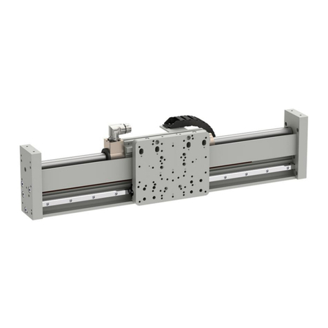
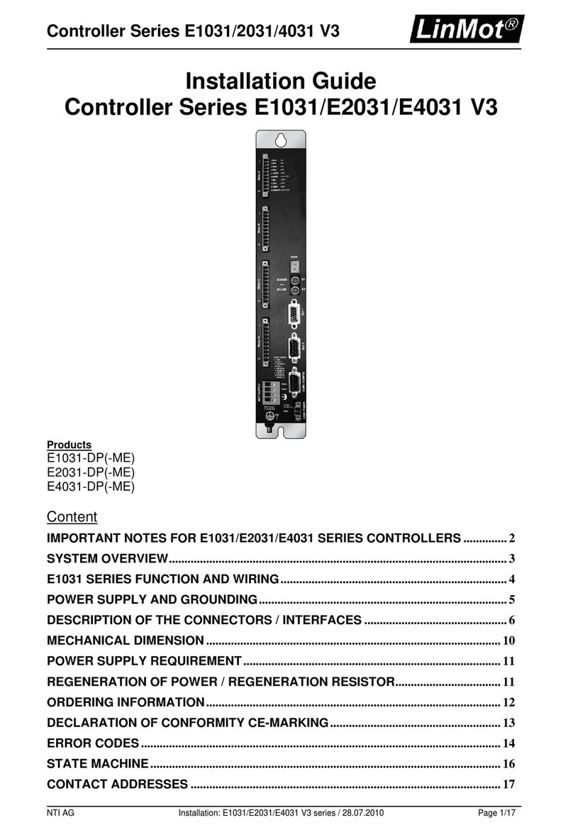
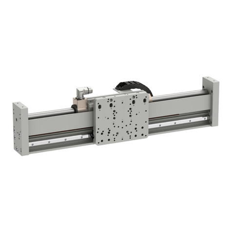
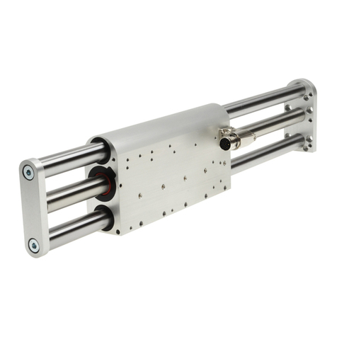
LinMot E1100 Series User manual

Motion Control SW
Documentation of the Motion Control SW
-E1100 / B1100 Drive Series
Motion Control SW
User Manual

L
i
n
M
o
t
Motion Control SW
© 2013 NTI AG
This work is protected by copyright.
Under the copyright laws, this publication may not be reproduced or transmitted in any form, electronic or mechanical, including
photocopying,
recording, microfilm, storing in an information retrieval system, not even for didactical use, or translating, in whole or in
part, without the prior written consent of NTI AG.
LinMot® is a registered trademark of NTI AG.
Note
The information in this documentation reflects the stage of development at the time of press and is therefore without obligation.
NTI AG. reserves itself the right to make changes at any time and without notice to reflect further technical advance or product
improvement.
Document Version 3.17b / Whp, December 2013
age 2/91 User Manual Motion Control SW / 06/12/2013 NTI AG / LinMot

Motion Control SW
L
i
n
M
o
t
TABLE OF CONTENT
SYSTEM OVERVIEW ............................................................................................................ 9
1.1 REFERENCES ......................................................................................................................... 9
1.2 DEFINITIONS, ITEMS, SHORTCUTS ............................................................................................. 9
1.3 DATA TYPES ......................................................................................................................... 9
2 MOTION CONTROL INTERFACES ............................................................................... 10
3 STATE MACHINE .............................................................................................................. 11
3.1 STATE 0: NOT READY TO SWITCH ON .................................................................................. 13
3.2 STATE 1: SWITCH ON DISABLED ........................................................................................... 13
3.3 STATE 2: READY TO SWITCH ON .......................................................................................... 13
3.4 STATE 3: SETUP ERROR STATE ............................................................................................. 13
3.5 STATE 4: ERROR STATE ....................................................................................................... 13
3. STATE 5: HW TEST ............................................................................................................ 13
3.7 STATE : READY TO OPERATE .............................................................................................. 13
3.8 STATE 8: OPERATION ENABLED ............................................................................................. 14
3.9 STATE 9: HOMING ............................................................................................................... 14
3.10 STATE 10: CLEARANCE CHECK ........................................................................................... 14
3.11 STATE 11: GOING TO INITIAL POSITION .............................................................................. 14
3.12 STATE 12: ABORTING ........................................................................................................ 14
3.13 STATE 13: FREEZING ......................................................................................................... 15
3.14 STATE 14: ERROR BEHAVIOUR QUICK STOP ......................................................................... 15
3.15 STATE 15: GOING TO POSITION .......................................................................................... 15
3.1 STATE 1 : JOGGING + ....................................................................................................... 15
3.17 STATE 17: JOGGING - ........................................................................................................ 15
3.18 STATE 18: LINEARIZING ..................................................................................................... 15
3.19 STATE 19: PHASE SEARCHING ............................................................................................. 15
3.20 STATE 20: SPECIAL MODE ................................................................................................. 15
3.21 BUILDING THE CONTROL WORD .......................................................................................... 15
3.22 CONTROL WORD ............................................................................................................... 1
3.23 STATUS WORD .................................................................................................................. 17
3.24 WARN WORD ................................................................................................................... 18
4 MOTION COMMAND INTERFACE ............................................................................... 19
4.1 MOTION COMMAND INTERFACE ............................................................................................. 19
4.1.1 Command Header .................................................................................................... 19
4.1.1.1 Master ID .......................................................................................................... 19
4.1.1.2 Sub ID ............................................................................................................... 19
4.1.1.3 Command Count ............................................................................................... 19
4.2 OVERVIEW MOTION COMMANDS ........................................................................................... 20
4.3 DETAILED MOTION COMMAND DESCRIPTION ........................................................................... 25
4.3.1 No Operation (000xh) .............................................................................................. 25
4.3.2 Write Interface Contro Word (001xh) .................................................................... 25
4.3.3 Write Live Parameter (002xh) ................................................................................. 25
4.3.4 Write X4 Intf Outputs with Mask (003xh) ................................................................ 25
4.3.5 Write X6 Intf Outputs with Mask (004xh) ................................................................ 25
4.3.6 C ear Event Eva uation (008xh) .............................................................................. 26
4.3.7 Master Homing (009xh) ........................................................................................... 26
4.3.8 VAI Go To Pos (010xh) ........................................................................................... 26
NTI AG / LinMot User Manual Motion Control SW/ 06/12/2013 age 3/91

L
i
n
M
o
t
Motion Control SW
4.3.9 VAI Increment Dem Pos (011xh) ............................................................................. 26
4.3.10 VAI Increment Target Pos (012xh) ........................................................................ 27
4.3.11 VAI Go To Pos From Act Pos And Act Ve (013xh) .............................................. 27
4.3.12 VAI Go To Pos From Act Pos Starting With Dem Ve = 0 (014xh) ...................... 27
4.3.13 VAI Increment Act Pos (015xh) ............................................................................. 27
4.3.14 VAI Increment Act Pos Starting With Dem Ve = 0 (016xh) ................................. 28
4.3.15 VAI Stop (017xh) ................................................................................................... 28
4.3.16 VAI Go To Pos After Actua Command (018xh) .................................................... 28
4.3.17 VAI Go To Ana og Pos (019xh) ............................................................................. 28
4.3.18 VAI Go To Pos On Rising Trigger Event (01Axh) ................................................. 29
4.3.19 VAI Increment Target Pos On Rising Trigger Event (01Bxh) ............................... 29
4.3.20 VAI Go To Pos On Fa ing Trigger Event (01Cxh) ............................................... 29
4.3.21 VAI Increment Target Pos On Fa ing Trigger Event (01Dxh) ............................. 29
4.3.22 VAI Change Motion Parameters On Positive Position Transition (01Exh) .......... 29
4.3.23 VAI Change Motion Parameters On Negative Position Transition (01Fxh) ........ 30
4.3.24 Predef VAI Go To Pos (020xh) .............................................................................. 30
4.3.25 Predef VAI Increment Dem Pos (021xh) ............................................................... 30
4.3.26 Predef VAI Increment Target Pos (022xh) ............................................................ 30
4.3.27 Predef VAI Go To Pos From Act Pos and Act Ve (023xh) ................................... 30
4.3.28 Predef VAI Go To Pos From Act Pos Starting With Dem Ve = 0 (024xh) ........... 31
4.3.29 Predef VAI Stop (027xh) ........................................................................................ 31
4.3.30 Predef VAI Go To Pos After Actua Command (028xh) ........................................ 31
4.3.31 Predef VAI Go To Pos On Rising Trigger Event (02Axh) ..................................... 31
4.3.32 Predef VAI Increment Target Pos On Rising Trigger Event (02Bxh) ................... 31
4.3.33 Predef VAI Go To Pos On Fa ing Trigger Event (02Cxh) ................................... 31
4.3.34 Predef VAI Go To Pos On Fa ing Trigger Event (02Dxh) ................................... 31
4.3.35 Predef VAI Infinite Motion Positive Direction (02Exh) ........................................ 32
4.3.36 Predef VAI Infinite Motion Negative Direction (02Fxh) ....................................... 32
4.3.37 P Stream With S ave Generated Time Stamp (030xh) ........................................... 32
4.3.38 PV Stream With S ave Generated Time Stamp (031xh) ......................................... 32
4.3.39 P Stream With S ave Generated Time Stamp and Configured Period Time (032xh)
.......................................................................................................................................... 32
4.3.40 Stop Streaming (03Fxh) ......................................................................................... 33
4.3.41 Time Curve With Defau t Parameters (040xh) ...................................................... 33
4.3.42 Time Curve With Defau t Parameters From Act Pos (041xh) ............................... 33
4.3.43 Time Curve To Pos With Defau t Speed (042xh) ................................................... 33
4.3.44 Time Curve To Pos With Adjustab e Time (043xh) ............................................... 33
4.3.45 Time Curve With Adjustab e Offset, Time Sca e & Amp itude Sca e (044xh) ....... 34
4.3.46 Time Curve With Adjustab e Offset, Time & Amp itude Sca e (045xh) ................. 34
4.3.47 Time Curve With Adjustab e Offset, Time & Amp itude Sca e On Rising Trigger
Event (046xh) .................................................................................................................... 34
4.3.48 Time Curve With Adjustab e Offset, Time & Amp itude Sca e On Fa ing Trigger
Event (047xh) .................................................................................................................... 34
4.3.49 Time Curve To Pos With Defau t Speed On Rising Trigger Event (04Axh) .......... 35
4.3.50 Time Curve To Pos With Defau t Speed On Fa ing Trigger Event (04Cxh) ........ 35
4.3.51 Time Curve To Pos With Adjustab e Time On Rising Trigger Event (04Exh) ...... 35
4.3.52 Time Curve To Pos With Adjustab e Time On Fa ing Trigger Event (04Fxh) ..... 35
4.3.53 Modify Curve Start Address in RAM (050xh) ........................................................ 35
4.3.54 Modify Curve Info B ock 16 Bit Va ue in RAM (051xh) ........................................ 36
4.3.55 Modify Curve Info B ock 32 Bit Va ue in RAM (052xh) ........................................ 36
age 4/91 User Manual Motion Control SW / 06/12/2013 NTI AG / LinMot

Motion Control SW
L
i
n
M
o
t
4.3.56 Modify Curve Data B ock 32 Bit Va ue in RAM (054xh) ...................................... 37
4.3.57 Modify Curve Data B ock 64 Bit Va ue in RAM (055xh) ...................................... 37
4.3.58 Modify Curve Data B ock 96 Bit Va ue in RAM (056xh) ...................................... 38
4.3.59 Setup Encoder Cam On Rising Trigger Event With De ay Counts (069xh) .......... 38
4.3.60 Setup Encoder Cam On Rising Trigger Event With De ay Counts, Target Pos and
Length (06Axh) ................................................................................................................. 38
4.3.61 Setup Encoder Cam On Fa ing Trigger Event With De ay Counts (06Bxh) ........ 39
4.3.62 Setup Encoder Cam On Fa ing Trigger Event With De ay Counts, Target Pos
and Length (06Cxh) .......................................................................................................... 39
4.3.63 Setup Encoder Cam On Rising Trigger Event With De ay Counts, Amp itude sca e
and Length (06Dxh) .......................................................................................................... 39
4.3.64 Setup Encoder Cam On Fa ing Trigger Event With De ay Counts, Amp itude
sca e and Length (06Exh) ................................................................................................. 40
4.3.65 Start VAI Encoder Position Indexing (070xh) ....................................................... 40
4.3.66 Start Predef VAI Encoder Position Indexing (071xh) ........................................... 40
4.3.67 Stop Position Indexing and VAI Go To Pos (07Exh) ............................................. 40
4.3.68 Stop Position Indexing and VAI Go To Pos (07Fxh) ............................................. 41
4.3.69 VAI 16 Bit Go To Pos (090xh) .............................................................................. 41
4.3.70 VAI 16 Bit Increment Dem Pos (091xh) ................................................................ 41
4.3.71 VAI 16 Bit Increment Target Pos (092xh) ............................................................. 41
4.3.72 VAI 16 Bit Go To Pos From Act Pos And Act Ve (093xh) .................................... 42
4.3.73 VAI 16 Bit Go To Pos From Act Pos Starting With Dem Ve = 0 (094xh) ............ 42
4.3.74 VAI 16 Bit Increment Act Pos (095xh) .................................................................. 42
4.3.75 VAI 16 Bit Increment Act Pos Starting With Dem Ve = 0 (096xh) ...................... 42
4.3.76 VAI 16 Bit Stop (097xh) ......................................................................................... 42
4.3.77 VAI 16 Bit Go To Pos After Actua Command (098xh) ......................................... 43
4.3.78 VAI 16 Bit Go To Pos On Rising Trigger Event (09Axh) ...................................... 43
4.3.79 VAI 16 Bit Increment Target Pos On Rising Trigger Event (09Bxh) .................... 43
4.3.80 VAI 16 Bit Go To Pos On Fa ing Trigger Event (09Cxh) .................................... 43
4.3.81 VAI 16 Bit Increment Target Pos On Fa ing Trigger Event (09Dxh) .................. 44
4.3.82 VAI 16 Bit Change Motion Parameters On Positive Position Transition (09Exh)
.......................................................................................................................................... 44
4.3.83 VAI 16 Bit Change Motion Parameters On Negative Position Transition (09Fxh)
.......................................................................................................................................... 44
4.3.84 Predef VAI 16 Bit Go To Pos (0A0xh) ................................................................... 44
4.3.85 Predef VAI 16 Bit Increment Dem Pos (0A1xh) .................................................... 45
4.3.86 Predef VAI 16 Bit Increment Target Pos (0A2xh) ................................................. 45
4.3.87 Predef VAI 16 Bit Go To Pos From Act Pos And Act Ve (0A3xh) ....................... 45
4.3.88 Predef VAI 16 Bit Go To Pos From Act Pos Starting With Dem Ve = 0 (0A4xh)
.......................................................................................................................................... 45
4.3.89 Predef VAI 16 Bit Stop (0A7xh) ............................................................................. 45
4.3.90 Predef VAI 16 Bit Go To Pos After Actua Command (0A8xh) ............................. 45
4.3.91 Predef VAI 16 Bit Go To Pos On Rising Trigger Event (0AAxh) .......................... 46
4.3.92 Predef VAI 16 Bit Increment Target Pos On Rising Trigger Event (0ABxh) ........ 46
4.3.93 Predef VAI 16 Bit Go To Pos On Fa ing Trigger Event (0ACxh) ........................ 46
4.3.94 Predef VAI 16 Bit Increment Target Pos On Fa ing Trigger Event (0ADxh) ...... 46
4.3.95 VAI Predef Acc Go To Pos (0B0xh) ...................................................................... 46
4.3.96 VAI Predef Acc Increment Dem Pos (0B1xh) ....................................................... 46
4.3.97 VAI Predef Acc Increment Target Pos (0B2xh) ..................................................... 46
4.3.98 VAI Predef Acc Go To Pos From Act Pos And Act Ve (0B3xh) ........................... 47
NTI AG / LinMot User Manual Motion Control SW/ 06/12/2013 age 5/91

L
i
n
M
o
t
Motion Control SW
4.3.99 VAI Predef Acc Go To Pos From Act Pos Starting With Dem Ve = 0 (0B4xh) . . 47
4.3.100 VAI Predef Acc Go To Pos After Actua Command (0B8xh) ............................... 47
4.3.101 VAI Predef Acc Go To Pos On Rising Trigger Event (0BAxh) ............................ 47
4.3.102 VAI Predef Acc Increment Target Pos On Rising Trigger Event (0BBxh) .......... 47
4.3.103 VAI Predef Acc Go To Pos On Fa ing Trigger Event (0BCxh) .......................... 48
4.3.104 VAI Predef Acc Increment Target Pos On Fa ing Trigger Event (0BDxh) ........ 48
4.3.105 VAI Dec=Acc Go To Pos (0C0xh) ....................................................................... 48
4.3.106 VAI Dec=Acc Increment Dem Pos (0C1xh) ....................................................... 48
4.3.107 VAI Dec=Acc Increment Target Pos (0C2xh) ..................................................... 48
4.3.108 VAI Dec=Acc Go To Pos From Act Pos And Act Ve (0C3xh) ........................... 49
4.3.109 VAI Dec=Acc Go To Pos From Act Pos Starting With Dem Ve = 0 (0C4xh) . . . 49
4.3.110 VAI Dec=Acc Go To Pos With Max Curr (0C5xh) ............................................. 49
4.3.111 VAI Dec=Acc Go To Pos From Act Pos And Ve With Max Curr (0C6xh) ........ 50
4.3.112 VAI Dec=Acc Go To Pos From Act Pos And Ve = 0 With Max Curr (0C7xh) .. 50
4.3.113 VAI Dec=Acc Go To Pos After Actua Command (0C8xh) ................................. 50
4.3.114 VAI Dec=Acc Go To Pos On Rising Trigger Event (0CAxh) .............................. 50
4.3.115 VAI Dec=Acc Increment Target Pos On Rising Trigger Event (0CBxh) ............ 51
4.3.116 VAI Dec=Acc Go To Pos On Fa ing Trigger Event (0CCxh) ............................ 51
4.3.117 VAI Dec=Acc Increment Target Pos On Fa ing Trigger Event (0CDxh) .......... 51
4.3.118 VAI Increment Captured Pos (0D0xh) ................................................................ 51
4.3.119 VAI 16 Bit Dec=Acc Go To Pos (0D1xh) ............................................................ 51
4.3.120 VAI Go To Cmd Tab Var1 Pos (0D4xh) .............................................................. 51
4.3.121 VAI Go To Cmd Tab Var2 Pos (0D5xh) .............................................................. 52
4.3.122 VAI Go To Cmd Tab Var1 Pos From Act Pos And Act Ve (0D6xh) ................... 52
4.3.123 VAI Go To Cmd Tab Var2 Pos From Act Pos And Act Ve (0D7xh) ................... 52
4.3.124 VAI Start Trig Rise Config VAI Command (0DExh) ........................................... 53
4.3.125 VAI Start Trig Rise Config VAI Command (0DFxh) ........................................... 53
4.3.126 Encoder Cam Enab e (100xh) ............................................................................. 53
4.3.127 Encoder Cam Disab e (101xh) ............................................................................ 53
4.3.128 Encoder Cam Go To Sync Pos (102xh) ............................................................... 53
4.3.129 Encoder Cam Set Va ue (104xh) .......................................................................... 53
4.3.130 Encoder Cam y Define Curve With Defau t Parameters (1y0xh) ........................ 53
4.3.131 Encoder Cam y Define Curve From Act Pos (1y1xh) .......................................... 54
4.3.132 Encoder Cam y Define Curve To Pos (1y2xh) ..................................................... 54
4.3.133 Encoder Cam y Define Curve From Pos To Pos In Counts (1y3xh) ................... 54
4.3.134 Encoder Cam y Define Curve To Pos In Counts (1y4xh) .................................... 54
4.3.135 Encoder Cam y Define Curve With Amp itude Sca e In Counts (1y5xh) ............ 55
4.3.136 Encoder Cam y Enab e (1y6xh) ........................................................................... 55
4.3.137 Encoder Cam y Disab e (1y7xh) .......................................................................... 55
4.3.138 Encoder Cam y Change Amp itude Sca e and Length (1y8xh) ............................ 55
4.3.139 Encoder Winding Start With Defau t Parameters (300xh) .................................. 55
4.3.140 Encoder Winding Start With Defau t Parameters At Revo utions (301xh) ......... 55
4.3.141 Start Command Tab e Command (200xh) ........................................................... 56
4.3.142 Start Command Tab e Command On Rising Trigger Event (201xh) ................... 56
4.3.143 Start Command Tab e Command On Fa ing Trigger Event (202xh) ................. 56
4.3.144 Modify Command Tab e 16 bit Parameter in RAM (208xh) ............................... 56
4.3.145 Modify Command Tab e 32 bit Parameter in RAM (209xh) ............................... 56
4.3.146 Wait Time (210xh) ............................................................................................... 57
4.3.147 Wait Unti Motion Finished (211xh) .................................................................... 57
4.3.148 Wait Unti In Target Position (212xh) ................................................................. 57
age 6/91 User Manual Motion Control SW / 06/12/2013 NTI AG / LinMot

Motion Control SW
L
i
n
M
o
t
4.3.149 Wait Unti Rising Trigger Event (213xh) ............................................................. 57
4.3.150 Wait Unti Fa ing Trigger Event (214xh) ........................................................... 57
4.3.151 Wait Unti Demand Position Greater Than (220xh) ........................................... 57
4.3.152 Wait Unti Demand Position Less Than (221xh) ................................................. 57
4.3.153 Wait Unti Actua Position Greater Than (222xh) .............................................. 58
4.3.154 Wait Unti Actua Position Less Than (223xh) .................................................... 58
4.3.155 Wait Unti Difference Position Greater Than (224xh) ........................................ 58
4.3.156 Wait Unti Difference Position Less Than (225xh) .............................................. 58
4.3.157 Wait Unti Difference Position Unsigned Greater Than (226xh) ........................ 58
4.3.158 Wait Unti Difference Position Unsigned Less Than (227xh) ............................. 58
4.3.159 Wait Unti Demand Ve ocity Greater Than (228xh) ............................................ 59
4.3.160 Wait Unti Demand Ve ocity Less Than (229xh) ................................................. 59
4.3.161 Wait Unti Actua Ve ocity Greater Than (22Axh) .............................................. 59
4.3.162 Wait Unti Actua Ve ocity Less Than (22Bxh) .................................................... 59
4.3.163 Wait Unti Current Greater Than (22Exh) .......................................................... 59
4.3.164 Wait Unti Current Less Than (22Fxh) ................................................................ 59
4.3.165 Set Cmd Tab e Var 1 To (240xh) ......................................................................... 60
4.3.166 Add To Cmd Tab e Var 1 (241xh) ....................................................................... 60
4.3.167 Set Cmd Tab e Var 2 To (242xh) ......................................................................... 60
4.3.168 Add To Cmd Tab e Var 2 (243xh) ....................................................................... 60
4.3.169 Write Cmd Tab e Var 1 To UPID RAM va ue (248xh) ........................................ 60
4.3.170 Write Cmd Tab e Var 2 To UPID RAM va ue (249xh) ........................................ 60
4.3.171 Write UPID RAM Va ue To Cmd Tab e Var 1 (24Cxh) ...................................... 60
4.3.172 Write UPID RAM Va ue To Cmd Tab e Var 2 (24Dxh) ...................................... 60
4.3.173 IF Cmd Tab e Var 1 Less Than (250xh) .............................................................. 61
4.3.174 IF Cmd Tab e Var 1 Greater Than (251xh) ......................................................... 61
4.3.175 IF Cmd Tab e Var 1 Less Than (252xh) .............................................................. 61
4.3.176 IF Cmd Tab e Var 1 Greater Than (253xh) ......................................................... 61
4.3.177 IF Demand Position Less Than (258xh) .............................................................. 61
4.3.178 IF Demand Position Greater Than (259xh) ........................................................ 61
4.3.179 IF Actua Position Less Than (25Axh) ................................................................ 62
4.3.180 IF Actua Position Greater Than (25Bxh) ........................................................... 62
4.3.181 IF Difference Position Less Than (25Cxh) .......................................................... 62
4.3.182 IF Difference Position Greater Than (25Dxh) .................................................... 62
4.3.183 IF Current Less Than (25Exh) ............................................................................. 62
4.3.184 IF Current Greater Than (25Fxh) ....................................................................... 62
4.3.185 IF Ana og Va On X4.4 Less Than (260xh) ......................................................... 63
4.3.186 IF Masked X4 Input Va ue Equa Than (262xh) .................................................. 63
4.3.187 IF Masked X6 Input Va ue Equa Than (263xh) .................................................. 63
4.3.188 IF Masked Status Word Equa Than (264xh) ...................................................... 63
4.3.189 IF Masked Warn Word Equa Than (265xh) ....................................................... 63
4.3.190 Encoder Winding Stop Adaptation Of Left/Right Position and Disturbance
(304xh) .............................................................................................................................. 63
4.3.191 Encoder Winding Restart Adaptation Of Left/Right Position and Disturbance
(305xh) .............................................................................................................................. 64
4.3.192 Encoder Curve Winding Start With Defau t Parameters (310xh) ....................... 64
4.3.193 Encoder Curve Winding Start With Defau t Parameters At Revo utions (311xh)
.......................................................................................................................................... 64
4.3.194 VAI Go To Pos With Higher Force Ctr Limit (380xh) ....................................... 64
4.3.195 VAI Go To Pos From Act Pos And Reset Force Contro (381xh) ....................... 64
NTI AG / LinMot User Manual Motion Control SW/ 06/12/2013 age 7/91

L
i
n
M
o
t
Motion Control SW
4.3.196 Force Ctr Change Target Force (382xh) ........................................................... 65
4.3.197 VAI Go To Pos With Higher Force Ctr Limit and Target Force (383xh) .......... 65
4.3.198 VAI Go To Pos With Lower Force Ctr Limit (384xh) ........................................ 65
4.3.199 VAI Go To Pos With Lower Force Ctr Limit and Target Force (385xh) ........... 66
5 SETPOINT GENERATION ............................................................................................... 67
5.1 VA-INTERPOLATOR ............................................................................................................. 7
5.1.1.1 Parameters and Output ...................................................................................... 7
5.2 P(V)-STREAM .................................................................................................................... 8
5.3 CAM MOTIONS .................................................................................................................... 9
5.3.1 Triggered Cam Motions ........................................................................................... 69
5.3.2 Repeated Cam Motions with the Modu o CamMode ............................................... 69
5.4 WINDING ............................................................................................................................ 70
5.4.1 Winding disturbance ................................................................................................ 70
6 COMMAND TABLE ........................................................................................................... 71
7 DRIVE CONFIG RATION ............................................................................................... 72
7.1 POWER BRIDGE ................................................................................................................... 72
7.2 X4 I/O DEFINITIONS ........................................................................................................... 72
7.2.1 X4.3 Brake ............................................................................................................... 72
7.2.1.1 X4.3 Brake Operation Enabled Behavior ......................................................... 73
7.2.1.2 X4.3 Brake Operation /Abort Behavior ............................................................ 73
7.2.1.3 X4.3 Brake Operation Quick Stop Behavior .................................................... 74
7.2.2 X4.6 Trigger ............................................................................................................. 74
7.2.2.1 Direct Trigger Mode ......................................................................................... 74
7.2.2.2 Inhibited Trigger Mode ..................................................................................... 75
7.2.2.3 Delayed Trigger Mode ...................................................................................... 75
7.2.2.4 Inhibited & Delayed Trigger Mode .................................................................. 7
7.2.3 X4.8 and X4.9 Limit Switches .................................................................................. 76
7.2.4 X4.10 and X4.11 PTC 1 and PTC 2 ......................................................................... 76
7.2.5 X4.12 SVE (Safety Vo tage Enab e) ......................................................................... 77
7.3 MASTER ENCODER .............................................................................................................. 77
7.4 MONITORING ...................................................................................................................... 79
7.4.1 Logic Supp y Vo tage ............................................................................................... 79
7.4.2 Motor Supp y Vo tage .............................................................................................. 79
7.4.2.1 Phase Switch On Test ....................................................................................... 79
7.4.3 Regeneration Resistor .............................................................................................. 80
7.4.4 Temperature Monitoring ......................................................................................... 81
7.5 POSCTRLSTRUCTURE ........................................................................................................... 82
8 MOTOR CONFIG RATION ............................................................................................ 83
8.1 GENERIC MOTOR TEMPERATURE CALCULATED ........................................................................ 83
9 STATE MACHINE SET P ................................................................................................ 84
10 ERROR CODE LIST ........................................................................................................ 85
11 CONTACT ADDRESSES ................................................................................................. 92
age 8/91 User Manual Motion Control SW / 06/12/2013 NTI AG / LinMot

Motion Control SW
L
i
n
M
o
t
System Overview
This user Manual describes the Motion Control SW functionality of the LinMot E1100 /
B1100 drives.
1.1 References
Ref Title Source
1 Installation_Guide_E1100.pdf www.linmot.com
2 Installation_Guide_B1100.pdf www.linmot.com
3 Usermanual_LinMot-Talk_4.pdf www.linmot.com
4 QuickStartGuide_B1100-VF.pdf www.linmot.com
The documentation is distributed with the LinMot-Talk configuration software or can be
downloaded from the Internet from the download section of our homepage.
1.2 Definitions, Items, Shortcuts
Shortcut Meaning
LM LinMot linear motor
OS Operating system (Software)
MC (SW) Motion Control (Software)
Intf Interface (Software)
Appl Application (Software)
VAI VA-Interpolator (Max velocity limited acceleration position interpolator)
os osition
Vel Velocity
Acc Acceleration
Dec Deceleration
U ID Unique arameter ID (16 bit)
1.3 Data types
Type Range/Format Num of bytes
Bool Boolean, False/True 1/8
Byte 0..255 1
Char ASCII 1
String Array of char last char = 00h X
SInt16 -32768..32767 2
UInt16 0..65535 2
SInt32 -2147483648..2147483647 4
UInt32 0..4294967295 4
NTI AG / LinMot User Manual Motion Control SW/ 06/12/2013 age 9/91

Realtime Machine Control Monitoring, Testing, Simulating
L
i
n
M
o
t
Motion Control SW
2 Motion Control Interfaces
For controlling the behavior of the motion control SW, two different Interfaces are available.
For controlling the main state machine, a bit coded control wor can be used. For
controlling the motion functionality a memory mapped motion comman interface can be
used. These two instances are mapped via an interface SW to an upper control system
( LC, I C, C, ..). The interfacing is done with digital I/Os or a serial link like rofibus D ,
CAN bus (DeviceNet, CANopen), RS485, RS422 or RS232 (LinRS protocol).
With LinMot-Talk the control over the control word can be taken bit by bit, for testing and
debugging. Unused control word bits can be forced by parameter value.
Also the control of the motion command interpreter can be switched to the control panel of
the LinMot-Talk software for testing.
All this can be done while the system is running, so be careful using this features on a
running machine!
age 10/91 User Manual Motion Control SW / 06/12/2013 NTI AG / LinMot
PLC
with serial bus
Control Word Intf
Copy Mask
Status Word
Control Word
Parameter Force Mask
Motion
Command
Registers
Motion
Command
Registers
Control Word
Parameter Force Values
Event
Handler
Control Word
Interface Control
Word
Command
Registers
Response
Registers
LinMot-Talk1100
Control Panel
Motion Command
Interface Selector
State Machine Control Motion Command
Interpreter
Axle Control

Motion Control SW
L
i
n
M
o
t
3 State Machine
The main behavior of the axles is controlled with the control word, it is shown in the following
state diagram.
NTI AG / LinMot User Manual Motion Control SW/ 06/12/2013 age 11/91
Enabled (8)
Ready to
Operate ( )
Ready to
Switch On (2)
Error (4)
Bit 3=1
Switch On
Disabled (1)
Bit 0=1
Not Ready to
Switch On (0)
Bit 0=0
Control Word
xxxx xxxx xxxx x110
Bit 0=0
I=0
Switch Off
Bit 2=0
Jogging - (17)
Going To Initial
Position (11)
Clearance
Checking (10) Jogging + (1 )
Homing (9)
QuickStop
Freezing (13)
Special Mode (20)
Phase Searching (19)
Aborting (12)
Bit 1=0
Going To Position (15)
Linearizing (18)
Bit 7
Power On
Setup Error (3)
Error Behavior
Quick Stop (14)
HW Tests (5)
Disable
Voltage

L
i
n
M
o
t
Motion Control SW
The state machine can be followed in the LCs with fieldbus using the the StateVar. This
response word can be configured for any supported fieldbus.
State Var
Main State Sub State
15 14 13 12 11 10 9 8 7 5 4 3 2 1 0
The State Var is divided into two sections: the Main State section (high byte) contains directly
the number of the state machine, the content of the Sub State (low byte) is state depending.
State Var
Main State Sub State
00: Not Ready To Switch On 0
01: Switch On Disabled 0
02: Ready To Switch On 0
03: Setup Error Error Code which will be logged
04: Error Logged Error Code
05: HW Tests 0 (Not yet defined)
06: Ready To Operate 0 (Not yet defined)
07: -
08: Operation Enabled Bits 0..3: Motion Command Count
Bit 4: Event Handler Active
Bit 5: Motion Active
Bit 6: In Target Position
Bit 7: Homed
09: Homing 0Fh: Homing Finished
10: Clearance Check 0Fh: Clearance Check Finished
11: Going To Initial Position 0Fh: Going To Initial Position Finished
12: Aborting Not yet defined
13: Freezing Not yet defined
14: Quick Stop (Error Behaviour) Not yet defined
15: Going To Position 0Fh: Going To Position Finished
16: Jogging + 01h: Moving positive
0Fh: Jogging +Finished
17: Jogging - 01h: Moving negative
0Fh: Jogging -Finished
18: Linearizing Not yet defined
19: Phase Search Not yet defined
20: Special Mode Not yet defined
age 12/91 User Manual Motion Control SW / 06/12/2013 NTI AG / LinMot

Motion Control SW
L
i
n
M
o
t
3.1 State 0 Not Ready To Switch On
In this state the release of control word bit 0 switch on is awaited. As soon as this bit is
cleared a change to state 1 is performed. This behavior avoids self starting if all necessary
bits for a start are set correctly in the control word.
3.2 State 1 Switch On Disabled
The state machine rests in this state as long as the bits 1 or 2 of the control word are
cleared.
3.3 State 2 Ready To Switch On
The state machine rests in this state as long as the bit 0 is cleared.
3.4 State 3 Setup Error State
The state machine rests in this state as long the bits 0 is cleared.
3.5 State 4 Error State
The error state can be acknowledged with a rising edge of the control word bit 7 ‘Error
Acknowledge’. If the error is fatal, bit 12 ‘Fatal Error’ in the status word is set, no error
acknowledgment is possible.
In the case of a fatal error, the error has to be checked, and the problem has to be solved
before a reset or power cycle is done for resetting the error.
3.6 State 5 HW Test
The HW Test state is an intermediate state before turning on the power stage of the drive. If
everything seems to be ok the drive changes to state 6 without any user action. The test
takes about 300ms.
3.7 State 6 Ready to Operate
In this state the motor is either position controlled or with demand current = 0 and under
voltage, but no motion commands are accepted. The mode is configurable with U ID 6300h.
Sending motion commands in this state will generate the error ‘Motion command sent in
wrong state’ and a state change to the error state will be performed.
Clearing the control word bit 3 ‘Enable Operation’ in state 8 or higher will stop immediately
the set point generation and a state transition to 6 is performed. Clearing the bit while a
motion is in execution a following error might be generated.
NTI AG / LinMot User Manual Motion Control SW/ 06/12/2013 age 13/91

L
i
n
M
o
t
Motion Control SW
3.8 State 8 Operation Enabled
This is the state of the normal operation in which the motion commands are executed. It is
strongly recommended to use the State Var for the motion command synchronization with
any fieldbus system.
State Var
Main State = 8
Homed
In Target osition
Motion Active
Event Handler
Motion Command
Count
15 14 13 12 11 10 9 8 7 6 5 4 3 2 1 0
In the high byte stands the number of the main state = 8. In the low byte stands in the lowest
4 bits the actual interpreted ‘Motion Command Count’, bit 4 indicates if the event handler is
active, in bit 5 stands the status word bit ‘Motion Active’, in bit 6 the status word bit ‘In Target
osition’ and in bit 7 the status word bit ‘Homed’. Because the ‘Motion Command Count’
echo and this status word bits are located in the same byte no data consistency problem is
possible with any fieldbus.
A new motion command can be setup when the Motion Command Count has changed to the
last sent an the ‘Motion Active’ bit is 0 or the ‘In Target osition’ bit is 1 if an exact
positioning is required.
3.9 State 9 Homing
The homing state is used to define the position of the system according a mechanical
reference, a home switch or an index.
For LinMot motors the slider home position at this home position is taken to compensate
edge effects.
In the home sequence a position check of two positions and the motion to an initial position
can be added.
Hint: If a mechanical stop homing mode is chosen, the initial position should be a little apart
from this mechanical stop to avoid overheating of the motor.
3.10State 10 Clearance Check
Setting the Clearance Check bit in the Control Word, two positions are moved to, to check if
the whole motion range is free. Normally this action is added to the homing sequence to
ensure that the homing was done correctly.
3.11State 11 Going To Initial Position
Setting the Go To Initial osition bit in the control word, the motor moves to the initial
position, normally used to move away from the mechanical stop after homing, to protect the
motor from overheating at the mechanical stop. After an error it is also recommended to
move to a defined position again.
3.12State 12 Aborting
Clearing the /Abort bit in the control word initiates a quick stop. After the motion has stopped
the drive rests position controlled. Setting the bit again the drive rests in position until a new
motion command is executed.
age 14/91 User Manual Motion Control SW / 06/12/2013 NTI AG / LinMot

Motion Control SW
L
i
n
M
o
t
3.13State 13 Freezing
Clearing the /Freeze bit in the control word initiates a quick stop. After the motion is stopped
the drive rests position controlled. Setting the bit again the drive will finish the frozen motion
(e.g. if it was a VAI command). Curve motion can be frozen but not restarted by releasing
this bit, setting the bit again the motor moves at the target position of the last VAI command,
if never used a VAI command it will go to the initial position.
3.14State 14 Error Behaviour Quick Stop
Most of the errors, which can occur during an active motion, cause a quick stop behavior to
stop the motion. After the quick stop is finished the motor is no longer position controlled.
3.15State 15 Going To Position
Setting the Go To osition bit in the control word, the serveo moves to the defined position,
recommendable for example, after an error, to move to a defined position again.
3.16State 16 Jogging +
Setting the Jog Move + bit in the control word, the motor moves either by a defined position
increment or to the maximal position with a limited speed. Releasing the bit will stop the
motion.
3.17State 17 Jogging -
Setting the Jog Move - bit in the control word, the motor moves either a defined position
decrement or to the minimal position with a limited speed. Releasing the bit will stop the
motion
3.18State 18 Linearizing
The linearizing state is used to correct position feedback parameters, to improve the linearity
of the position feedback.
3.19State 19 Phase Searching
The phase search is only defined for three phase EC motors with hall switches and ABZ-
sensors to find the commutation offset for to the sensor. It cannot be guaranteed that this
feature will work for all kinds of EC motors. The found offset can be found in the variable
section Calculated Commutation Offset (U ID: 1C1Bh), and has to be set manually to he
parameter hase Angle (U ID 11F2h).
3.20State 20 Special Mode
The Special Mode is available only on the B1100 drives. In this state the current command
mode over the analog input is available. For using this mode see the [4].
3.21Building the Control Word
The Control Word can be accessed bit by bit from different sources with different priorities.
The highest priorities have the bits that are forced by parameters. The second highest priority
has the control panel of the LinMot-Talk software, if logged in with the SW. The next lower
priorities have the bits that are defined on the X4 IOs as control word input bits. The lowest
priority have bits which are set over the interface (normally a serial fieldbus connection), so in
the Ctrl Word Interface Copy mask all bits can be selected, without causing any problems,
but bits which should not be accessed through the interface can be masked out.
NTI AG / LinMot User Manual Motion Control SW/ 06/12/2013 age 15/91

L
i
n
M
o
t
Motion Control SW
3.22Control Word
With the Control Word (16Bit) the main state machine of the drive can be accessed.
Following table shows the meaning of each bit:
Bit
Name Val Meaning Remark
0
Switch On
0 OFF1 A-Stop, -> Current = 0, power switches
disabled
1 ON State change from switch on disabled to
ready to switch on
1
Voltage Enable
0 OFF2 ower switches disabled without
microcontroller action
1 Operation
2
/Quick Stop
0 OFF3 Quick Stop -> Current = 0 -> H-Bridges
disabled
1 Operation
3
Enable Operation
0 Operation disabled osition controller active Motion Commands
disabled
1 Operation enable osition controller active Motion Commands
enabled
4
/Abort
0 Abort Quick Stop position control rests active,
motion command is cleared.
1 Operation
5
/Freeze
0 Freeze motion Quick Stop position control rests active,
Target position not cleared, curves motions
are aborted
1 Operation Rising edge will reactivate motion command
6
Go To osition
0
1 Go To osition Go to fixed parameterized osition. Wait for
release of signal.
7
Error Acknowledge
0
1 Error Acknowledge Rising edge of signal acknowledges error
8
Jog Move +
0
1 Jog Move +
9
Jog Move -
0
1 Jog Move -
10
Special Mode
0
1 Special Mode Special Mode
11
Home
0 Stop Homing
1 Homing At startup bit 11 Status word is cleared, until
procedure is finished.
12
Clearance Check
0 Stop Clearance Check
1 Clearance Check Enable Clearance Check Movements
13
Go To Initial osition
0
1 Go To initial osition Rising edge will start go to initial position
14
Reserved
0
1 Reserved
15
hase Search
0 Stop hase Search
1 hase Search Enable hase Search Movements
age 16/91 User Manual Motion Control SW / 06/12/2013 NTI AG / LinMot

Motion Control SW
L
i
n
M
o
t
3.23Status Word
Following table shows the meaning of the single bits:¬
Bit
Name Val Meaning Remark
0
Operation Enabled
0 State Nr < 8
1 Operation Enabled State Nr 8 or higher (copied to drive EN LED )
1
Switch On Active
0 Switch On Disabled Control Word Bit 0
1 Switch On Enabled
2
Enable Operation
0 Operation Disabled Control Word Bit 3
1 Operation
3
Error
0 No Error
1 Error Acknowledge with Control word Bit 7 (Reset Error)
4
Voltage Enable
0 ower Bridge Off Control Word Bit 1
1 Operation
5
/Quick Stop
0 Active Control Word Bit 2
1 Operation
6
Switch On Locked
0 Not Locked
1 Switch On Locked Release with 0 of Control word bit 0 (Switch On)
7
Warning
0 Warning not active No bit is set in the Warn Word
1 Warning active One or more bits in the Warn Word are set
8
Event Handler Active
0 Event Handler Inactive Event Handler cleared or disabled
1 Event Handler Active Event Handler setup
9
Special Motion Active
0 Normal Operation
1 Special Command runs Special motion commands (Homing, ..) runs
10
In Target osition
0 Not In os Motion active or actual position out of window
1 In os Actual position after motion in window
11
Homed
0 Motor not homed Incremental sensor not homed (referenced)
1 Motor homed osition sensor system valid
12
Fatal Error
0
1 Fatal Error A fatal error cannot be acknowledged!
13
Motion Active
0 No Motion Setpoint generation inactive
1 Motion active Setpoint generation (VAI, curve) active
14
Range Indicator 1
0 Not In Range 1 Defined U ID is not in Range 1
1 In Range1 Defined U ID is in Range 1
15
Range Indicator 2
0 Not In Range 2 Defined U ID is not in Range 2
1 In Range2 Defined U ID is in Range 2
NTI AG / LinMot User Manual Motion Control SW/ 06/12/2013 age 17/91

L
i
n
M
o
t
Motion Control SW
3.24Warn Word
Following table shows the meaning of the single bits of the Warn Word:
Bit
Name Val Meaning
0
Motor Hot Sensor
0 Normal Operation
1 Motor Temperature Sensor On
1
Motor Short Time Overload I^2t
0 Normal Operation
1 Calculated Motor Temperature Reached Warn Limit
2
Motor Supply Voltage Low
0 Normal Operation
1 Motor Supply Voltage Reached Low Warn Limit
3
Motor Supply Voltage High
0 Normal Operation
1 Motor Supply Voltage Reached High Warn Limit
4
osition Lag Always
0 Normal Operation
1 osition Error during Moving Reached Warn Limit
5
osition Lag Standing (not on B1100)
0 Normal Operation
1 osition Error During Standing Reached Warn Limit
6
Drive Hot
0 Normal Operation
1 Temperature on Drive High
7
Motor Not Homed
0 Normal Operation
1 Warning Motor Not Homed Yet
8
TC Sensor 1 Hot
0 Normal Operation
1 TC Temperature Sensor 1 On
9
Reserved TC 2
0 Normal Operation
1 TC Temperature Sensor 2 On
10
RR Hot Calculated
0 Normal Operation
1 Regenerative Resistor Temperature Hot Calculated
11
Reserved
0
1
12
Reserved
0
1
13
Reserved
0
1
14
Interface Warn Flag
0 Normal Operation
1 Warn Flag Of Interface SW layer
15
Application Warn Flag
0 Normal Operation
1 Warn Flag Of Application SW layer
Normally the warn word bits are used to react in conditions before the drive goes into the
error state. E.g. a typical reaction on the warning ‘Motor Temperature Sensor’ would be a stop
of the machine, before the drive goes into the error state and the motor goes out of control to
avoid crashes.
age 18/91 User Manual Motion Control SW / 06/12/2013 NTI AG / LinMot

Motion Control SW
L
i
n
M
o
t
4 Motion Comman Interface
4.1 Motion Command Interface
The motion command interface consists of one word that contains the command ID, and up
to 16 command parameter words. Example: ‘VA-Interpolator 16 bit Go To Absolute osition’
Word Description Example of command
1. Command Header with ID Go To Absolute osition Immediate
2. 1. Command arameter osition
3. 2. Command arameter Maximal Speed
4. 3. Command arameter Acceleration
5. 4. Command arameter Deceleration
6.-16. 5. - Command arameter Not used
4.1.1 Comman Hea er
Master ID Sub ID Command Count
15 14 13 12 11 10 9 8 7 6 5 4 3 2 1 0
The header of the Motion command is split into three parts:
•Master ID
•Sub ID
•Command Count
4.1.1.1 Master ID
The master ID specifies the command group.
4.1.1.2 Sub ID
The sub ID is used to identify different commands from the same command group.
4.1.1.3 Command Count
A new command will only be executed, if the value of the command count has changed. In
the easiest way bit 0 can be toggled.
NTI AG / LinMot User Manual Motion Control SW/ 06/12/2013 age 19/91

L
i
n
M
o
t
Motion Control SW
4.2 Overview Motion Commands
Master
ID
Sub
ID
E
1
1
0
0
B
1
1
0
0
Description
00h 0h X X No Operation
1h X X Write Interface Control Word
2h X X Write Live arameter
3h X X Write X4/X14 Intf Outputs with Mask
4h X Write X6 Intf Outputs with Mask
8h X X Clear Event Evaluation
9h X X Master Homing
01h 0h X X VAI Go To os
1h X X VAI Increment Dem os
2h X X VAI Increment Target os
3h X X VAI Go To os From Act os And Act Vel
4h X X VAI Go To os From Act os Starting With Dem Vel = 0
5h X X VAI Increment Act os
6h X X VAI Increment Act os Starting with Dem Vel = 0
7h X X VAI Stop
8h X X VAI Go To os After Actual Command
9h X X VAI Go To Analog os
Ah X X VAI Go To os On Rising Trigger Event
Bh X X VAI Increment Target os On Rising Trigger Event
Ch X X VAI Go To os On Falling Trigger Event
Dh X X VAI Increment Target os On Falling Trigger Event
Eh X X VAI Change Motion arameters On ositive osition Transition
Fh X X VAI Change Motion arameters On Negative osition Transition
02h 0h X X redef VAI Go To os
1h X X redef VAI Increment Dem os
2h X X redef VAI Increment Target os
3h X X redef VAI Go To os From Act os And Act Vel
4h X X redef VAI Go To os From Act os Starting With Dem Vel = 0
7h X X redef VAI Stop With Quick Stop Deceleration
8h X X redef VAI Go To os After Actual Command
Ah X X redef VAI Go To os On Rising Trigger Event
Bh X X redef VAI Increment Target os On Rising Trigger Event
Ch X X redef VAI Go To os On Falling Trigger Event
Dh X X redef VAI Increment Target os On Falling Trigger Event
Eh X X redef VAI Infinite Motion ositive Direction
Fh X X redef VAI Infinite Motion Negative Direction
03h 0h X X Stream With Slave Generated Time Stamp
1h X X V Stream With Slave Generated Time Stamp
2h X X Stream With Slave Generated Time Stamp and Configured
eriod Time
Fh X X Stop Streaming
04h 0h X k Time Curve With Default arameters
1h X k Time Curve With Default arameters From Act os
2h X k Time Curve To os With Default Speed
3h X k Time Curve To os With Adjustable Time
4h X k Time Curve With Adjustable Offset, Time Scale & Amplitude Scale
age 20/91 User Manual Motion Control SW / 06/12/2013 NTI AG / LinMot
Other manuals for E1100 Series
3
This manual suits for next models
1
Table of contents
Other LinMot Control Unit manuals

