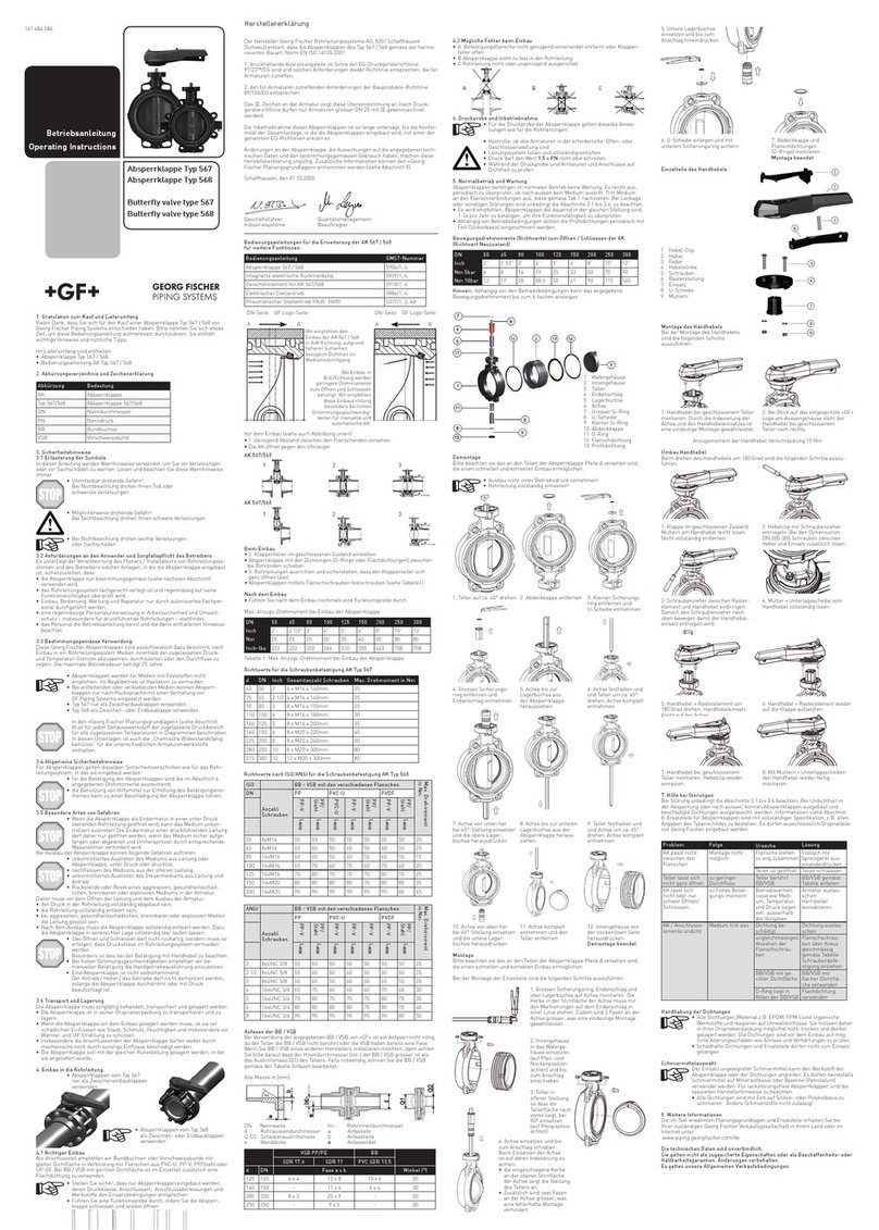
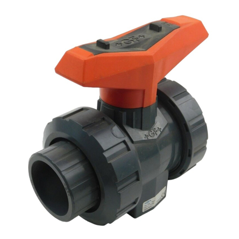
Georg Fischer Piping Systems 514 User manual

GF Piping Systems
Diaphragm valve
type 514, 515, 517, 519,
manually operated
Operating Instructions
Membranventil
Typ 514, 515, 517, 519,
handbetätigt
Betriebsanleitung
Robinet à membrane
types 514, 515, 517, 519,
à actionnement manuel
Manuel d'utilisation
Válvula de membrana
tipo 514, 515, 517, 519,
accionada manualmente
Manual de instrucciones
隔膜阀类型
514, 515, 517, 519
手动操作
操作说明书
2007153 Diaphragm Valve Type 514-519, manually operated
MA_00118 / DE EN FR ES ZH / 03 (07.22)
© Georg Fischer Piping Systems Ltd
CH-8201 Schahausen/Switzerland
+41 52 631 30 26/info.ps@georgfischer.com
www.gfps.com

Content
Diaphragm valve
type 514, 515, 517, 519 3
Membranventil
Typ 514, 515, 517, 519 33
Robinet à membrane
types 514, 515, 517, 519 63
Válvula de membrana
tipo 514, 515, 517, 519 93
隔膜阀类型
514, 515, 517, 519 123

GF Piping Systems
Diaphragm valve
type 514, 515, 517, 519
manually operated
Operating Instructions

GF Piping Systems
Translation of the original instruction manual
Disclaimer
The technical data are not binding. They neither constitute expressly warranted characteristics nor guaranteed properties nor a guaran-
teed durability. It is subject to modification. Our General Terms of Sale apply.

5
Operating Instructions Diaphragm valve type 514, 515, 517, 519
Table of contents
1 About this document 7
1.1 Other applicable documents 7
1.2 Symbols 7
1.3 Abbreviations 7
1.4 Terms used 7
2 Safety Information 8
2.1 Meaning of the signal words 8
2.2 Observe instruction manual 8
2.3 Safety and responsibility 8
2.4 Notes for service and operating personnel 9
3 Product description 10
3.1 Intended use 10
3.2 Use not in accordance with the intended use 10
3.3 EC-Declaration of conformity 10
3.4 Type overview 11
3.5 Construction 11
3.6 Identification 12
3.7 Technical Data 13
4 Installation 17
4.1 Preparation 17
4.2 Installation process 18
5 Putting into operation 20
5.1 Preparation 20
5.2 Pressure testing 20
6 Normal mode 21
6.1 Measures during operation 21
6.2 Optical position indicator 22

6
Operating InstructionsDiaphragm valve type 514, 515, 517, 519
6.3 Handwheel 22
7 Service 23
7.1 General 23
7.2 Removal and disassembly 23
7.3 Replacing the diaphragm 25
7.4 Replacing the Gaskets 27
8 Troubleshooting 30
9 Accessories and spare parts 31
9.1 Accessories 31

7
Operating Instructions Diaphragm valve type 514, 515, 517, 519
1 About this document
1.1 Other applicable documents
Document
GF Planning Fundamentals Industry 700671686
Data sheet www.gfps.com/is-manuals-valves
Chemical resistance www.gfps.com
These documents are available from the GF Piping Systems sales company or at www.gfps.com.
1.2 Symbols
Symbol Indication
• Listed in no particular order.
►Call for action: Here, something has to be done.
1. Call for action in a certain order: Here, something has to be done in the specified order.
1.3 Abbreviations
Abbreviation Indication
DN Nominal diameter
PN Nominal pressure
1.4 Terms used
Term Indication
Valve Diaphragm valve type 514, 515, 517, 519.
Medium Operating medium flowing through the valve.

8
Operating InstructionsDiaphragm valve type 514, 515, 517, 519
2 Safety Information
The safety instructions apply to use as described under "Intended use".
The safety instructions do not cover the following cases:
• Incidental events occurring during installation, operation and service.
• The operator is responsible for the local and site-related safety regulations.
2.1 Meaning of the signal words
In this instruction manual, warnings are used, which shall warn the user of death, injuries or material damage. Always read and
observe these warnings!
DANGER!
Imminent danger!
Non-observance may result in major injuries or death.
►Measures to avoid the danger.
WARNING!
Possible danger!
Non-observance may result in serious injuries.
►Measures to avoid the danger.
CAUTION!
Dangerous situation!
Non-observance may result in minor injuries.
►Measures to avoid the danger.
NOTE!
Dangerous situation!
Non-observance may result in material losses.
2.2 Observe instruction manual
The instruction manual is part of the product and an important element within the safety concept.
►Read and observe instruction manual.
►Always have instruction manual available with the product.
►Give instruction manual to all subsequent users of the product.
2.3 Safety and responsibility
►Only use the product as intended, see “Intended use“.
►Do not use a damaged or defective product. Replace any damaged product immediately.
►Make sure that the piping system has been installed professionally and that it is inspected regularly.
►The safety instructions for the valves are the same as for the piping system they are installed in.

9
Operating Instructions Diaphragm valve type 514, 515, 517, 519
2.4 Notes for service and operating personnel
The following target groups are addressed in these operating instructions:
Operators
Operators are instructed in the operation of the product and observe the safety guidelines.
Service personnel
The service personnel has professional technical training and performs installation, putting into operation, as well as maintenance
work.
DANGER!
Improper handling!
Incorrect installation, putting into operation or service can cause personal injury and damage to property, as well as endanger the
environment.
►Installation and putting into operation of product and accessories exclusively by persons who have the required training, know-
ledge or experience.
►Regular instruction of personnel in ll pplicble mtters of loclly pplicble regultions for occuptionl sfety nd environ-
mentl protection, especilly for pressurized pipes.
DANGER!
Use of hazardous and non-approved media!
Non-approved chemically aggressive or hot media can attack materials, cause personal injury and endanger the environment.
Components not in contact with the medium can be attacked by leakage inside the valve.
►Observe the safety data sheets or the applicable safety regulations for the media used.
►Check the compatibility of the valve materials with the medium.
►Do not use unapproved media.
►Regularly check the valve for wear and, if necessary, perform service.
►Wear appropriate protective equipment.
►For hot media: Work only on cooled down system.
►In case of uncertainty regarding approved media, contact the GF Piping Systems sales company.

10
Operating InstructionsDiaphragm valve type 514, 515, 517, 519
3 Product description
3.1 Intended use
Diaphragm valves type 514, 515, 517 and 519 are exclusively intended to be installed in a compatible industrial piping system to shut
o, pass or control the flow of approved media.
3.2 Use not in accordance with the intended use
Any use other than that described in the intended use is not in accordance with the intended use and is therefore not permitted. If
unsuitable products are installed or used in safety-relevant applications, unintended operating conditions may occur in the applica-
tion that can cause personal injury and/or property damage. Only use the product in safety-relevant applications if this use is ex-
pressly specified and permitted in the product documentation.
Georg Fischer Piping Systems Ltd. accepts no liability for damage resulting from improper use. The risks associated with improper
use lie solely with the user.
3.3 EC-Declaration of conformity
The manufacturer Georg Fischer Rohrleitungssysteme AG, 8201 Schahausen (Switzerland) declares that the industrial valves
listed below are pressure-maintaining equipment in the sense of the EC Pressure Equipment Directive 2014/68/EU, Category I,
Module A, according to the listed harmonized design standards, and comply with such requirements of this Directive as apply to
industrial valves. The CE marking on the industrial valves indicates this conformity.
According to the Pressure Equipment Directive (Art. 4, Par. 3), industrial valves whose DN is less than or equal to 25 may not bear
the CE marking. The putting into operation of these industrial valves is prohibited until the conformity of the entire system, in which
the industrial valves are installed, with the above-mentioned EC Directive has been declared.
Modifications which aect the stated technical data and the intended use render this declaration of conformity or manufacturer's
declaration invalid.
Additional information can be found in the "GF Planning Fundamentals Industry".
Product group Type designation Additional directives and harmonized de-
sign standards
Thermoplastic diaphragm valves 514, 515, 517, 519 EN ISO 16138
Schahausen, December 1, 2021
Bastian Lübke
Head of Global R&D
Georg Fischer Piping Systems Ltd.
CH-8201 Schahausen (Switzerland)

11
Operating Instructions Diaphragm valve type 514, 515, 517, 519
3.4 Type overview
Type 514
Radially removable
Type 515
Spigot variant
Type 517
Flange version
Type 519
Outlet valve
3.5 Construction
The design of the valve is identical for the four Valve body types, except for the connections.
2
1
3
4
5
6
8
9
10
7
11
Item Name
1 Hand wheel locking device
2 Handwheel
3 Housing nut
4 Inner housing
5 Spindle assembly incl. diaphragm holder
6 Thrust piece
7 Diaphragm
8 Valve body
9 Insert
10 Union nut
11 Friction lock
Exemplary structure of diaphragm valve type 514.

12
Operating InstructionsDiaphragm valve type 514, 515, 517, 519
3.6 Identification
3.6.1 Laser engraved label
PVC-UEPDM
PN10
Type 514 1 1/4“ DN32
0 00000000
Made in Switzerland
1
2
3 4
5
6
7
Item Name
1Designation type
2Nominal pressure
3Dimension
4Diaphragm material
5Valve body material
6Serial number
7CE marking
3.6.2 Label sticker
161514015
PVC-U EPDM PN10
0000000
Type 514
1
4
2
3
7
6
5
Item Name
1Designation type
2Order number
3Valve body material
4Diaphragm material
5Serial number
6Nominal pressure
7CE marking
3.6.3 Diaphragm material identifying feature
1
Item Name
1Friction lock
The color of the friction lock on the Valve body indicates the diaphragm material.
Friction lock
Color
Diaphragm material O-ring*
Black EPDM EPDM
White PTFE/EPDM FKM
Green PTFE/FKM FKM
Red FKM FKM
Blue NBR EPDM
*for type 514

13
Operating Instructions Diaphragm valve type 514, 515, 517, 519
3.7 Technical Data
3.7.1 Specifications
Specifications
Allowed medium Liquid and gaseous medium which do not negatively aect the physical and chemical properties of the
respective housing and diaphragm material during normal mode.
Information on chemical resistance is available from the GF Piping Systems sales company or at
www.gfps.com.
Dimensions Type 514 d16/DN10 – d63/DN50, ½” - 2”
Type 515 d16/DN10 – d63/DN50, ½” - 2”
Type 517 d16/DN10 – d63/DN50, ½” - 2”
Type 519 d16/DN10 – d20/DN15, ½”; d160/DN150 – d63/DN50, 4”- 2”
Materials Valve body Type 514 PVC-U, PVC-C, ABS, PP-H, PVDF, PVDF-HP
Type 515 PVC-U, PVC-C, ABS, PP-H, PP-N, PVDF, PVDF-HP
Type 517 PVC-U, PVC-C, PP-H, PVDF, PVDF-HP
Type 519 PP-H, PP-N, PVDF-HP
Housing nut PPGF30 for PN10
PPSGF40 for PN16 (only water applications)
Gaskets 1) Diaphragm NBR FKM EPDM PTFE
O-ring EPDM FKM EPDM FKM
Pressure levels PN10 PVC-U, PVC-C, ABS, PP-H, PP-N, PVDF, PVDF-HP
PN16 PVC-U, PVDF, PVDF-HP
(depending on insertion piece)
Operating temperature
2) (Valve body material)
PVC-U 0 to 60 °C
PVC-C 0 to 80 °C
ABS -30 to 60 °C
PP 0 to 80 °C
PVDF -20 to 140 °C
Actuation variants Manually operated
Pneumatic (see type DIASTAR)
Electrical (see type e-DIASTAR)
Connections Type 514 Screw connections with solvent cement sockets, threaded sockets, fusion
sockets, butt fusion nozzles
Type 515 Solvent cement spigot, socket fusion nozzles, butt fusion nozzles
Type 517 Fixed flange 3), backing flange
Type 519 3-way valve with butt fusion nozzles
Approvals ACS, FDA, DIBt
1) Further combinations on request.
2) As per pressure-temperature diagram in data sheet. There may be a deviation of the temperature range depending on the seal
material combination.
3) Only JIS variant.

14
Operating InstructionsDiaphragm valve type 514, 515, 517, 519
3.7.2 Kv 100-values
Type 514 – 517
d
(mm)
DN
(mm)
Inch
(")
Kv 100
(l/min)
Cv 100
(US gal./min)
kv 100
(m3/h)
20 15 ½ 125 9 8
25 20 ¾ 271 19 16
32 25 1 481 33 29
40 32 1 ¼ 759 52 45
50 40 1 ½ 1263 87 76
63 50 2 1728 119 104
Type 519
d
(mm)
DN
(mm)
Inch
(")
Kv 100
(l/min)
Cv 100
(US gal./min)
kv 100
(m3/h)
20 15 ½ 57 4 3
25 20 ¾ 89 6 5
25 20 ¾ 118 8 7
32 25 1 80 6 5
32 25 1 105 7 6
32 25 1 231 16 14
40 32 1 ¼ 85 6 5
40 32 1 ¼ 119 8 7
40 32 1 ¼ 153 11 9
40 32 1 ¼ 187 13 11
50 40 1 ½ 86 6 5
50 40 1 ½ 160 11 10
50 40 1 ½ 206 14 12
50 40 1 ½ 524 36 31
50 40 1 ½ 667 46 40
63 50 2 84 6 5
63 50 2 150 11 9
63 50 2 184 13 11
63 50 2 471 32 28
63 50 2 610 42 37
63 50 2 747 52 45
90 80 3 82 6 5
90 80 3 103 7 6
90 80 3 129 9 8
90 80 3 623 43 37
90 80 3 696 48 42
110 100 4 78 5 4
110 100 4 103 7 6
110 100 4 131 9 8
110 100 4 604 42 36
110 100 4 661 46 40
140 125 5 146 10 9
140 125 5 382 26 23
140 125 5 440 30 26
140 125 5 502 35 30
160 150 6 139 10 8
160 150 6 382 26 23
160 150 6 436 30 26
160 150 6 498 34 30

15
Operating Instructions Diaphragm valve type 514, 515, 517, 519
3.7.3 Flow rate
Flow characteristics type 514–517
Flow characteristics type 519
x Open angle (%)
y Kv, Cv value (%)
0.0
10.0
20.0
30.0
40.0
50.0
60.0
70.0
80.0
90.0
100.0
0102030405060708090100
x
y
x Open angle (%)
y Kv, Cv value (%)
0.0
10.0
20.0
30.0
40.0
50.0
60.0
70.0
80.0
90.0
100.0
0102030405060708090100
x
y

16
Operating InstructionsDiaphragm valve type 514, 515, 517, 519
3.7.4 Pressure losses
Type 514 – 517
3.7.5 Operating torque
Type 514 – 517
0.001
0.01
0.1
1
110100 1'000 10'000
x [l/min]
y [bar]
d20
d25
d32
d40
d50
d63
x Flow rate
(l/min)
y pressure loss p
(bar)
30
25
20
15
10
5
0
15 20
Nominal diameter
DN [mm]
Type
514-517
PN10
PN16
Max. operating torque
y [Nm]
25 32 40 50

17
Operating Instructions Diaphragm valve type 514, 515, 517, 519
4 Installation
4.1 Preparation
DANGER!
Valve not suitable for application!
The valve has product-specific characteristics, installation dimensions and connections. The use of a valve unsuitable for the appli-
cation can cause personal injury and damage to property as well as endanger the environment.
►Check the compatibility of the valve materials with the medium.
►Match the dimensions of the piping system with the valve as per the type plate.
►Make sure that the pressure rating, type of connection, and connection dimensions correspond to the application conditions.
DANGER!
Uncontrolled evasion of the medium!
If the pressure in the piping system has not been completely relieved, the medium can escape in an uncontrolled manner. Depending
on the type of medium, risk of injury may exist.
►Completely relieve pressure in the pipe before opening.
►In case of harmful, inflammable, hot or explosive medium, completely empty and flush pipe. Possible residues must be taken
into account.
►Provide for safe collection of the medium by implementing appropriate measures (e.g. connection of a collection container).
►Drain the valve with the valve in the half-open position and collect the medium.
►Hazardous medium residues may remain in the valve despite drainage.
►Wear appropriate protective equipment.
NOTE!
Incorrect storage and transport!
Improper handling can impair the functional properties and quality of the product.
►Store and transport in unopened original packing.
►Protection against harmful physical influences such as light, dust, heat, moisture, UV radiation and mechanical influences.
►Storage in open position (delivery condition).
►Inspect for general damage before installation.
►Do not remove from the original packing until immediately before installation.
►Valves with an identifiable malfunction must not be installed.

18
Operating InstructionsDiaphragm valve type 514, 515, 517, 519
4.2 Installation process
►Always install the valve in the open position.
DANGER!
Use of hazardous and non-approved media!
Non-approved chemically aggressive or hot media can attack materials, cause personal injury and endanger the environment.
Components not in contact with the medium can be attacked by leakage inside the valve.
►Observe the safety data sheets or the applicable safety regulations for the media used.
►Check the compatibility of the valve materials with the medium.
►Do not use unapproved media.
►Regularly check the valve for wear and, if necessary, perform service.
►Wear appropriate protective equipment.
►For hot media: Work only on cooled down system.
►In case of uncertainty regarding approved media, contact the GF Piping Systems sales company.
CAUTION!
Thermal expansion forces on piping system!
Preventing thermal expansion during temperature changes results in axial or bending forces. Piping system and valve may be da-
maged.
►Make sure that the forces are absorbed by suitable fixed points before or behind the valve.
CAUTION!
Damage due to increased Operating torque!
Risk of injury and/or damage to property due to the use of non-designated aids to increase the Operating torque.
►Operate the valve only with the intended actuating means (lever, transmission and actuator) according to the Operating torque
specified in the technical documentation.
►Mount the valve as a fixed point, or fasten the associated pipe directly upstream and downstream of the valve with associated
retainers.
►If increased Operating torque occurs, check valve for damage or wear.
CAUTION!
Pipe not in alignment!
Risk of injury and/or damage to property due to leakage of the piping system because of stress forces in the piping system.
►Make sure that the valve and pipe are aligned with each other.
4.2.1 Radially mountable and dismountable valve
All materials with Valve body type 514
1. Loosen the union nuts and slide them onto the intended pipe ends.
2. Depending on the type, cementing, screwing or fusing the connecting parts onto the pipe ends (see GF Planning Fundamentals
Industry - Glued/Fused connections).
3. Place the diaphragm valve between the connection parts.
4. Tighten the union nuts manually.
WARNING!
Tighten union nuts up to DN50 only hand-tight!
Risk of injury and/or material damage due to leaking liquids caused by overtightened or defective union nuts.
►Tighten union nuts up to DN50 only hand-tight, without auxiliary tools.
►Tighten the union nuts from DN50 with a strap wrench as per the tightening torque specified in the technical documentation.
4.2.2 Adhesive joint
PVC-U, PVC-C and ABS - Types 514, 515
Only join identical materials. After the curing time, flush the pipeline section with water without pressure (see chapter "Jointing
technology" in GF Planning Fundamentals Industry).

19
Operating Instructions Diaphragm valve type 514, 515, 517, 519
WARNING!
Connection of incompatible materials!
Risk of injury and/or damage to property due to leakage of the piping system because of connections of dierent, mutually incompa-
tible materials.
►Only identical materials may be joined together by means of fused and bonded joints.
►Pipeline sections with bonded joints must be flushed with water without pressure as soon as possible after the joints have been
completed.
4.2.3 Fused joint
PP-H, PP-N, PVDF, PVDF-HP - Types 514, 515, 519
Only join identical materials (see chapter "Jointing technology" in GF Planning Fundamentals Industry).
WARNING!
Connection of incompatible materials!
Risk of injury and/or damage to property due to leakage of the piping system because of connections of dierent, mutually incompa-
tible materials.
►Only identical materials may be joined together by means of fused and bonded joints.
►Pipeline sections with bonded joints must be flushed with water without pressure as soon as possible after the joints have been
completed.
4.2.4 Flange connection
All materials with Valve body type 517
For the tightening torques of the screws, refer to the relevant chapters of the GF Planning Fundamentals Industry.
CAUTION!
Leaking flange connection!
Danger of injury and/or material damage due to leaks in the piping system.
►Periodic check that no media escapes to the outside.
►If media is exiting at the flange connections, they have to be retightened.
CAUTION!
Contaminated jointing faces!
Risk of injury from contact with medium due to leaking connections.
►Protect jointing faces and connection parts from damage and poisoning, especially from hard or sharp-edged particles.

20
Operating InstructionsDiaphragm valve type 514, 515, 517, 519
5 Putting into operation
5.1 Preparation
1. Check that it is working: Close the valve and open it again.
2. Flush piping system.
5.2 Pressure testing
The same instructions apply to the pressure testing of valves as to the pipe (see chapter "Processing and installation" in GF Planning
Fundamentals Industry).
1. Check that all valves are in the required open or closed position.
2. Fill the line system with test medium and carefully vent it.
3. Build up test pressure.
4. The valves and connections should be checked for a tight seal during the pressure testing.
5. After the successful leak testing: remove the test medium.
6. Document your results.
DANGER!
Piping system not tight!
Leaky connections can cause medium to escape and cause property damage and personal injury, as well as endanger the environ-
ment.
►Check the tightness of the connections before putting into operation.
►Periodic check that no medium escapes to the outside.
►Wear appropriate protective equipment.
DANGER!
Pressure too high!
Exceeding the maximum permissible pressure can damage the piping system, causing medium to escape and cause property dama-
ge and personal injury, as well as endangering the environment.
►The component of the piping system with the lowest PN determines the maximum allowable test pressure in the piping section.
►Take measures to prevent pressure surges.
►Wear appropriate protective equipment.
CAUTION!
Maximum permissible test pressure!
For the pressure test of valves in open position, the same instructions apply as for the piping system (max. 1.5 x PN, und max. PN +
5 bar), but the test pressure in closed valve position must not exceed max. 1.1 x PN.
►For detailed information, see the Georg Fischer Planning Fundamentals.
►After successful pressure test: Remove test medium.
►Record the results.
This manual suits for next models
3
Table of contents
Languages:
Other Georg Fischer Piping Systems Control Unit manuals