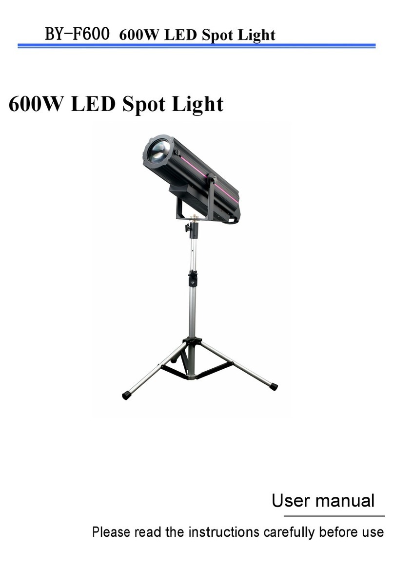
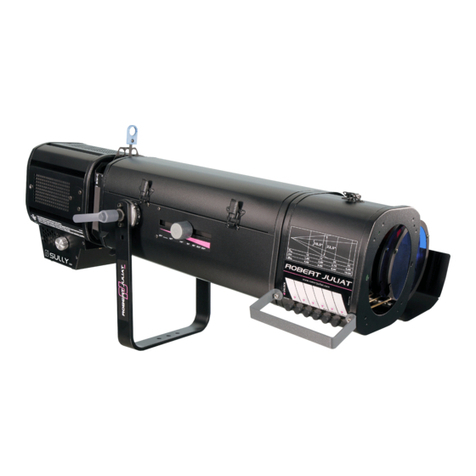
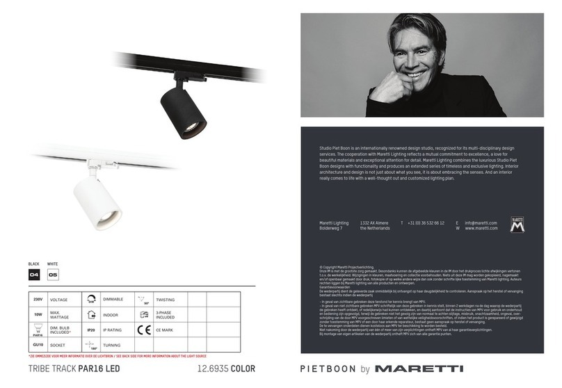
Eurosep Instruments G2L Series User manual

EUROSEP
Instruments
Spotlight G2L Serie
LED Framing Projector
1. Important Points
1.1. The framing projector must be installed in a compatible 2/3 circuit track adaptor, stable and
securely fastened, away from any source of heat or strong magnetic fields.
1.2. The 2/3 circuit track must be connected to a mains voltage between 2 -24 V / 5 -6 Hz. If
the framing projector is permanently connected, it is advisable to install a switch or circuit breaker
in the vicinity.
1.3. Never operate the framing projector when the installation instructions are not followed (see
paragraph 4).
1.4. Never disassemble the optical module nor
the 2/3 circuit track adaptor.
.
Before any handling or operation with the framing projector, it is essential
to take note of the following points:
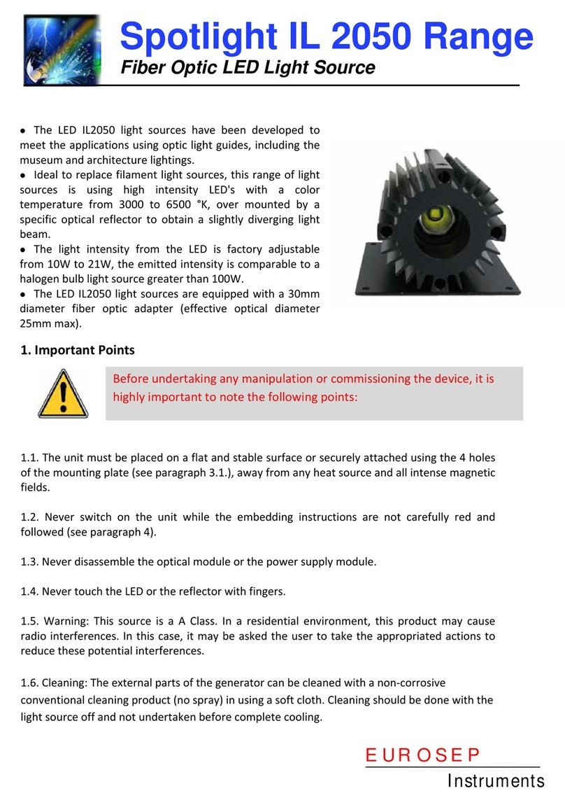
The LED G2L series framing projector has been
developed to meet the particular needs of
museums and architecture.
Ideal for replacing incandescent light sources,
this range of framing projectors uses a 16W LED
module with a color temperature of 3 °K
(warm white) and 4 °K (neutral white), high
intensity, with typical CRI (Ra) and red rendering
(R9) indexes of 95 and 9 respectively.
The luminous flux is manually adjustable from
2 to 1 %, the emitted intensity is equivalent
to a light system equipped with a 1 W halogen
bulb.
An elaborate optical system (see picture) provides an
excellent homogeneity, framing being adjusted by 4 quick
positioning framing shutters.
The optical body, made of aluminum (white or black), allows
an efficient passive cooling without any need of a forced
cooling.
The light emitted from the LED module covers the spectrum
from 4 to 7 nm with no emission in the ultraviolet nor in
the infrared.
Power is supplied directly from the mains 23 V/5 Hz via a 2/3-circuit track adaptor.
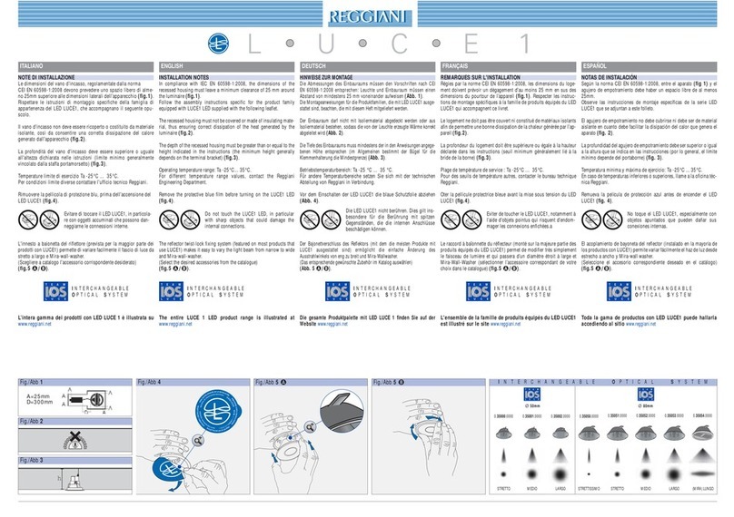
The projector has a vertical adjustment range of 2 ° and a horizontal adjustment range of 36 ° in
azimuth
.

1.5. Warning: This framing projector is a Class A device. In a residential environment, this device
may cause low radio interferences. In this case, the user may be required to take appropriate
measures to remedy any potential interference.
1.6. Cleaning: The outside of the framing projector can be cleaned with a non-corrosive
conventional cleaning product without spray and apply with a soft cloth. The cleaning must be
done light source off, the whole set back completely at room temperature.
2. Warranty Conditions
EUROSEP Instruments warrants the full system for a period of 2 years from the date of
delivery, when used strictly in accordance with the attached directives of use.
This warranty is strictly limited to repairing or replacing of the damaged product. To enjoy full
warranty, the purchaser commits himself to justify his demand by a written request. Also, he has
to give to EUROSEP Instruments all his support in order to notice and repair the damages. He
should avoid repairing the unit by himself or by someone else unless he got a written agreement
from EUROSEP Instruments.
All warranties are excluded for proximate, incidental or consequential damages, negligence, lack
of supervision or maintenance, use in non-conformity with the instruction manual directives and
replacement or repair due to a fair wear.
EUROSEP Instruments shall in no event be held liable for any damage caused by products supplied
by it.
Prior operation, it is essential to take note of the "Important Points" described in paragraph 1.
3. Description of the Framing Projector
The optical module and the 2/3 circuit track adaptor surfaces can be hot
during operation. Before undertaking any manipulation, wait for their
complete cooling.
Optical Module
2/3 Circuit Track Adaptor
Shutter
M5 fixing screws
Lens
Light intensity
adjustment knob
System
to hang the
optical module
2 M5
butterfly
screws
Rails

4. Operation
4.1. 2/3 circ it track adaptor installation
•Insert the 2 tooth lock washers on
the threated shaft of the optical module (1),
•Take the 2/3 circuit track module,
slightly spread the 2 arms of its
support and position each of them in
the threated shaft,
•Screw the 2 butterfly screws (2).
•Connect the cable on the rear part of the
optical module.
4.2. Installation into the 2/3 circ it track
•Slide the 2/3 circuit track module into a compatible
circuit track (3),
•Pull the trigger to fix the position (3),
•Turn the rotary knob to the correct
position to ignite (3).
4.3. L mino s intensity adj stment
•The potentiometer located on the 2/3
circuit track module allows the light
intensity to be adjusted between 2 and
1 % (3).
4.4. Optical adj stment
•Adjust by screwing/unscrewing the front
lens until to get a perfect focusing of the
image (4).
5. Technical Characteristics
5.1. Main S pply
Main supply 2 - 24 VAC
Frequency 5 - 6 Hz
Number of phase 1
Input wattage From 5 à 2 W (depending of the
light intensity)
5.3. Optical
Bandwidth 4 à 7 nm
LED Wattage 16 W
CRI (Color Rendering Index) 95 typical
1
2
5.2. General
Operating temperature +1 / +4 °C
Max. relative humidity 95%
Protection indice IP2
Dimensions 27 x11 x26 mm
Total weight 1,5 kg
4.5. Sh tter adj stment
•To adjust the framing, pull/push the
4 shutters (4),
•To lock/unlock the shutter rotation,
use the clamping screw.
4
3
Trigger
Rotary knob
Potentiometer
4
shutters
Front lens
Clamping screw

5.4. Range of Framing Projector
* Light Intensity measured at 3m from the framing projector..
Manufacturer Name EUROSEP Instruments
Address ZI STELYTEC
424 SAINT CHAMOND (France)
We, EUROSEP Instruments, declare under our sole responsibility that the products named here-after :
Product Description : LED FRAMING PROJECTOR
Part Number : PRSPG2XXXL
comply with requirements of following European Directives :
RoHS Directive : 2 11/65/UE from 8/ 6/2 11
EMC Directive : 2 14/3 /UE from 26/ 2/2 14
Safety Directive : 2 14/35/UE from 26/ 2/2 14
Product’s compliance has been assessed in conformity with the relevant Union harmonization legislation,
by applying following standards :
Low Voltage Safety
EN 60598-1 (2015) + EN60598-2-1 (1991) + EN 60598-2-5 (2016)
Electromagnetic Emissions
EN 55015 (2014)
EN 61000-3-2 (2014) Classe A
EN 61000-3-3 (2014)
Electromagnetic Imm nity
EN 61000-4-2 (2009), 4-3 (2006 + A1-2008 + A2-2011), 4-4 (2013), 4-5 (2014),
4-6 (2014), 4-8 (2010), 4-11 (2004)
EN 61547 (2009)
Saint Chamond, August 1st, 2 17.
Thomas MONTICO
President
Non-binding document, subject to change without notice. All trademarks are the property of their respective manufacturer.
Copyright@ August 2 17 - EUROSEP Instruments – PRSPG2L.D1.1A
Part Number Color Temp. (°K) Lux/3m* Body Color Aperture
PRSPG2324L 3 495 Black / White
24°
PRSPG234 L 3 18 Black / White
4 °
PRSPG2424L 4 55 Black / White
24°
PRSPG244 L 4 2 Black / White
4 °
EU
DECLARATION
OF
CONFORMIT
Y
EUROSEP
Instruments
BP 38233 Cergy Saint Christophe
F-95800 Cergy Pontoise Cedex (Fran e)
Tél : 33 (0)1 3422 9522 - Fax : 33 (0)1 3422 9532
E-mail : eurosep@eurosep. om - Internet http://www.eurosep. om
This manual suits for next models
4
Other Eurosep Instruments Spotlight manuals
