Eurotech PROTEUS User manual

Rev 3.0 - April 2009 - ETH_PROTEUS_USM
USER MANUALI
PROTEUS
SINGLE BOARD COMPUTER
DIGITAL TECHNOLOGIES FOR A BETTER WORLD
www.eurotech.com

DISCLAIMER
The information in this document is subject to change without notice and should not be construed as a commitment
by any Eurotech company. While reasonable precautions have been taken, Eurotech assumes no responsibility for
any error that may appear in this document.
WARRANTY
This product is supplied with a 3 year limited warranty. The product warranty covers failure of any Eurotech
manufactured product caused by manufacturing defects. The warranty on all third party manufactured products
utilised by Eurotech is limited to 1 year. Eurotech will make all reasonable effort to repair the product or replace it
with an identical variant. Eurotech reserves the right to replace the returned product with an alternative variant or
an equivalent fit, form and functional product. Delivery charges will apply to all returned products. Please check
www.eurotech.com for information about Product Return Forms.
TRADEMARKS
Eurotech® is a registered trademark of Eurotech, Inc. Catalyst™ is a trademark of Eurotech, Inc. All other product
or service names are property of their respective owners.
All other trademarks recognised.
REVISION HISTORY
Issue no. PCB Date Comments
A1st October 2008 First full release of Manual.
B 18th December 2008 New connectors section and minor updates.
C 2nd April 2009 Minor updates and new branding.
© 2009 Eurotech.
For contact details, see page 75.

Contents
Issue C 3
Contents
Handling your board safely.......................................................................................................5
Conventions..............................................................................................................................5
Introduction...............................................................................................................................6
Features of standalone variants ...............................................................................................7
Features of COM Express variants.........................................................................................10
Comparison of PROTEUS variants ........................................................................................13
Power consumption ................................................................................................................16
Support products ....................................................................................................................17
Getting started with your PROTEUS ......................................................................................20
What do need? ...........................................................................................................20
Connecting your PROTEUS .......................................................................................20
Identifying your PROTEUS.........................................................................................21
Connecting a SATA hard disk .....................................................................................21
Connecting a CD-ROM...............................................................................................21
Connecting a keyboard...............................................................................................22
Connecting a mouse...................................................................................................22
Turning on/off your PROTEUS ...................................................................................22
Using the serial interface (RS232)..............................................................................22
Using the audio features.............................................................................................22
Using the on board FLASH.........................................................................................22
Using the USB ports ...................................................................................................23
Using Ethernet interface .............................................................................................23
Using the flat panel interface ......................................................................................23
Using the backlight connector ....................................................................................24
Using the touchscreen interface .................................................................................24
Using the PCIE minicard sockets ...............................................................................24
Using the micro SD.....................................................................................................24
Using the general purpose inputs/outputs (GPIO)......................................................25
Using the GPS............................................................................................................25
Using the ZigBee (optional) ........................................................................................25
Using the Bluetooth (optional) ....................................................................................25
Software specification.............................................................................................................26
Operating system support ..........................................................................................26
Drivers ........................................................................................................................26
BIOS ...........................................................................................................................26
Hardware implementation.......................................................................................................27
COM Express specification ........................................................................................27
Type 1 module pinout feature set ...............................................................................27
Power .........................................................................................................................28
Block diagram.............................................................................................................29
Layout and dimensions...............................................................................................31
COM Express Type 1 carrier board expansion...........................................................33
Processor and chipset ................................................................................................33
US15W System Controller Hub ..................................................................................33
Graphics support ........................................................................................................34

PROTEUS user manual
Issue C
4
Bandwidth limitations ................................................................................................. 34
Main memory ............................................................................................................. 34
BIOS ROM memory................................................................................................... 34
Clock generation........................................................................................................ 35
Trusted platform module ............................................................................................ 35
Intel HD Audio............................................................................................................ 35
USB ........................................................................................................................... 35
PCI Express interface ................................................................................................ 36
PCI Express Mini Card............................................................................................... 36
Ethernet ..................................................................................................................... 36
Serial ATA .................................................................................................................. 37
Solid state hard disk................................................................................................... 37
LPC............................................................................................................................ 37
RTC............................................................................................................................ 37
Serial ports................................................................................................................. 37
GPS receiver (Build option) ....................................................................................... 38
Bluetooth (Build option) ............................................................................................. 38
ZigBee (Build option) ................................................................................................. 38
GPIO.......................................................................................................................... 38
Touch screen ............................................................................................................. 38
SMBus ....................................................................................................................... 38
Micro SD socket......................................................................................................... 39
Module power supply................................................................................................. 39
Indicator LEDs ........................................................................................................... 39
Connectors and LEDs............................................................................................................ 40
Connectors ................................................................................................................ 43
LEDs .......................................................................................................................... 65
GPIO mapping ....................................................................................................................... 68
Appendix A – Reference information...................................................................................... 72
Appendix B – RoHS Compliance ........................................................................................... 73
Eurotech Group Worldwide presence .................................................................................... 75
Handling your board safely
Issue C 5
Handling your board safely
Anti-static handling
This board contains CMOS devices that could be damaged in the event of static
electricity being discharged through them. At all times, please observe anti-static
precautions when handling the board. This includes storing the board in appropriate anti-
static packaging and wearing a wrist strap when handling the board.
Battery
The board contains a lithium non-rechargeable battery. Do not short circuit the battery or
place on a metal surface where the battery terminals could be shorted. When disposing
of the board or battery, take appropriate care. Do not incinerate, crush or otherwise
damage the battery. Use only standard CR1220 button batteries.
Packaging
Please ensure that, should a board need to be returned to Eurotech, it is adequately
packed, preferably in the original packing material.
Electromagnetic compatibility (EMC)
The PROTEUS is classified as a component with regard to the European Community
EMC regulations and it is the user’s responsibility to ensure that systems using the board
are compliant with the appropriate EMC standards.
Ro RoHS compliance
The European RoHS Directive (Restriction on the use of certain Hazardous Substances –
Directive 2002/95/EC) limits the amount of 6 specific substances within the composition
of the product.
A full RoHS Compliance Materials Declaration Form for the PROTEUS is included as
Appendix B – RoHS Compliance, page 73. Further information regarding RoHS
compliance is available on the Eurotech web site at www.eurotech.com.
Conventions
The following symbols are used in this guide:
Symbol Explanation
Note - information that requires your attention.
Caution – proceeding with a course of action may damage
your equipment or result in loss of data.

PROTEUS user manual
Issue C
6
Introduction
The PROTEUS is a single board computer primarily based on the Type-1 COM Express
extended format CPU module. It also has a secondary build option which allows it to
operate in a standalone (base-board free) operating mode.
The module provides the capability to support a combination of wireless standards
including:
•802.11a/b/g/n.
•Bluetooth.
•ZigBee.
•WiMAX.
•Cellular options including (EV-DO, HSUPA, HSDPA, UMTS, EDGE, GPRS, GSM).
•Support for a SiRFStar III based GPS module.
It also provides limited IO functionality including USB, LVDS, SATA and a resistive touch
screen interface.
For applications requiring functionality beyond that provided by the standalone module a
COM Express connector supporting PCI Express, LPC, USB, HD Audio, Gigabit Ethernet
and SMBus interfaces is provided to allow expansion onto a carrier board.
The board is able to run all x86 operating systems including Windows XP/
XP Embedded, Vista, CE and Linux.
The PROTEUS board can currently be purchased in the following variants:
•PROTEUS-COM-1.6-M1G-F2G fitted with 1.6GHz Intel Atom Z530 Processor,
US15W SCH, 1GB DDRII, 2GB FLASH and COM Express connector.
•PROTEUS-COM-1.6-M1G-F2G-GPS fitted with 1.6GHz Intel Atom Z530 Processor,
US15W SCH, 1GB DDRII, 2GB FLASH, GPS and COM Express connector.
•PROTEUS-1.6-M1G-F2G fitted with 1.6GHz Intel Atom Z530 Processor, US15W
SCH, 1GB DDRII, 2GB FLASH and standalone configuration.
•PROTEUS-1.6-M1G-F2G-GPS fitted with 1.6GHz Intel Atom Z530 Processor,
US15W SCH, 1GB DDRII, 2GB FLASH, GPS and standalone configuration.
For different board configuration contact our sales department.
Features of standalone variants
Issue C 7
Features of standalone variants
Processor
•Intel®Atom™ processor options:
Z530 Processor 1.6GHz TDP: 2.3W, or
Z510 Processor 1.1GHz TDP: 2.0W.
Chipset
•Intel US15W chipset TDP: 2.3W.
System memory
•DDR2 SDRAM (up to 1GB 400/533MHz).
Supported OS
•Windows XP, XP Embedded, CE.
•Embedded Linux.
BIOS
•Insyde H20 BIOS - EFI and legacy support.
•SPI Flash (proprietary interface).
On board flash
•Up to 4GB parallel ATA Thunderbolt Flash on board (2GB default).
Graphics
•Ultra low power integrated 3D Graphics.
•Two single-channel LVDS 24-bit interfaced to two connectors.
•One backlight connector.
PROTEUS V1I1 only supports one single-channel LVDS interface on the LVDS A
connector.
Audio
•HD Audio CODEC and 2W audio amplifier supporting stereo speakers, line in,
microphone and headphone.
Touch screen
•4, 5 and 8 wire resistive touch screen support.

PROTEUS user manual
Issue C
8
USB support
•USB 2.0 supporting low/full/high speed modes.
•Two ports connected to PCI Express MiniCard sockets.
•Two user accessible ports (Pin header, one client configurable).
•One port to board edge Type A connector.
•One port to ZIF connector.
Ethernet
•Gigabit Ethernet port supporting 10/100/1000 BaseT.
•Output to board edge RJ-45 connector.
Serial ATA
•One SATA connector.
•One power connector for SATA drive.
Serial ports
•One port used to connect to on-board GPS receiver OR ZIF connector (build option).
•One port used to connect to on-board Bluetooth module OR nanoZigBee OR ZIF
connector (build option).
•One port used to connect touch screen controller.
•One port used for general purpose RS232 TX/RX port.
PCI Express
•Two PCIe MiniCard sockets (one with SIM card slot).
SDIO/MMC
•One MicroSD socket.
•One 8 bit SD on ZIF connector.
GPIO
•Eight GPIO on header.
TPM
•Atmel Trusted Platform Module Device, TCG v1.2 compatible.
•SMBUS interface.
GPS receiver (build option)
•20-channel GPS receiver SirFStar III chipset module.
Bluetooth OR ZigBee (build option)
•Bluetooth wireless communication provided by on-board Bluetooth module.
•ZigBee interface provided by an on-board NanoZigBee module.

Features of standalone variants
Issue C 9
Test support
•JTAG Interface (Intel XDP).
Power requirements
•On-board voltage regulators and power management.
•Power / Sleep LED.
•+12V (optional: +5V standby, +3.3V battery).
•+8.5V DC to +24V DC (+12V nominal).
Physical/other
•155mm x 110mm x 17.8mm.
•Commercial temperature range: 0°C to +70°C.
•RoHS Directive: Lead-free.
PROTEUS user manual
Issue C
10
Features of COM Express variants
Processor
•Intel®Atom™ processor options:
Z530 Processor 1.6GHz TDP: 2.3W, or
Z510 Processor 1.1GHz TDP: 2.0W.
Chipset
•Intel US15W chipset TDP: 2.3W.
System memory
•DDR2 SDRAM (up to 1GB 400/533MHz).
Supported OS
•Windows XP, XP Embedded, CE.
•Embedded Linux.
BIOS
•Insyde H20 BIOS - EFI and legacy support.
•SPI Flash (proprietary interface).
On board flash
•Up to 4GB parallel ATA Thunderbolt Flash on board (2GB default).
Graphics
•Ultra low power integrated 3D Graphics.
•One single-channel LVDS 24-bit interface to COM Express.
•One single-channel LVDS 24-bit interface to connector.
PROTEUS V1I1 supports two single-channel LVDS interfaces on COM Express
connector and none on the Interface connector.
Audio
•HD Audio interface on board-to-board connector.
Touch screen
•4, 5 and 8 wire resistive touch screen support.

Features of COM Express variants
Issue C 11
USB support
•USB 2.0 supporting low/full/high speed modes.
•Two ports connected to PCI Express MiniCard socket.
•Two user accessible ports (Pin header, one client configurable).
•Four ports on board-to-board connector.
Ethernet
•Gigabit Ethernet port supporting 10/100/1000 BaseT.
•Output to board-to-board connector.
Serial ATA
•Two SATA outputs to board-to-board connector.
Serial Ports
•One port used to connect to on-board GPS receiver (build option).
•One port used to connect to on-board Bluetooth module OR nanoZigBee (build
option).
•One port used to connect touch screen controller.
•One port used for general purpose RS232 TX/RX port.
PCI Express
•Two PCIe MiniCard sockets connected to PCIE switch (one with a SIM card slot).
•Four PCIe to COM Express board-to-board connectors (One from chipset, three from
PCIE switch).
SDIO/MMC
•One MicroSD socket.
GPIO
•Eight GPIO on COM express connector.
•Eight GPIO on header
TPM
•Atmel Trusted Platform Module Device, TCG v1.2 compatible.
•SMBUS interface.
COM Express board-to-board connector
•Four PCI Express, LPC, four USB host, SMBus/I2C, HD Audio, one LVDS video
output, Gigabit Ethernet, two SATA, system and control, Power.
GPS receiver (build option)
•20-channel GPS receiver SirFStar III chipset module.

PROTEUS user manual
Issue C
12
Bluetooth OR ZigBee (build option)
•Bluetooth wireless communication provided by on-board Bluetooth module.
•ZigBee interface provided by an on-board NanoZigBee module.
Test support
•JTAG Interface (Intel XDP).
Power requirements
•On-board voltage regulators and power management.
•Power LED.
•+12V (optional: +5V standby, +3.3V battery).
Physical/other
•155mm x 110mm x 16.8mm.
•Commercial temperature range: 0°C to +70°C.
•RoHS Directive: Lead-free.
•COM Express connector Type 1, extended module mechanical footprint.

Comparison of PROTEUS variants
Issue C 13
Comparison of PROTEUS variants
Features COM Express Standalone
Processor Intel®Atom™ processor options:
Z530 processor 1.6GHz TDP: 2.3W.
Z510 processor 1.1GHz TDP: 2.0W.
99
Chipset Intel US15W chipset: US15W TDP: 2.3W. 99
Supported OS Windows XP, XP Embedded,CE, Embedded Linux. 99
Memory DDR2 SDRAM: up to 1GB (400/533MHz). 99
BIOS Insyde H20 BIOS - EFI and legacy support.
SPI Flash (proprietary interface). 99
Flash Up to 4GB parallel ATA Thunderbolt Flash on board. 2GB 2GB
Graphics Ultra low power integrated 3D graphics. 99
One single-channel LVDS 24-bit interface to COM
Express. One single-channel LVDS 24-bit interface to
connector
* (Note: for PROTEUS V1I1 see below)
98
Two single-channel LVDS 24-bit interface to two
connectors.
One backlight connector.
* (Note: for PROTEUS V1I1 see below)
89
PROTEUS V1I1
Two single-channel LVDS 24-bit interfaces to COM
Express.
98
PROTEUS V1I1
One single-channel LVDS 24-bit interface.
One backlight connector.
89
Audio HD Audio interface on board-to-board connector. 98
HD Audio CODEC and 2W audio amplifier supporting
two speakers, line in, mic in and headphone. 89
Touch Screen 4, 5 and 8 wire resistive touch screen support. 99
USB Support USB 2.0 supporting low/full/high speed modes.
Two ports connected to PCI Express MiniCard socket.
Two user accessible ports (Pin header, one client
configurable).
99
Four ports on board-to-board connector. 98
One port to board edge Type A connector.
One port to ZIF connector. 89

PROTEUS user manual
Issue C
14
Features COM Express Standalone
Ethernet Gigabit Ethernet port supporting 10/100/1000 BaseT. 99
Output to board-to-board connector. 98
Output to board edge RJ-45 connector. 89
Serial ATA Supports two SATA output to board-to-board connector. 98
Output to one SATA connector.
One power connector for SATA drive. 89
Serial ports One port used to connect to on-board GPS receiver or
ZIF connector Optional Optional
One port used to connect to on-board Bluetooth module
OR nanoZigBee OR ZIF connector (build options). Optional Optional
One port used to connect touch screen controller. 99
One port used for general purpose RS232 TX/RX port. 99
PCI Express Two x1 PCIe MiniCard sockets (from PCIE switch).
Four x1 PCIe to COM Express board-to-board
connector.(One from chipset, three from PCIE switch)
98
x1 PCIe MiniCard socket (from PCIE switch).
x1 PCIe MiniCard socket (from Poulsbo). 89
SDIO/MMC One MicroSD socket. 99
One 8 bit SD on ZIF connector. 89
GPIO Eight GPIO on COM express connector. 98
Eight GPIO on header. 99
TPM Atmel Trusted Platform Module Device, TCG v1.2
compatible
SMBUS interface.
99
COM Express
board-to-board
connector
Four PCI Express, LPC, four USB host, SMBus/I2C, HD
Audio, one LVDS video outputs, Gigabit Ethernet, two
SATA, system and control, Power.
98
GPS Receiver 20-channel GPS receiver SirFStar III chipset module. Optional Optional
Bluetooth OR
ZigBee (build
option)
Bluetooth wireless communication provided by on-board
WT11 Bluetooth module. Optional Optional
ZigBee interface provided by an on-board NanoZigBee
module. Optional Optional

Comparison of PROTEUS variants
Issue C 15
Features COM Express Standalone
Test Support JTAG Interface (Intel XDP). 99
On-board voltage regulators and power management.
Power / Sleep LED. 99
+12V (optional: +5V standby, +3.3V Battery). 98
+8.5V DC to +24V DC (+12V nominal). 89
Physical/other 155mm x 110mm.
Commercial: 0°C to +70°C
RoHS Directive: Lead-free
COM Express Extended module mechanical footprint.
99

PROTEUS user manual
Issue C
16
Power consumption
HW / SW
Board power – VIN
rail input voltage [V]
Board power – VIN
rail current [mA]
Total board
power [W] Note
Board only / XPe, idle 19.99 437.50 8.75
Board only / XPe, BurnIn test +
video 20.05 487.50
9.77 Board only
Board, 8.4" display with backlight,
keyboard, mouse, USB hub,
Ethernet / XPe, BurnIn + video
20.00 937.50
18.75 Standard,
no HDD
Board, 8.4" display with backlight,
keyboard, mouse, USB hub,
Ethernet, active hard disk drive /
XPe, BurnIn + video
19.84 1075.00
21.33 Standard,
with HDD
Board, 8.4" display with backlight,
Ethernet, active hard disk drive, 3x
full loaded USB (3x500mA), Wifi
card, GSM card / XPe, BurnIn +
video
19.95 1487.50
29.68 Heavy
loaded
S3 – sleep, board only / sleep
mode (suspend mode) 10.00 87.50 0.88 Board in
sleep

Support products
Issue C 17
Support products
The PROTEUS is supported by the following optional products:
•PROTEUS development kit. See below.
•PROTEUS ICE (Industrial Compact Enclosure). See below.
•Breakout boards. See the next page.
•LVDS to VGA adapter.
PROTEUS development kit:
PROTEUS ICE (Industrial Compact Enclosure):
PROTEUS user manual
Issue C
18
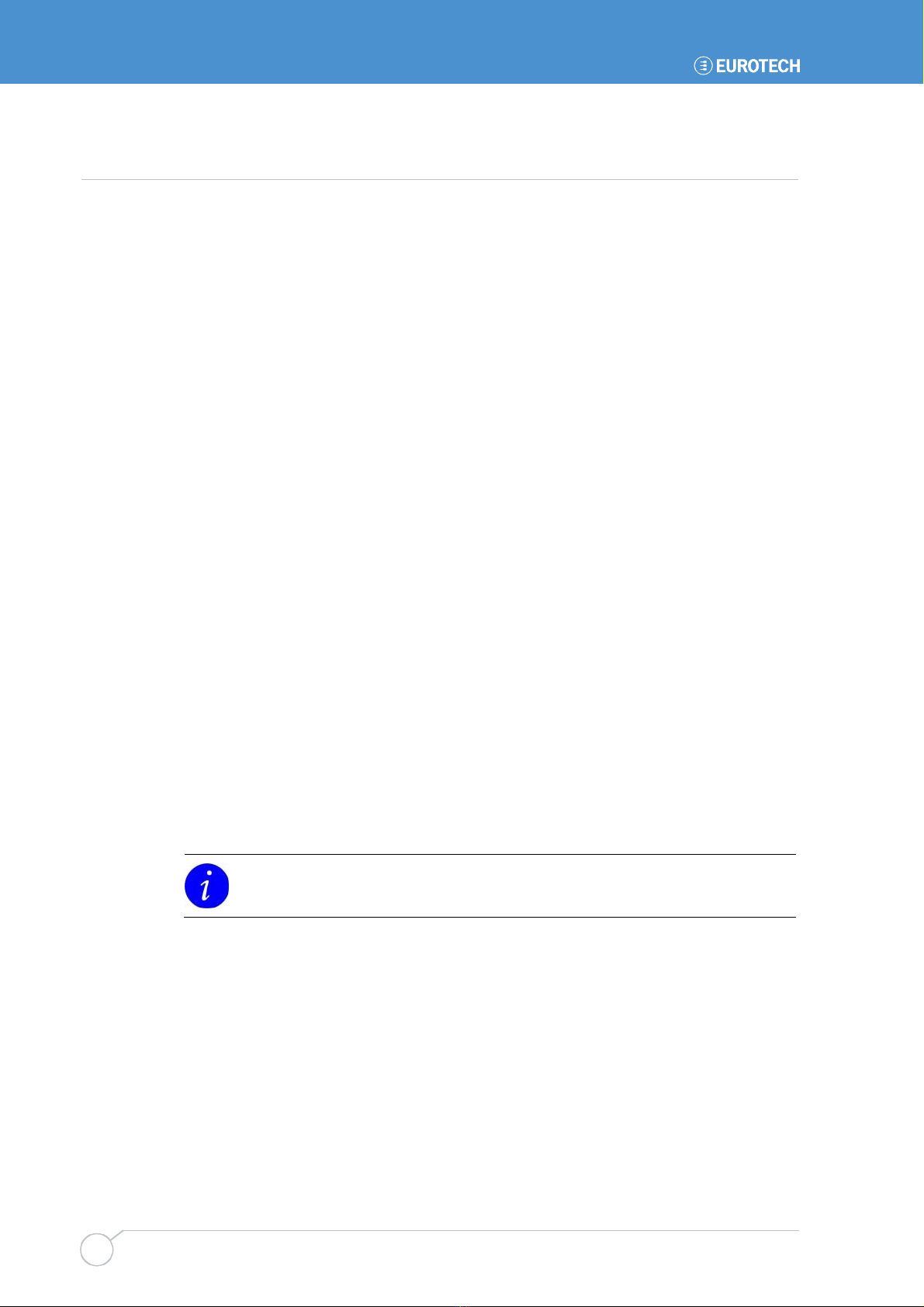
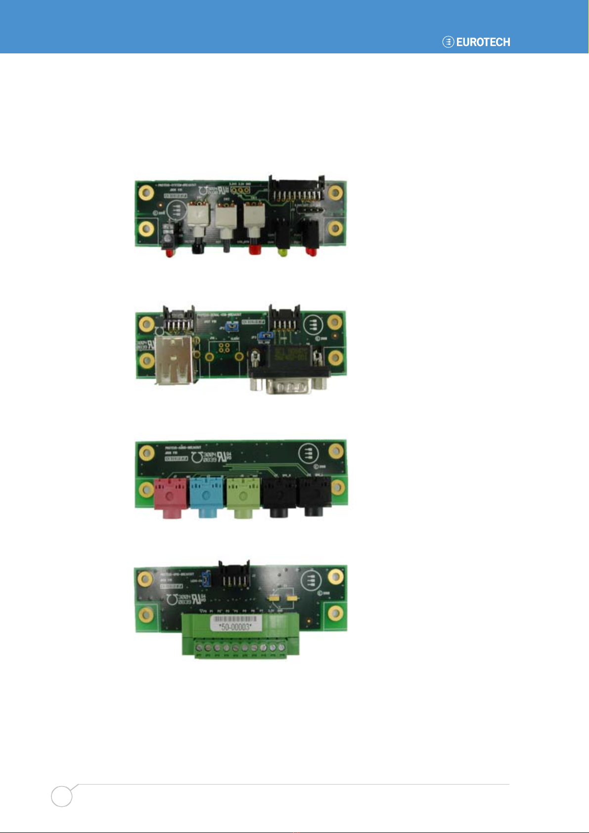
Breakout boards
Four breakout boards are available:
•System
Buttons (on/off, Reset, user button) and LEDs (power, HDD activity, PCIE minicards
activity, two user LEDs).
•USB and serial:
One DB9M RS232, one double USB A type connector
•Audio:
Mic input, line input, headphone, speaker jacks
•GPIO:
Eight general purpose input/output on screw terminal, eight line status LED

Support products
Issue C 19
LVDS to VGA adapter

PROTEUS user manual
Issue C
20
Getting started with your PROTEUS
What do need?
There are three basic configurations that can be used to access to your PROTEUS
board:
•PROTEUS board, TFT LCD display kit, keyboard/mouse, USB hub, and power.
•PROTEUS board, LVDS to VGA adapter, monitor, keyboard/mouse, USB hub, and
power.
•PROTEUS board with preinstalled remote access, Ethernet, and power.
Connecting your PROTEUS
PROTEUS stand alone configuration
1Connect display/adapter cable to LVDS A connector (J4).
2Connect USB hub to USB connector.
3Connect keyboard and mouse to the USB hub.
4Connect green power connector plug to a cable coming from a DC power supply. The
power supply output voltage should be between +8.5 to +24V (+12V nominal). Check
polarity.
5Switch on display/monitor power.
6Connect power cable to the PROTEUS board.
7Switch on power supply.
The board starts with the Eurotech logo splash screen. If a device with booting
capability is connected (or on board FLASH is preloaded with OS) then the board
boots from this, if not the BIOS screen is shown.
Table of contents
Other Eurotech Motherboard manuals

Eurotech
Eurotech ZEUS User manual

Eurotech
Eurotech VULCAN-533-M64-F16 User manual

Eurotech
Eurotech ALUDRA User manual

Eurotech
Eurotech GEMINI User manual

Eurotech
Eurotech AIM104-COM8 User manual

Eurotech
Eurotech GEMINI 1U ICE User manual

Eurotech
Eurotech PXA320 User manual

Eurotech
Eurotech ISIS-1.6-M1G-F2G-GPS User manual

Eurotech
Eurotech Bitsy G5 User manual

Eurotech
Eurotech BitsyXb User manual


