Eurotech AIM104-COM8 User manual

AIM104-COM8
8 Channel RS232
PC/104 Board
Technical Manual

AIM104-COM8 Technical Manual
ISO 9001
FM12961
Disclaimer
The information in this manual has been carefully checked and is believed to be accurate. Eurotech Ltd assumes no
responsibility for any infringements of patents or other rights of third parties, which may result from its use.
Eurotech Ltd assumes no responsibility for any inaccuracies that may be contained in this document. Eurotech Ltd makes
no commitment to update or keep current the information contained in this manual.
Eurotech Ltd reserves the right to make improvements to this document and/or product at any time and without notice.
Warranty
This product is supplied with a 3 year limited warranty. The product warranty covers failure of any Eurotech Ltd manufactured
product caused by manufacturing defects. The warranty on all third party manufactured products utilised by Eurotech Ltd is
limited to 1 year. Eurotech Ltd will make all reasonable effort to repair the product or replace it with an identical variant.
Eurotech Ltd reserves the right to replace the returned product with an alternative variant or an equivalent fit, form and
functional product. Delivery charges will apply to all returned products. Please check www.eurotech-ltd.co.uk for information
about Product Return Forms.
Trademarks
Windows NT, Windows 2000 and Windows XP are registered trademarks of the Microsoft Corporation.
All other trademarks recognised.
Revision History
Manual PCB Date Comments
Issue A V1.1 September 29th, 2004 First full release of manual.
Issue B V1.1 September 25th, 2006 Minor modifications.
Issue cV1.1 December 21st, 2007 Minor updates, Eurotech rebranding.
© 2007 Eurotech Ltd.
For contact details, see page 18.

AIM104-COM8 Technical Manual Contents
© 2007 Eurotech Ltd Issue C 3
Contents
Introduction........................................................................................................................................4
Handling your board safely....................................................................................................5
About this manual..............................................................................................................................6
Conventions...........................................................................................................................6
What items are provided?..................................................................................................................7
Getting started ...................................................................................................................................7
Unpacking and connecting up................................................................................................7
Description.........................................................................................................................................8
I/O map..............................................................................................................................................9
UART structure....................................................................................................................10
Interrupts..........................................................................................................................................11
Jumpers...........................................................................................................................................12
Default settings....................................................................................................................12
Cable connections ...........................................................................................................................17
Appendix A – Contacting Eurotech Ltd ............................................................................................18
Appendix B – Connector details.......................................................................................................19
Appendix C – Notes on using the 16C550 UART............................................................................21
Appendix D – RoHS-6 Compliance - Materials Declaration Form...................................................23
Index................................................................................................................................................24

AIM104-COM8 Technical Manual Introduction
© 2007 Eurotech Ltd Issue C 4
Introduction
The AIM104-COM8 is an 8-bit or 16-bit PC/104 module that provides up to eight
RS232 asynchronous communications channels.
Variants There is only one standard variant of the this board:
• AIM104-COM8: Eight channel RS232 PC/104 board.
A four channel version of the board may also be available for volume orders.
Please contact the Eurotech Ltd sales team for information on this variant.
Features
• Eight 16C550 compatible UART channels.
• Transfer rates up to 115.2Kbaud supported.
• +5V only operation.
• All channels can appear as a block anywhere in I/O address range 000-3FFh.
• First four channels can be individually set as standard PC/AT COM1-4.
• Each QUART (Quad-UART) can drive one link-selectable IRQ in the range 3, 4,
5, 7, 9, 10, 11, 12, 14, 15.
• The two QUART interrupts can be combined to drive one IRQ.
• PC/104 16 bit interface (but can be used in 8-bit slot if IRQ10, 11 and 15 are not
required).
• Zero wait state bus operation capability.
• Board access LED.
• Interrupt activity LED.
• TxD/RxD activity indicator LEDs on all channels.
• Power requirements: 220 mA (typical) at +5V DC.
• Temperature range: -20°C (-4°F) to +70°C (158°F) operating.
-40°C (-40°F) to +125°C (125°F) storage.

AIM104-COM8 Technical Manual Introduction
© 2007 Eurotech Ltd Issue C 5
Handling your board safely
Anti-static handling
This board contains CMOS devices. These could be damaged in the event of static
electricity being discharged through them. Observe anti-static precautions at all times
when handling circuit boards. This includes storing boards in appropriate anti-static
packaging and wearing a wrist strap when handling them.
Electromagnetic compatibility (EMC)
The AIM104-COM8 is classified as a ‘component’ with regard to the European
Community EMC regulations and it is the user’s responsibility to ensure that systems
using the board are compliant with the appropriate EMC standards.
The AIM104-COM8 has been designed to minimise noise emissions generated by the
high frequency host PC/104 system. It includes filter components on all serial I/O lines.
It is possible to capacitively couple the board ground to the chassis using metal pillars
and fastenings at the mounting hole marked ‘CHASSIS’. This is shown in the following
diagram:
Packaging Should a board need to be returned to Eurotech Ltd, please ensure that it is
adequately packed, preferably in the original packing material.
RoHS compliance
The European RoHS Directive (Restriction on the Use of Certain Hazardous
Substances – Directive 2002/95/EC) limits the amount of six specific substances within
the composition of the product. TheAIM104-COM8 is available as an RoHS-6
compliant option and is identified by an -R6 suffix in the product order code.A full
RoHS Compliance Materials Declaration Form is included in Appendix D – RoHS-6
Compliance - Materials Declaration Form, page 23. Further information about RoHS
compliance is available on the Eurotech Ltd web site: www.eurotech-ltd.co.uk
AIM104-COM8 Technical Manual About this manual
© 2007 Eurotech Ltd Issue C 6
About this manual
This manual describes the operation and use of the AIM104-COM8 PC/104 module.
It is both a reference and user manual and includes information about all aspects of the
module.
Conventions
Symbols
The following symbols are used in this guide:
Symbol Explanation
Note - information that requires your attention.
Tip - a handy hint that may provide a useful alternative or save
time.
Caution – proceeding with a course of action may damage
your equipment or result in loss of data.
Terminology
To prevent confusion with the standard PC AT nomenclature of COM1-4, this manual
refers to the channels on the AIM104-COM8 as 0-7. Where this manual specifies
COM1-4, this refers to the standard PCAT communications ports.

AIM104-COM8 Technical Manual What items are provided?
© 2007 Eurotech Ltd Issue C 7
What items are provided?
The AIM104-COM8 is supplied with the following items:
• The AIM104-COM8 board.
• Mounting kit.
Getting started
Unpacking and connecting up
To begin using the AIM104-COM8 board, follow these steps:
1Power down your computer.
2Install the board in a spare PCI slot.
3Power up your computer and install the appropriate driver available from our
website www.eurotech-ltd.co.uk/en/downloads.

AIM104-COM8 Technical Manual Description
© 2007 Eurotech Ltd Issue C 8
Description
The AIM104-COM8 uses two 16C550 type Quad-UART chips to provide eight standard
PC AT type serial channels which are supported by a wide range of third party software
and standard operating systems.
All channels are buffered to RS232 levels, supporting all the signals found on a PCAT
type 9-pin RS232 port.
The simplest I/O address mapping has the eight serial channels appearing as eight
bytes each, next to each other, based at any 16-byte boundary in the I/O map from
000-3FFh.
Channels 0-3 can be individually relocated at standard PCAT communications channel
addresses for COM1-4 respectively. See JP3 - Channel re-mapping to COM
addresses, page 15, for further details about address mapping.
Each QUART has its own interrupt line that can be linked to any of the following
PC/104 interrupts: IRQ3-5, 7, 9-12, 14-15.
The interrupt lines from the second QUART chips can be merged with the first to drive
a single IRQ line.
The AIM104-COM8 has a 16 bit PC/104 connector but utilises only interrupt lines
IRQ10, 11 12, 14 and 15 on the J5 connector. This means that the board can also be
used in an 8 bit PC/104 slot providing these interrupt lines are not required.
A further link on the AIM104-COM8 allows zero wait state operation of the PC/104 bus.
(This is dependant on the PC/104 CPU board supporting this option.)
AIM104-COM8 Technical Manual I/O map
© 2007 Eurotech Ltd Issue C 9
I/O map
The I/O mapping allows a flexible configuration to be achieved. At its simplest, the
UART’s appear as an array of eight contiguous ports with eight bytes for each UART.
The base address can be set at any 16-byte boundary.
Channels 0-3 can also be individually relocated at standard PC/AT communications
channel addresses for COM1-4 respectively. As this is done, these channels ‘disappear’
from the group until only the last four remain. When that happens, the board logic
knows that it has only 32 bytes in the group and so decodes those channels as a 32-
byte block.
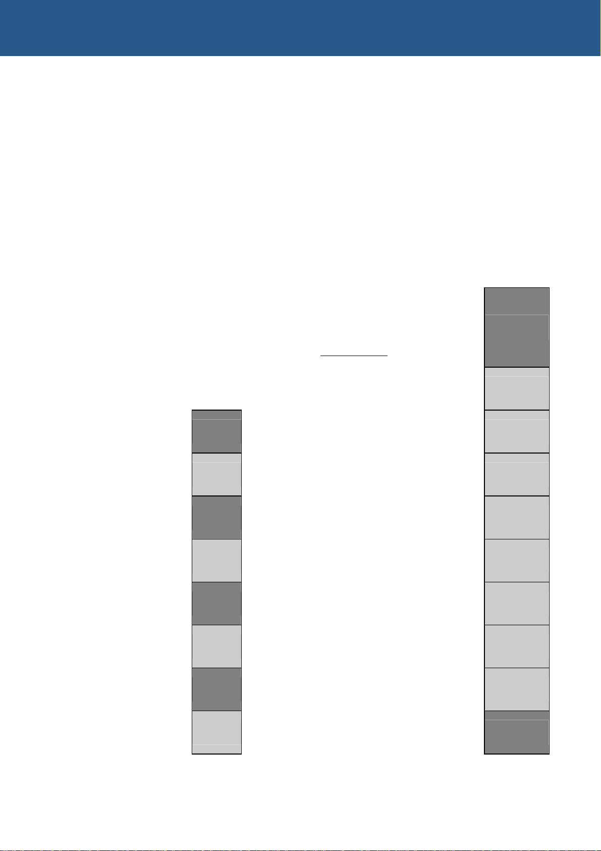
Group addressed map
000
...
base address
PC COM port locations
+00 Channel 0
000
... +08 Channel 1
02E8-2EF COM4 +10 Channel 2
+18 Channel 3
02F8-2FF COM2 +20 Channel 4
+28 Channel 5
03E8-3EF COM3 +30 Channel 6
+38 Channel 7
03F8-3FF COM1

AIM104-COM8 Technical Manual I/O map
© 2007 Eurotech Ltd Issue C 10
UART structure
Each channel occupies 8 bytes of I/O space with the following registers defined:
Offset Register Read Write
+0 RHR/THR Receive Holding Register Transmit Holding
Register
+1 IER Interrupt Enable Register
+2 ISR/FCR Interrupt Status Register FIFO Control Register
+3 LCR Line Control Register
+4 MCR Modem Control Register
+5 LSR Line Status Register
+6 MSR Modem Status Register
+7 SCR Scratchpad Register
General
Register Set
(DLAB [ICR:7] set)
+0 DLL LSB of Divisor Latch
+1 DLM MSB of Divisor Latch.
Baud Rate Register
(DLAB [ICR:7] clear)
If you are planning to write your own low level software for theAIM104-COM8, refer to
the datasheet for the Exar ST16C554 device. This is available to download from
www.exar.com.
You can also download some example C source code from www.eurotech-ltd.co.uk.

AIM104-COM8 Technical Manual Interrupts
© 2007 Eurotech Ltd Issue C 11
Interrupts
The first four channels drive one shared interrupt line and the last four channels drive
another. These IRQ lines can be selected from IRQ3, 4, 5, 7, 9, 10, 11, 12, 14, or 15.
IRQs 10, 11, 12, 14, and 15 are only available when the AIM104-COM8 is
used in a 16 bit PC/104 stack.
AIM104-COM8 Technical Manual Jumpers
© 2007 Eurotech Ltd Issue C 12
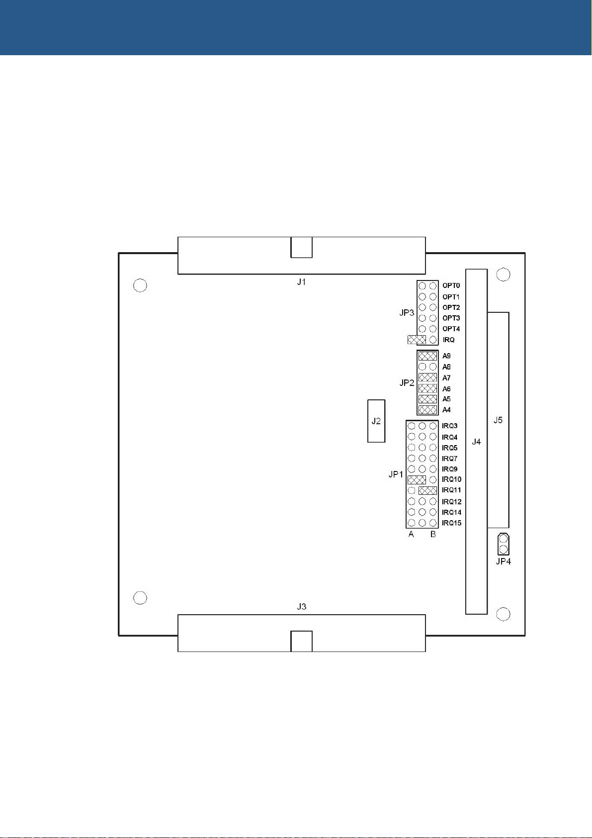
Jumpers
There are four user-selectable jumpers on theAIM104-COM8. These are used to
configure the I/O address and the interrupt line for each QUART.
Default settings
The default positions of the jumpers are as follows:
Refer to the documentation supplied with your CPU card to establish which spare I/O
and interrupt channels to use.
AIM104-COM8 Technical Manual Jumpers
© 2007 Eurotech Ltd Issue C 13
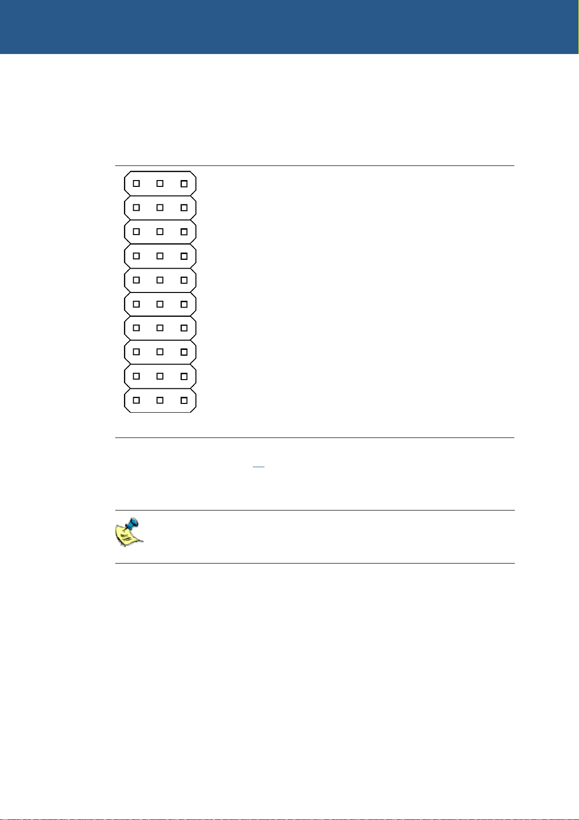
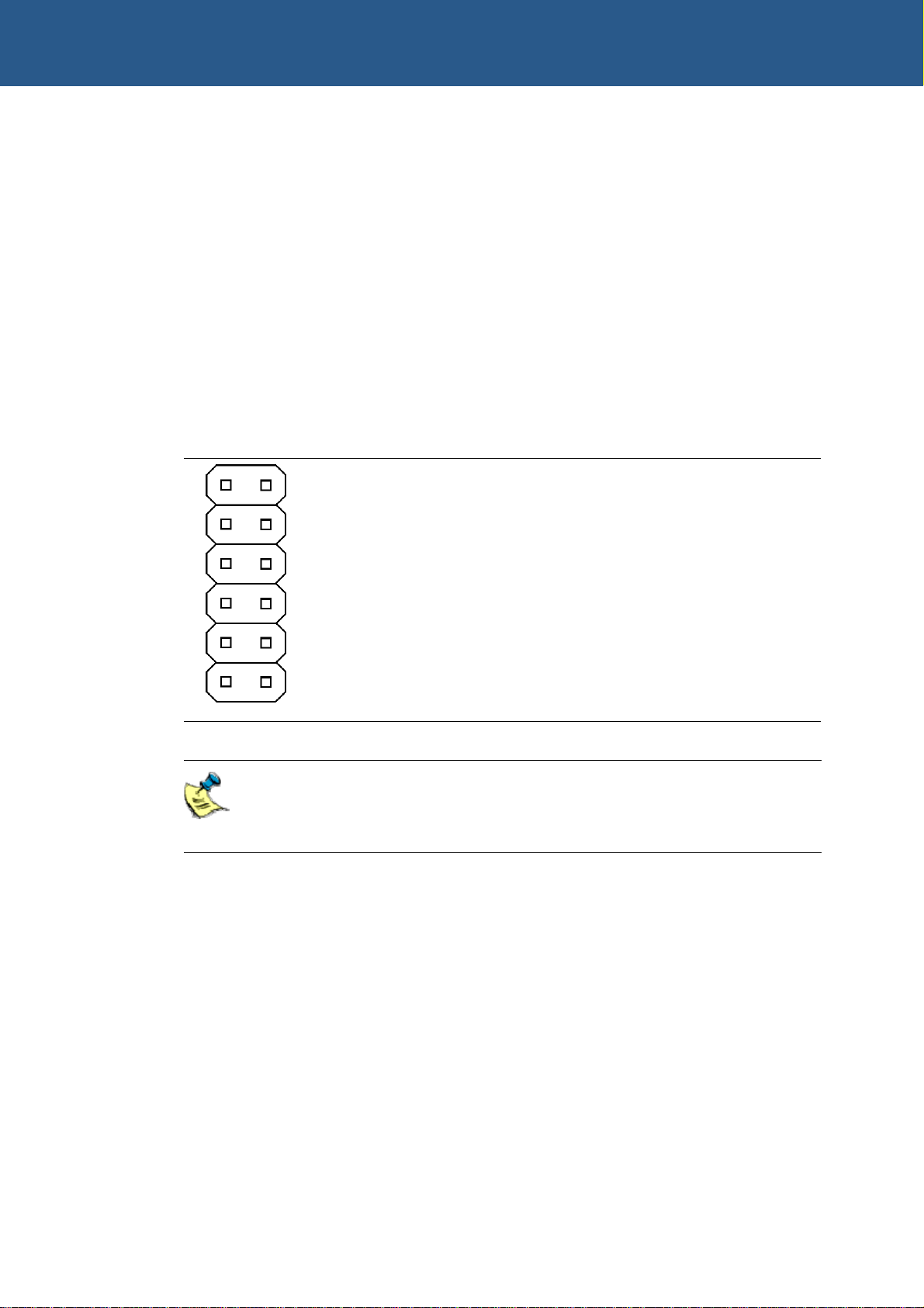
JP1 - Interrupt selection
The JP1 jumper is used to set the IRQ line for each group of four serial port channels.
The A position is used for channels 0-3 and the B position for channels 4-7.
JP1 Line Function when fitted
IRQ3 Routes IRQ line to IRQ3
IRQ4 Routes IRQ line to IRQ4
IRQ5 Routes IRQ line to IRQ5
IRQ7 Routes IRQ line to IRQ7
IRQ9 Routes IRQ line to IRQ9
IRQ10 Routes IRQ line to IRQ10
IRQ11 Routes IRQ line to IRQ11
IRQ12 Routes IRQ line to IRQ12
IRQ14 Routes IRQ line to IRQ14
IRQ15 Routes IRQ line to IRQ15
AB
When jumper JP3 (see page 15) is set to ‘IRQ’, sideA is for all channels and the signal
on side B becomes tri-stated so that it does not interrupt on both sides. In this case,
the link on side B should be removed.
Channels 0-3 share the same interrupt line, while 4-7 share another.
You cannot, for instance, set COM1/COM3 to use IRQ4 and COM2/COM4
to use IRQ3, which are the PC defaults.

AIM104-COM8 Technical Manual Jumpers
© 2007 Eurotech Ltd Issue C 14
JP2 - Group base address selection
The JP2 jumper is used to set the I/O base address for the serial ports. The default
jumper settings configure all of the serial ports at a 64-byte contiguous I/O space from
this address location.
The base address is always decoded to a 16-byte boundary. Fitting the link sets the
address line to zero for the decode. Leaving the link off means that the corresponding
address line must be a logic ‘1’ to select the board.
JP2 Line Function when fitted
A9 SetsA9 in I/O address decode to 0
A8 SetsA8 in I/O address decode to 0
A7 SetsA7 in I/O address decode to 0
A6 SetsA6 in I/O address decode to 0
A5 SetsA5 in I/O address decode to 0
A4 SetsA4 in I/O address decode to 0
The default base address is 0x100, to avoid conflicts with common PC I/O maps.
In order to achieve this fit all links apart fromA8. Check your system I/O map for
conflicts before use.
AIM104-COM8 Technical Manual Jumpers
© 2007 Eurotech Ltd Issue C 15
JP3 - Channel re-mapping to COM addresses
You can individually re-map channels 0 to 3 at the standard COM port addresses.
When these channels are mapped at COM ports they vanish from the group. This
prevents the host seeing them in two places.
If all four are mapped in that way, the group size falls to 32 bytes and channels 4 to 7
begin at the base address.
You should avoid addressing conflicts due to the group decoding overlapping COM
decoding. If there is a conflict, then the group decoding applies and any conflicting
COM decoded channel.
The decoding logic above ensures the minimum use of scarce I/O locations.
JP3 Line Function when fitted
OPT0 Channel 0 remapped to COM1
OPT1 Channel 1 remapped to COM2
OPT2 Channel 2 remapped to COM3
OPT3 Channel 3 remapped to COM4
OPT4 Disables I/O address decoding for channels 4 to 7
IRQ Combines interrupts from both quad-UART chips into
one (side Aon links below)
Interrupt merging: each quad-UART chip can assert an individual IRQ line,
but in systems where IRQ lines are scarce they can be combined into one
for both chips.
AIM104-COM8 Technical Manual Jumpers
© 2007 Eurotech Ltd Issue C 16
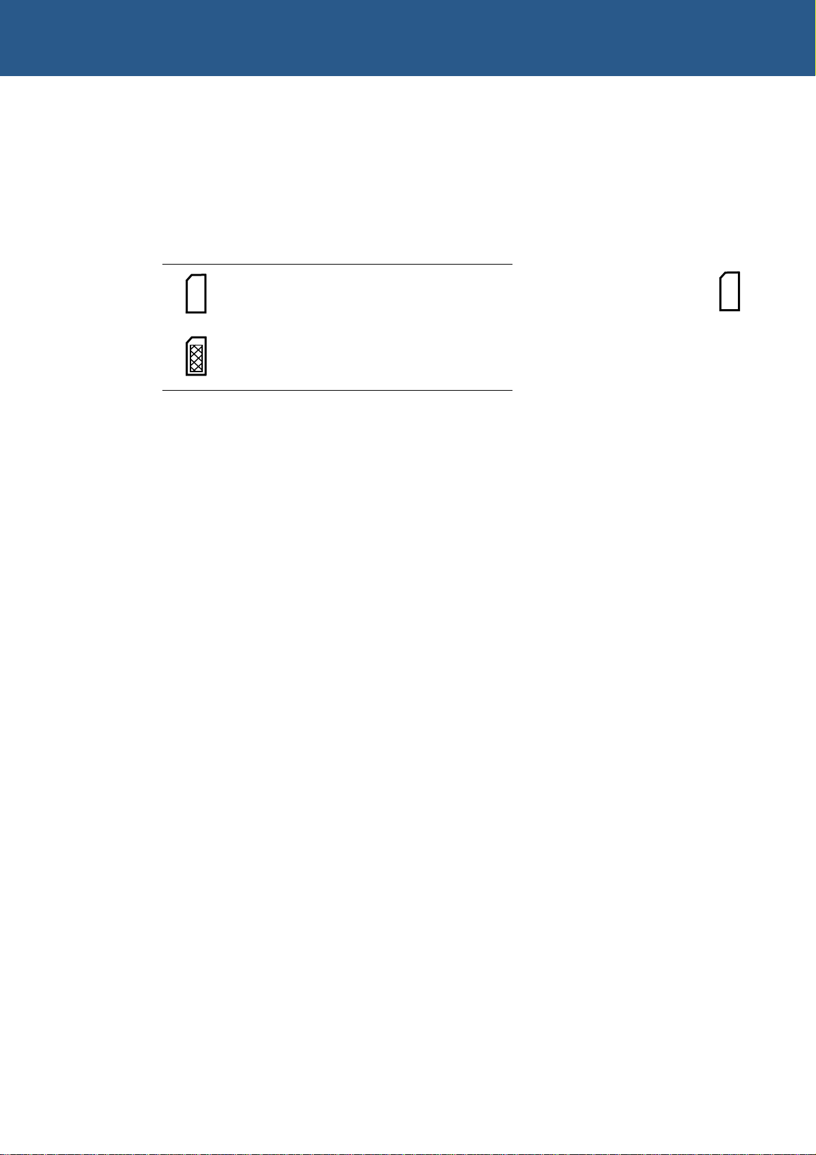
JP4 - Wait state behaviour selection
Computers normally wait for a fixed time for PC104 bus access. If the zero wait state
(0WS) is selected this waiting is skipped and the signal is asserted as soon as the
board decodes a valid address. This can shorten the amount of time spent accessing
the board in some situations.
JP4 Description
Waits for bus access.
Zero wait.
Default setting:

AIM104-COM8 Technical Manual Cable connections
© 2007 Eurotech Ltd Issue C 17
Cable connections
The serial I/O connectors have been wired so that they can be easily split into 9-way
male D-sub connectors with standard pin-outs for PC/AT RS232 serial ports:
The table below shows the corresponding channel and connector pinouts.
40 way IDC ribbon header Male 9 way IDC D-sub Channel Pinout
Pins 1-9 Pins 1-9 0 PC/AT RS232 port
Pins 11-19 Pins 1-9 1 PC/AT RS232 port
Pins 21-29 Pins 1-9 2 PC/AT RS232 port
Pins 31-39 Pins 1-9 3 PC/AT RS232 port
The same cabling applies to both of the 40-way boxed headers.

AIM104-COM8 Technical Manual Appendix A – Contacting Eurotech Ltd
© 2007 Eurotech Ltd Issue C 18
AppendixA– Contacting Eurotech Ltd
Eurotech Ltd sales
Eurotech Ltd’s sales team is always available to assist you in choosing the board that
best meets your requirements.
Eurotech Ltd
3 Clifton Court
Cambridge
CB1 7BN
UK
Tel: +44 (0)1223 403410
Fax: +44 (0)1223 410457
Email: [email protected]
Comprehensive information about our products is also available at our web site:
www.eurotech-ltd.co.uk.
While Eurotech Ltd’s sales team can assist you in making your decision, the
final choice of boards or systems is solely and wholly the responsibility of the
buyer. Eurotech Ltd’s entire liability in respect of the boards or systems is as set
out in Eurotech Ltd’s standard terms and conditions of sale. If you intend to
write your own low level software, you can start with the source code on the
disk supplied. This is example code only to illustrate use on Eurotech Ltd’s
products. It has not been commercially tested. No warranty is made in respect
of this code and Eurotech Ltd shall incur no liability whatsoever or howsoever
arising from any use made of the code.
Eurotech Ltd technical support
Eurotech Ltd has a team of dedicated technical support engineers available to provide
a quick response to your technical queries.
Tel: +44 (0)1223 412428
Fax: +44 (0)1223 410457
Email: [email protected]
Eurotech Ltd Group
Eurotech Ltd is a subsidiary of Eurotech Group. For further details see
www.eurotech.com

AIM104-COM8 Technical Manual Appendix B – Connector details
© 2007 Eurotech Ltd Issue C 19
Appendix B – Connector details
The serial port connections are routed to two 40-way headers on the AIM104-COM8.
One of these connectors, J3, has the channel 0 – 3 signals and the other, J1, has the
channel 4 – 7 signals. The pinout details for these connectors are shown below:
J3 channel 0 – 3
Connector: 40 way, 2.54mm (0.1”) x 2.54mm (0.1”) dual row right angle boxed header.
Mating Connector: Framatome 71600-040
Pin Signal Name Pin Signal Name
1 DCD0 2 DSR0
3 RXD0 4 RTS0
5 TXD0 6 CTS0
7 DTR0 8 RI0
9 GND 10 GND
11 DCD1 12 DSR1
13 RXD1 14 RTS1
15 TXD1 16 CTS1
17 DTR1 18 RI1
19 GND 20 GND
21 DCD2 22 DSR2
23 RXD2 24 RTS2
25 TXD2 26 CTS2
27 DTR2 28 RI2
29 GND 30 GND
31 DCD3 32 DSR3
33 RXD3 34 RTS3
35 TXD3 36 CTS3
37 DTR3 38 RI3
39 GND 40 GND
39
1
40
2

AIM104-COM8 Technical Manual Appendix B – Connector details
© 2007 Eurotech Ltd Issue C 20
J1 channel 4 - 7
Connector: 40 way, 2.54mm (0.1”) x 2.54mm (0.1”) dual row right angle boxed header
Mating Connector: Framatome 71600-040
Pin Signal Name Pin Signal Name
1 DCD4 2 DSR4
3 RXD4 4 RTS4
5 TXD4 6 CTS4
7 DTR4 8 RI4
9 GND 10 GND
11 DCD5 12 DSR5
13 RXD5 14 RTS5
15 TXD5 16 CTS5
17 DTR5 18 RI5
19 GND 20 GND
21 DCD6 22 DSR6
23 RXD6 24 RTS6
25 TXD6 26 CTS6
27 DTR6 28 RI6
29 GND 30 GND
31 DCD7 32 DSR7
33 RXD7 34 RTS7
35 TXD7 36 CTS7
37 DTR7 38 RI7
39 GND 40 GND
40
1
39
2
Table of contents
Other Eurotech Motherboard manuals

Eurotech
Eurotech PROTEUS User manual

Eurotech
Eurotech BitsyXb User manual

Eurotech
Eurotech Titan User manual

Eurotech
Eurotech Bitsy G5 User manual

Eurotech
Eurotech ISIS-1.6-M1G-F2G-GPS User manual

Eurotech
Eurotech ALUDRA User manual

Eurotech
Eurotech Titan User manual

Eurotech
Eurotech ZEUS User manual

Eurotech
Eurotech Apollo User manual

Eurotech
Eurotech Vector User manual


