Eurotech GEMINI User manual
Rev. 4.0 - April 2009 - ETH_GEMINI_USM
DIGITAL TECHNOLOGIES FOR A BETTER WORLD
www.eurotech.com
USER MANUAL
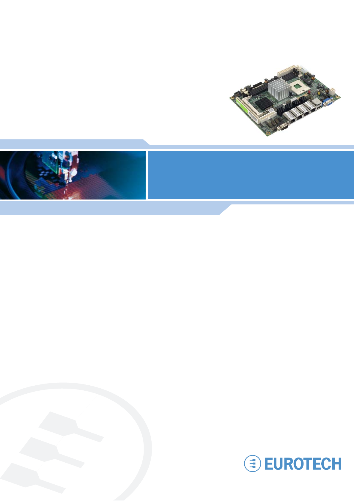
GEMINI
5¼" embedded miniboard

DISCLAIMER
The information in this document is subject to change without notice and should not be construed as a commitment
by any Eurotech company. While reasonable precautions have been taken, Eurotech assumes no responsibility for
any error that may appear in this document.
WARRANTY
This product is supplied with a 3 year limited warranty. The product warranty covers failure of any Eurotech
manufactured product caused by manufacturing defects. The warranty on all third party manufactured products
utilised by Eurotech is limited to 1 year. Eurotech will make all reasonable effort to repair the product or replace it
with an identical variant. Eurotech reserves the right to replace the returned product with an alternative variant or
an equivalent fit, form and functional product. Delivery charges will apply to all returned products. Please check
www.eurotech.com for information about Product Return Forms.
TRADEMARKS
PhoenixTM and PhoenixBIOSTM are trademarks of Phoenix Technologies Limited.
Linux is a registered trademark of Linus Torvalds.
RedBoot, Fedora and Red Hat are registered trademarks of Red Hat Inc. This product contains a copy of the
installation media for the Fedora Linux distribution. This media is not a product of Red Hat, Inc. or the Fedora
project and is not endorsed by Red Hat, Inc. or the Fedora project. It is a product of Eurotech and we have no
relationship with Red Hat, Inc. or the Fedora project. The media is identical in every respect to the standard Fedora
install media.
Intel®, Pentium®and Celeron®are registered trademarks of the Intel Corporation.
CompactFlash is the registered trademark of SanDisk Corp.
All other trademarks and copyrights referred to are the property of their respective owners.
REVISION HISTORY
Issue no. PCB Date Comments
A 21st July 2007 First full release of the manual.
B 1st October 2007 Minor updates, Eurotech rebranding.
C 12th May 2008 Minor updates.
D 2nd April 2009 Minor updates and new branding.
© 2009 Eurotech. All rights reserved.
For contact details, see page 55.

Contents
Issue D 3
Contents
Introduction...............................................................................................................................4
GEMINI ‘at a glance’.....................................................................................................5
Features .......................................................................................................................6
Support products ..........................................................................................................8
Development kits ..........................................................................................................8
Product handling and environmental compliance.........................................................9
Conventions................................................................................................................10
Getting started with your GEMINI........................................................................................... 11
What’s in the box? ...................................................................................................... 11
CPU configuration ......................................................................................................12
Installing the processor and the memory....................................................................13
Connecting a floppy disk drive....................................................................................14
Connecting a hard disk drive ......................................................................................14
Connecting a CD-ROM (IDE Type).............................................................................14
Connecting a CompactFlash®card.............................................................................15
Connecting a keyboard...............................................................................................15
Connecting a mouse...................................................................................................15
Using the serial interfaces (RS232/422/485)..............................................................15
Connecting a printer ...................................................................................................16
Using the audio features.............................................................................................16
Using the flat panel interface ......................................................................................16
Using the USB ports ...................................................................................................17
Using the Ethernet interface .......................................................................................17
Connecting a monitor .................................................................................................17
Connecting a television ..............................................................................................17
Setting up the BIOS....................................................................................................17
Jumpers and connectors ........................................................................................................18
Jumpers......................................................................................................................20
Connectors .................................................................................................................23
Detailed hardware description ................................................................................................40
GEMINI block diagram ...............................................................................................40
Processor ...................................................................................................................41
GEMINI chipset ..........................................................................................................42
Graphics and Memory Controller Hub ........................................................................42
Display interfaces .......................................................................................................43
Enhanced IDE and CompactFlash interface...............................................................43
Serial ATA interface.....................................................................................................43
LAN interface..............................................................................................................44
Serial ports .................................................................................................................44
Super IO .....................................................................................................................44
System control interface .............................................................................................46
Onboard audio interface .............................................................................................46
USB 2.0 interface .......................................................................................................46
Power and fan connector............................................................................................46
Appendix A – Product specification.........................................................................................47
Appendix B – Mechanical drawing .........................................................................................49
Appendix C – System resources ............................................................................................50
Appendix D – RoHS-6 Compliance - Materials Declaration Form ..........................................53
Eurotech Group Worldwide Presence ....................................................................................55

GEMINI user manual
Issue D
4
Introduction
The GEMINI is an EBX format, high-performance, high-functionality PC-compatible
processor board designed for embedding into OEM equipment. The board is based on
the Intel®945GME/ICH7-M chipset and supports a range of Intel Core 2 Duo / Core Duo /
Core Solo / Celeron M 4xx (Merom/Yonah) processors to offer a combination of high
performance computing features with low power dissipation.
GEMINI is a 5¼" embedded miniboard that provides:
•Intel Yonah dual core processor support.
The board supports Intel Core Duo/Core Solo processors with 533/667MHz front side
bus, 2MB L2 cache, to provide powerful performance.
•Intel 945GME and ICH7-M chipset.
Based on the Intel 945GME and ICH7-M chipset, the board provides a new
generation mobile solution offering:
- Intel GMA950 graphics.
- DDR2 533/667 memory.
- Built-in high speed serial ATA interface.
- AC97 Audio with 5.1 surround sound.
•All-in-one multimedia solution.
The board provides high performance onboard graphics, 24-bit Dual channel LVDS
interface, CRT, DVI and HDTV, to meet requirements of demanding multimedia
applications.
•Flexible Extension Interface.
A CompactFlash Type II socket and mini-PCI socket are available.
It also offers all standard features and connectors found on a PC motherboard including:
•PCI slot
•Floppy drive interface.
•Four Ethernet ports.
•Four serial ports, parallel port, IrDA port, PS/2 port.
•Secondary IDE interface.
•Six USB 2.0 compliant ports.
•General purpose IO.
Introduction
Issue D 5
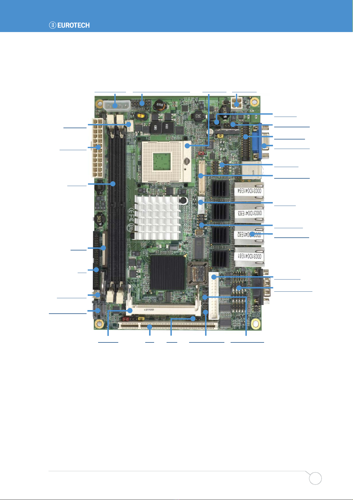
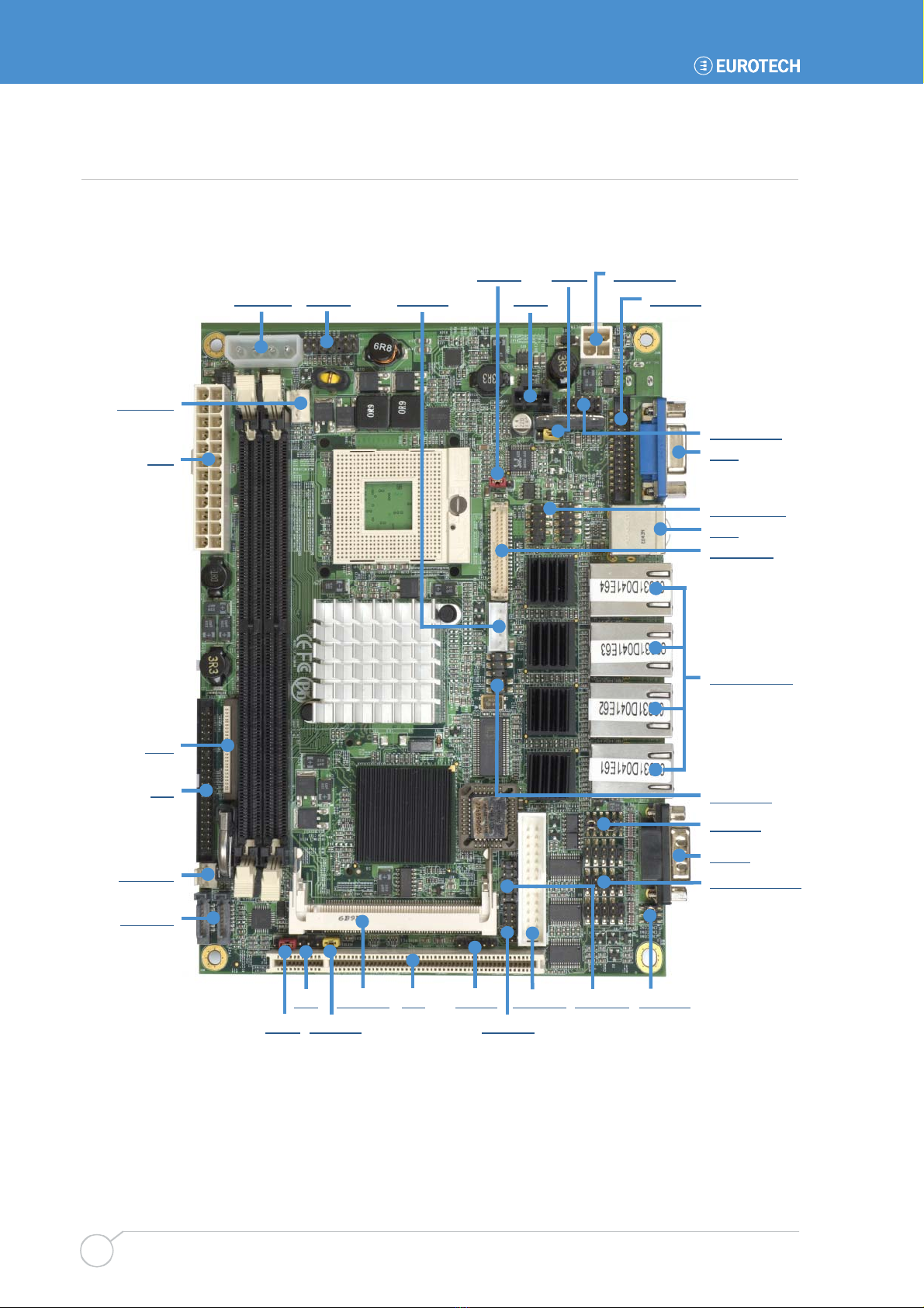
GEMINI ‘at a glance’
Power output System control interface Processor DC supply
Mini PCI PCI IrDA GPIO interface PS/2 interface
CD Audio
A
udio interface
DVI interface
A
nalogue RGB
USB ports
LVDS interface
Backlight
TV interface
LAN interfaces
Printer port
Serial interfaces
CPU FAN
ATX supply
Memory
Floppy
IDE
System FAN
SATA interfaces

GEMINI user manual
Issue D
6
Features
The features included in the GEMINI are described below:
Processor
•Intel Core 2 Duo / Core Duo / Core Solo / Celeron M 4xx Processor (Merom/Yonah)
at 533 / 667MHz FSB.
Chipset
•Intel 945GME Northbridge and ICH7-M Southbridge.
BIOS
•Phoenix-Award v6.00PG 4Mb PnP flash BIOS.
System memory
•Two DDR2 533/667MHz SDRAM up to 3GB (Non-ECC, unbuffered memory is
supported only).
Video
•Intel 945GME GMCH (Graphic Memory Controller Hub) integrated GMA (Graphic
Media Accelerator) 950 Technology.
•Up to 224MB shared with system memory.
•VGA, DVI, LVDS and SD/HDTV outputs.
Integrated I/O
•Winbond W83627THG LPC Super I/O.
Audio
•Intel ICH7-M integrated with Realtek ALC655 5.1 Ch AC97 Codec.
Enhanced IDE
•Onboard 44-pin IDE (supports DOM).
Floppy port
•Supports two floppy drives 360kB, 720kB, 1.2MB, 2.88MB.
Parallel port
•Standard, Enhanced and Extended Parallel Port mode supported (SPP/EPP/ECP).
Serial ports
•Three RS-232 and one RS-232/422/485/IrDA serial ports.

Introduction
Issue D 7
USB interface
•Two external and four internal Hi-Speed USB 2.0 ports with 480Mbps of transfer rate.
Network support
•Four Intel 82573L Gigabit Ethernet controllers.
•Triple speed 10/100/1000Base-T, auto-switching Fast Ethernet, Full duplex,
IEEE802.3U compliant.
Expansion
•One 8-bit programmable I/O interface (x8 Global Purpose Digital I/O's).
•One PCI slot supports up to two PCI devices through riser card.
•One Mini PCI socket.
•One CompactFlash socket
Size
•EBX compatible footprint 5.75" x 8.00" (146mm x 203mm).

GEMINI user manual
Issue D
8
Support products
The GEMINI is supported by the following optional product:
•1U 19" wide GEMINI ICE (Industrial Compact Enclosure)
Provides easy-to-use system solutions for embedded SBC applications. It is manufactured
from 0.9mm (20 SWG) finished mild steel. The enclosure conforms to the 19" 1EC6O297-
1/2 DIN 41494 and MEP IEC 60917-2-1 standards and therefore meets the 19" 1U
specification in height and width. Depth is approximately 13.8 inches (350mm).
The GEMINI ICE contains:
- 180W AC ATX PSU: Auto-ranging 100-240V AC at 47 - 63Hz.
- DC input PSU option available, please contact Eurotech sales.
- Standard I/O connections from rear panel.
- On/Off and reset switch and power and HDD activity LEDs on a front panel.
- Front panel connections for four USB ports.
- PCI riser card with two card expansion slots.
- Hard disk drive and CD/DVD reader/writer.
- Two system fans.
- Front panel LCD display with navigation keys and user LEDs.
•LCD display
An AU Optronics 15" XGA (1024x768) colour TFT LCD display interfaces directly with
the LVDS signals provided by the GEMINI. The display has a 400:1 contrast ratio,
16ms response time and a dual CCFL backlight providing 350nits of screen brightness.
•TSC1 (TouchScreen Controller)
The Eurotech TSC1 can be used to provide analogue resistive touchscreen support
for the GEMINI. The TSC1 is designed to directly interface between four-, five- or
eight-wire analogue touchscreens and a serial connection. A custom cable can be
used to connect directly to one of the RS232 ports on the GEMINI. A separate +5V
connection is also required.
•15" Touchscreen
Glass-backed 15" touchscreens are available for use in conjunction with the 15" LCD
display. Two touchscreens are available: a four-wire option and an eight-wire option.
These interface directly with the Eurotech TSC1 touchscreen controller.
For more details about any optional products, please go to www.eurotech.com or contact
the Eurotech sales team (see page 55).
Development kits
Eurotech offers a development kit for the GEMINI board. Two configurations are available:
•Windows XP Embedded contained on 2GB USB Flash®disk module.
•Embedded Linux contained on 2GB USB Flash®disk module.
With this configuration the GEMINI board is supplied with an Intel Core 2 Duo T7400 2.16
GHz processor and a 1GB PC5300 DDR2 SDRAM DIMM.
For more details about any of the above options, please go to www.eurotech.com or
contact the Eurotech sales team (see page 55).

Introduction
Issue D 9
Product handling and environmental compliance
Anti-static handling
This board contains CMOS devices that could be damaged in the event of static
electricity being discharged through them. At all times, please observe anti-static
precautions when handling the board. This includes storing the board in appropriate anti-
static packaging and wearing a wrist strap when handling the board.
Battery
The board contains a Lithium non-rechargeable battery. Do not short-circuit the battery or
place on a metal surface where the battery terminals could be shorted.
When disposing of the board or battery, take appropriate care. Do not incinerate, crush or
otherwise damage the battery.
Packaging
Please ensure that should a board need to be returned to Eurotech it is adequately
packed, preferably in the original packing material.
Electromagnetic compatibility (EMC)
The GEMINI is classified as a component with regard to the European Community EMC
regulations and it is the user’s responsibility to ensure that systems using the board
comply with the appropriate EMC standards.
RoHS Compliance
The European RoHS Directive (Restriction on the use of certain Hazardous Substances –
Directive 2002/95/EC) limits the amount of 6 specific substances within the composition
of the product. The GEMINI and associated accessory products are available as RoHS-6
compliant options only. A full RoHS Compliance Materials Declaration Form is included in
this manual - see Appendix D – RoHS-6 Compliance - Materials Declaration Form on
page 53. Further information about RoHS compliance is available on the Eurotech web
site at www.eurotech.com/RoHS_and_WEEE.

GEMINI user manual
Issue D
10
Conventions
The following symbols are used in this guide:
Symbol Explanation
Note - information that requires your attention.
Tip - a handy hint that may provide a useful alternative or save time.
Caution – proceeding with a course of action may damage your equipment
or result in loss of data.
Jumper is fitted.
Jumper is not fitted.
3
2
1
Jumper fitted on pins 1-2.
3
2
1
Jumper fitted on pins 2-3.

Getting started with your GEMINI
Issue D 11
Getting started with your GEMINI
Once you have a working GEMINI system, you can start adding other peripherals to
enable you to start development. In this section we guide you through setting up and
using peripherals and some of the features of the GEMINI.
The GEMINI uses a Phoenix-Award BIOS (Basic Input-Output System) to provide
support for the board as standard. BIOS defaults have been selected to enable the board
to operate with a minimum of devices connected. If you want to change these default
settings, you use the Phoenix-Award BIOS setup program.
The setup parameters are stored in the CMOS RAM and are retained when the power is
switched off, providing the battery backup supply is connected. If no battery is installed or
the CMOS settings are corrupted then the BIOS will restore them from an onboard
CMOS EEPROM.
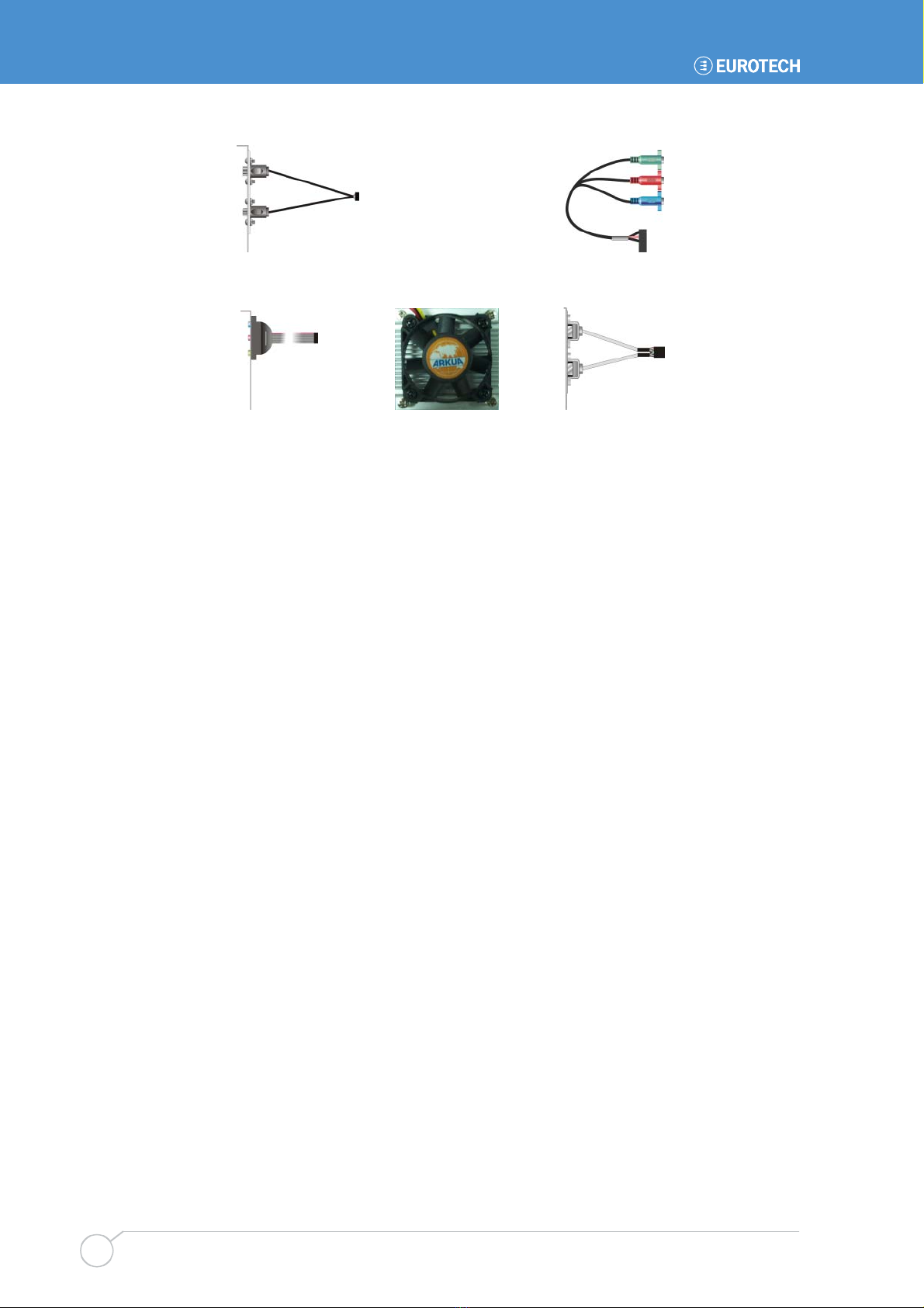
What’s in the box?
The GEMINI product includes one GEMINI motherboard and a cable kit. The cable kit
includes the following items:
ATA33 IDE cable x 1 PS/2 cable x 1
SATA cable x 2 Power cable x 1
26-pin slim type floppy cable x 1 COM and printer port cable x 1
COM port cable x 1 DVI/SDTV module with bracket x 1
GEMINI user manual
Issue D
12
SDTV cable x 1 YPbPr cable x 1
Audio port cable x 1 CPU cooler x 1 USB cable x 1
CPU configuration
The GEMINI board has been specifically designed to support a range of Intel processors.
The appropriate voltage and speed selections are configured during the boot process. No
user configuration is required.
Getting started with your GEMINI
Issue D 13
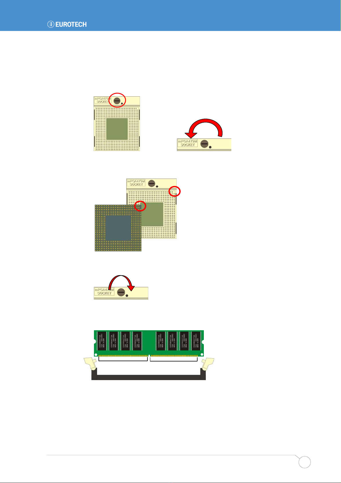
Installing the processor and the memory
To install the CPU, follow these steps:
1Use the flat-type screw drive to unlock the CPU socket.
2Follow the pin direction to install the processor on the socket.
3Lock the socket.
When installing the memory module, check that the pin number matches the slot side:
112-pin128-pin
Unlock

GEMINI user manual
Issue D
14
Connecting a floppy disk drive
To connect a floppy device to the board, follow these steps:
1Lift up the plastic bar on the rear of the floppy device.
2Slot in the 26-pin ribbon cable provided (blue paste for outside).
3Press back the plastic bar.
4On the GEMINI board, lift up the brown plastic bar.
5Slot in the cable (blue paste for brown bar side). (See Jumpers and
connectors on page 18 for the location of the floppy port.)
6Press back the plastic bar.
Connecting a hard disk drive
The GEMINI provides an Integrated Serial ATA Host Controller, enabling up to two SATA
devices to be connected. There is also a single secondary IDE controller, enabling up to
two IDE devices to be connected. Down to one only if the CF socket is in use.
When connecting SATA peripherals to the GEMINI, the BIOS automatically sets the
following configuration:
Primary Master: Device connected to the onboard connector SATA1.
Primary Slave: Device connected to the onboard connector SATA2.
Secondary Master: Device connected the IDE port and set-up as a MASTER.
Secondary Slave: Device connected the IDE port and set-up as a SLAVE.
The BIOS automatically detects the hard disk drive(s) during the POST processes and
configures the hardware correctly. The BIOS allows either a master or slave device to be
the boot device.
Connecting a CD-ROM (IDE Type)
If a CD-ROM drive is required in the system, it may be connected in place of a secondary
drive (as detailed above). The CD-ROM should be configured as a ‘master’ device.
Drivers are required to support a CD-ROM drive under DOS. If a bootable CD is inserted
in the drive, the BIOS can be configured to automatically boot from this CD.

Getting started with your GEMINI
Issue D 15
Connecting a CompactFlash®card
The GEMINI has a single CF+ version 2.0 Type II CompactFlash®socket that supports
both Type I and Type II CompactFlash cards.
The CompactFlash socket is interfaced to the IDE controller. If a CompactFlash card is
plugged into the socket it acts as a normal hard disk drive and is detected by the BIOS
during the POST process. If the card has an operating system loaded and is correctly
configured to be bootable, it can be selected as a boot device from the BIOS boot menu.
The CompactFlash card can only be inserted into the socket one way. The correct
orientation is for the top of the card (i.e. the normal printed side) to be faced down to the
PCB.
For further details about the CompactFlash socket, see Enhanced IDE and
CompactFlash interface on page 43.
Connecting a keyboard
A PS/2 keyboard can be connected to the PS/2 MiniDIN Connector via the PS/2 cable
supplied. A USB keyboard can also be connected to any USB port available. See
CN_PS2: PS/2 connector on page 36 for more information.
Connecting a mouse
A PS/2 mouse can be connected to the PS/2 MiniDIN Connector via the PS/2 cable
supplied. A USB mouse can also be connected to any USB port available. See CN_PS2:
PS/2 connector on page 36 for more information.
Using the serial interfaces (RS232/422/485)
The four serial port interfaces on the GEMINI are fully PC compatible. COM1 to COM4
are decoded at standard PC address locations. PC applications can use these ports
without any special configuration.
The BIOS setup screens are used to configure the operation of each of the serial ports.
Connection to COM1 is via a standard DB9-M connector mounted on the PCB. COM2 to
COM4 are interfaced via a 10-way boxed header. The pin assignment of these headers
matches the standard 9-way D-Type plug one (pin to pin connection). A suitable cable is
provided in the box. The D-type connector is compatible with the standard 9-way
connector on a desktop machine.
See JSEL1/2: COM2 RS232/422/485 mode setting on page 22 for further details about
the serial port interface, and page 28 for pin details.

GEMINI user manual
Issue D
16
Connecting a printer
An enhanced printer port is incorporated into the GEMINI. This port can be used to
support a Centronics-compatible printer or ECP/EPP bi-directional device. The port
signals are available on a 26 way boxed header and the pin assignment has been
arranged to allow 1:1 connection with a 25-way IDC D-Type socket. A suitable cable is
provided in the box. The D-type socket is compatible with a standard printer port
connector on a desktop machine.
See page 36 for pin details.
Using the audio features
The GEMINI provides an AC97 audio codec that supports standard line in, line out,
microphone functionality, or alternatively can be configured in software to support the 5.1
speaker output format. The audio input/outputs are available through a 10 pin header. An
onboard CD audio input connector is also available.
See Audio connector on page 26 for further details.
Using the flat panel interface
The GEMINI provides a dual channel LVDS LCD display header that can be used to
directly interface to LVDS LCD displays up to a maximum resolution of 1600x1200. The
display type is selected from the BIOS video setup menu:
The panel type mapping options are listed below:
18 bits Single channel 24 bits Single channel 24 bits Dual channel
No. Output format No. Output format No. Output format
1 640 x 480 4 1280 x 768 9 1024 x 768
2 800 x 600 5 1280 x 1024 10 1280 x 768
3 1024 x 768 6 1366 x 768 11 1280 x 1024
7 1280 x 800 12 1366 x 768
8 1600 x 1200 13 1400 x 1050
14 1024 x 768 15 1600 x 1200

Getting started with your GEMINI
Issue D 17
Using the USB ports
USB ports 1 and 2 are standard USB Type A connectors. USB Ports 3&4 and USB ports
5&6 are provided on a 10-way header (CN_USB1/2) designed to be compatible with PC
expansion brackets that support two USB sockets.
See pages 27, 38 and 46 for further details.
Using the Ethernet interface
The GEMINI provides four 10/100/1000 Ethernet ports as standard, thus providing
Gigabit Ethernet capability.
Ethernet interfaces are capable of supporting network boot features. Four rear panel RJ-
45 pin connectors provide the Ethernet interface. To support Gigabit Ethernet capabilities,
a cable rated to CAT5e or above with four signals pairs should be used.
Further information on the Ethernet interfaces is available on page 44.
Connecting a monitor
Connect the CRT or analogue LCD monitor with DB15 male plug to the onboard DB15
female connector on rear I/O port. You can also use a DVI monitor connected to the DVI-I
connector available on the DVI/SDTV breakout board provided in the kit.
Connecting a television
The GEMINI supports both SDTV and HDTV. You can either use the S-Video or
composite cable supplied to connect to a standard television or use the YPrPb
component cable to connect to a High Definition TV for better resolution performance.
The DVI/SDTV breakout board also provides S-Video and composite interfaces.
Setting up the BIOS
The motherboard uses the Award BIOS for the system configuration. The Award BIOS in
the single board computer is a customized version of the industrial standard BIOS for
IBM PC AT-compatible computers. It supports Intel x86 and compatible CPU architecture
based processors and computers. The BIOS provides critical low-level support for the
system central processing, memory and I/O sub-systems.
The BIOS setup program of the single board computer lets the customers modify the
basic configuration setting. The settings are stored in a dedicated battery-backed
memory, NVRAM, retaining the information when power is turned off. If the battery runs
out of the power, the BIOS settings will be set to the default programmed values.
To activate the CMOS Setup program, press DEL immediately after you turn on the
system. The following message ‘Press DEL to enter SETUP’ should appear in the lower
left hand corner of your screen. When you enter the CMOS Setup Utility, the Main Menu
is displayed. You can use arrow keys to select the required menu, press Enter to accept
the selection and enter the sub-menu.
GEMINI user manual
Issue D
18
Jumpers and connectors
The following diagram shows the jumpers and connectors on the top side of the GEMINI.
Click on the name of any jumper or connector for details:
JVLCD JCRT CN_DCIN
DC_OUT JFRNT CN_INV CDIN CN_DVI
JAT MINIPCI PCI CN_IR CN_LPT CN_PS2 JCSEL1
JRTC JCFSEL CN_DIO
CN_AUDIO
CRT
CN_USB1/2
USB
CN_LVDS
RJ45_1/2/3/4
CN HDTV
JCSEL2
COM1
CN_COM2/3/4
CPUFAN
ATX
FDD
IDE
SYSFAN
SATA1/2

GEMINI user manual
Issue D
20
Jumpers
Jumper Function Further information …
JRTC CMOS operating/clear setting See below.
JCFSEL CompactFlash mode setting See below.
JVLCD LCD panel voltage setting See the next page.
JCRT CRT attach select setting See the next page.
JAT Power mode select See the next page.
JCSEL1/2 COM2 RS232/422/485 mode setting See page 22.
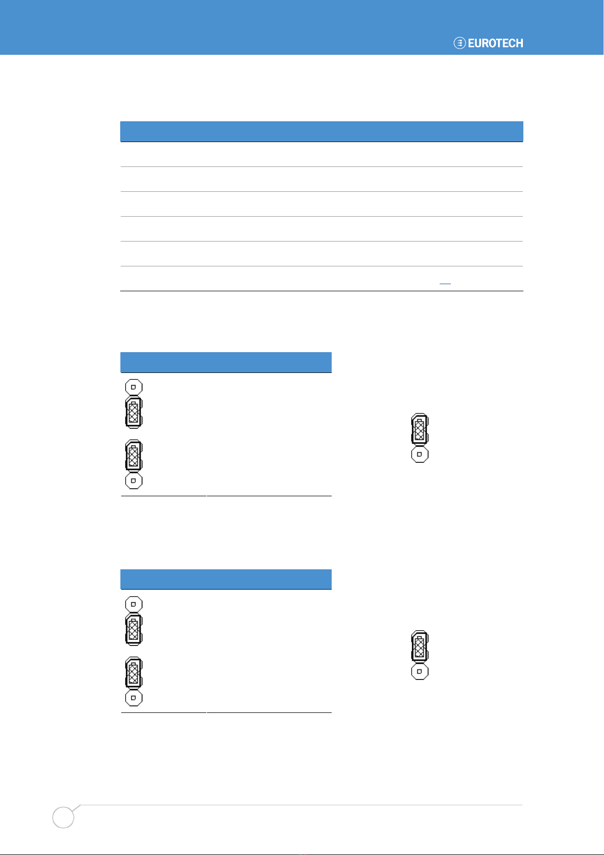
JRTC: CMOS operating/clear setting
Used to clear the contents of the CMOS RAM.
JRTC Explanation
3
2
1
Clear CMOS
3
2
1
Normal operation
Default setting:
3
2
1
JCFSEL: CompactFlash mode setting
Used to specify whether the CompactFlash Type II socket is operating in Slave or Master
mode on the secondary IDE channel.
JCFSEL Explanation
3
2
1
Master
3
2
1
Slave
Default setting:
3
2
1
Table of contents
Other Eurotech Motherboard manuals

Eurotech
Eurotech Bitsy G5 User manual

Eurotech
Eurotech Vector User manual

Eurotech
Eurotech Apollo User manual

Eurotech
Eurotech ZEUS User manual

Eurotech
Eurotech VIPER User manual

Eurotech
Eurotech ALUDRA User manual

Eurotech
Eurotech BitsyXb User manual

Eurotech
Eurotech Titan User manual

Eurotech
Eurotech AIM104-COM8 User manual

Eurotech
Eurotech PROTEUS User manual


