Eurotech PXA320 User manual
Rev. A - July 2009
DIGITAL TECHNOLOGIES FOR A BETTER WORLD
www.eurotech.com
USER MANUAL
Graphics ClientM
PXA320 Single Board Computer

Disclaimer
The information in this document is subject to change without notice and should not be construed as a commitment
by any Eurotech company. While reasonable precautions have been taken, Eurotech assumes no responsibility for
any error that may appear in this document.
Trademarks
All product or service names are the property of their respective owners.
Revision History
Issue no.
PWB
Date
Comments
1 Jul-2008 Preliminary release
2
Feb-2009
Second preliminary release
Style and formatting updates
Hardware and System Specifications added
Revision 4 updates
A
Jul-2009
Initial release
Rev A updates
© 2008 Eurotech Inc.
For contact details, see page 61.

Contents
110120-1000A 3
Contents
Introduction............................................................................................................................ 5
Block Diagram ........................................................................................................... 5
Features .................................................................................................................... 6
Handling Your Board Safely ....................................................................................... 8
Conventions............................................................................................................... 9
Software Specification.......................................................................................................... 10
Hardware Specification .........................................................................................................11
Core Processor.........................................................................................................11
Memory.................................................................................................................... 12
Synchronous DRAM..................................................................................... 12
Non-volatile Memory .................................................................................... 13
Flash Memory .................................................................................. 13
Real-Time Clock............................................................................... 13
External Memory.......................................................................................... 13
CompactFlash Card ......................................................................... 13
SD/MMC Card.................................................................................. 13
USB Disk Drive ................................................................................ 13
Communications ...................................................................................................... 14
USB Ports .................................................................................................... 14
Serial Ports .................................................................................................. 16
Ethernet ....................................................................................................... 17
SD/MMC Interface........................................................................................ 17
CAN 2.0B Bus.............................................................................................. 18
1-Wire Bus ................................................................................................... 18
I2C Bus......................................................................................................... 18
User Interface and Display....................................................................................... 19
Display ......................................................................................................... 19
VEE Adapter ................................................................................................ 19
Backlight ...................................................................................................... 20
Touch Panel ................................................................................................. 20
Audio Interface............................................................................................. 20
Camera Sensor Interface (optional) ......................................................................... 21
Inputs and Outputs................................................................................................... 22
General-Purpose Inputs and Outputs ........................................................... 22
ADSmartIO................................................................................................... 22
Digital I/O ......................................................................................... 23
A/D Inputs ........................................................................................ 23
Keypad Scan.................................................................................... 23
Power and Power Management ............................................................................... 24
Mechanical............................................................................................................... 26
Connectors, LEDs, and Jumpers ......................................................................................... 29
Identifying Connectors ............................................................................................. 29
Switches, Controls, and Indicators ........................................................................... 29

Graphics ClientM User Manual
110120-1000A
4
SW1: Reset................................................................................................. 29
LED Indicators.............................................................................................. 30
Signal Headers ........................................................................................................ 30
J1: Power Input ........................................................................................... 30
J2: CompactFlash ....................................................................................... 31
J3: Ethernet................................................................................................. 31
J4: USB Host 1 and USB Host 2 (optional).................................................. 31
J5: Touch Panel........................................................................................... 32
J6: LCD....................................................................................................... 32
J7: VEE Adapter.......................................................................................... 33
J8: Backlight................................................................................................ 34
J9: SD/MMC 2............................................................................................. 34
J10: SD/MMC 1........................................................................................... 35
J11: ADSmartIO and 1-Wire ........................................................................ 35
J12: USB 1.1 Client or USB 2.0 Client (optional) ......................................... 37
J13: Wakeup ............................................................................................... 37
J14: Serial 3 (EIA-232) ................................................................................ 38
J15: Serial 1 (EIA-232) ................................................................................ 38
J16: Serial 2 (EIA-232) ................................................................................ 39
J17: Stereo Speaker: Left Channel.............................................................. 39
J18: Headphone Out and Audio Line In....................................................... 40
J19: Stereo Speaker: Right Channel............................................................ 40
J21: GPIO, I2C, and CSI (optional) ............................................................. 41
J22: GPIO, Serial 1 (EIA-422/485), and Reset ............................................ 43
J23: CAN 2.0B Bus ..................................................................................... 44
J99: In-System Programming ...................................................................... 45
J100: Audio Line In (Mono).......................................................................... 45
System Specification............................................................................................................ 46
Power Supply........................................................................................................... 46
Power Supply............................................................................................... 46
Power Consumption..................................................................................... 46
Electrical .................................................................................................................. 47
PXA320 Processor....................................................................................... 47
CPLD ........................................................................................................... 48
Reset and Wake Up Inputs........................................................................... 49
Display, VEE Adapter, and Backlight ............................................................ 49
ADSmartIO................................................................................................... 51
Audio Interface............................................................................................. 52
General.................................................................................................................... 53
Crystal Frequencies ..................................................................................... 53
Real-Time Clock........................................................................................... 53
Environmental .......................................................................................................... 53
Appendix A – Reference Information.................................................................................... 54
Appendix B – RoHS Compliance ......................................................................................... 56
Appendix C – Board Revision .............................................................................................. 57
Appendix D – Development Kit ............................................................................................ 59

Introduction
110120-1000A 5
Introduction
The Graphics ClientM (GCM) is a low-power single-board computer based on the
Marvell® PXA320 processor. The PXA320 processor integrates scalable general-
purpose processing, 2D graphics acceleration, and wireless technology to provide
hardware-accelerated graphics display and high-powered computing capabilities. The
GCM is ideal for running graphics-intensive applications, especially those requiring
wireless connectivity, and is targeted towards hand-held, medical, fleet management, and
embedded markets.
In addition to industry-standard interfaces, the GCM includes the ADSmartIO™. The
ADSmartIO extends GCM capabilities by providing a wide array of customizable
functions and I/O.
This manual provides details about the various features of the GCM and about how they
create a system that meets your application needs. It is intended for embedded system
integrators and software application developers. Design details apply to the revision listed
in Appendix C – Board Revision, page 57.
Block Diagram
The following diagram illustrates the system organization of the GCM. The functionalities
shown with dotted lines or labelled as optional are available as volume production
options. The following sections provide further details about these various options.
For detailed mechanical drawings of the GCM, see Mechanical, page 26.
Power
Supply
ADSmartIO
1-WIRE
I2C
Touch panel
CPLDIOs
PXA320
Processor
DDR
SDRAM
Audio Line In
Headphone Out
Stereo Speaker
3 x UART
LCD
Backlight
VEE Adapter
LCD I/F
Touch Panel
Ctrl
GPIOs
Digital I/O
Up to 8 x A/D Inputs
Up to 8 x 8 Keypad
Touch panel
USB 1.1 Host
BAT
I2C_P Flash
Memory
2 x SD/MMC
UTMI
I2C
CSI
AC ’97
Audio
Codec
CPLD
Compact Flash
CAN 2.0B Bus
Ethernet
Ethernet
Ctrl
CAN Ctrl
MUX
SPI
RTC
Graphics ClientM
2 x USB
2 x SD/MMC
I2C Bus
5 x GPIO
USB 1.1 Client or
Optional USB 1.1 Host
Optional CSI or
Optional USB 2.0 Client
3 x EIA-232
Up to 22 x GPIO
1-Wire
Wakeup
DC Power Input

Graphics ClientM User Manual
110120-1000A
6
Features
Processor
•Marvell® PXA320 processor
•32 kB instruction and 32 kB data L1 cache, 256 kB L2 cache
•Hardware 2D graphics accelerator
•Intel® Wireless MMX™ 2 technology
•Clock rates up to 624 MHz
Memory
•128 MB DDR SDRAM with support for up to 256 MB
•128 MB NAND Flash memory with support for up to 1 GB
•Battery-backed real-time clock
•External memory support
- CompactFlash, Type I and II, 3.3 V
- USB disk drive
- SD/MMC card
Communications
•USB support
- One USB 1.1 host port and one USB 1.1 client port
- Optional second USB 1.1 host port and optional USB 2.0 client port
(For further details, see USB Ports, page 14.)
•Three serial ports
- Serial 1: 9-wire, EIA-232 or optional EIA-422/485
- Serial 2: 5-wire, EIA-232 or optional 3.3 V with IrDA support
- Serial 3: 5-wire, EIA-232 or optional 3.3 V with Bluetooth support
•10/100 BT Ethernet interface
•Two SD/MMC sockets
•CAN 2.0B bus
•1-Wire bus
•I2C bus master

Introduction
110120-1000A 7
User Interface and Display
•LCD interface
•External VEE adapter support
•Backlight interface with control signals for intensity and on/off
•Resistive touch panel interface with 4- or 5-wire options
•Optional Camera Sensor Interface (CSI)
(For further details, see Camera Sensor Interface, page 20.)
Audio Interface
•AC ’97 codec
•Audio line in
•Headphone output
•Stereo speaker output
Inputs and Outputs
•Nineteen ADSmartIO ports
- Digital inputs and outputs
- Up to eight A/D inputs
- Up to a 8x8 keypad
•Up to twenty seven general-purpose digital inputs and outputs
Power Supply
•6-15 V main power input
•Optional 5 V power input
•Optional independent backlight power input
•Power management
Mechanical
•102 mm x 152 mm dimensions

Graphics ClientM User Manual
110120-1000A
8
Handling Your Board Safely
Anti-Static Handling
The GCM contains CMOS devices that could be damaged by electrostatic discharge
(ESD). Observe industry-standard electronic handling procedures when handling the
board. Where possible, work on a grounded anti-static mat. At a minimum, touch an
electrically grounded object before handling the board or touching any components on
the board.
Packaging
Please ensure that, should a board need to be returned to Eurotech, it is adequately
packed, preferably in the original packing material.
Electromagnetic Compatibility
The GCM is classified as a component with regard to the European Community
Electromagnetic Compatibility (EMC) regulations. Because Eurotech supplies only the
single-board computer and not fully integrated systems, Eurotech cannot provide
meaningful system-level emissions test results. It is the responsibility of the user to
ensure that systems using the GCM are compliant with the appropriate EMC standards.
RoHS Compliance
The European RoHS Directive (Restriction on the use of certain Hazardous Substances –
Directive 2002/95/development system) limits the amount of six specific substances
within the composition of the product. The GCM fully complies with the RoHS directive.
A full RoHS Compliance Materials Declaration Form for the GCM is included as Appendix
B – RoHS Compliance, page 56. Further information regarding RoHS compliance is
available on the Eurotech web site at www.eurotech.com.
Introduction
110120-1000A 9
Conventions
The following table lists the symbols used in this document.
Symbol Explanation
Note – information that requires your attention
Warning – proceeding with a course of action may
damage your equipment or result in loss of data
The following table describes the conventions for signal names used in this document.
Convention Explanation
GND digital ground plane
# active low signal
+ positive signal in differential pair
- negative signal in differential pair
The following table describes the abbreviations for direction and electrical characteristics
of a signal used in this document.
Type Explanation
I signal is an input to the system
O signal is an output from the system
IO signal may be input or output
P power and ground
A analog signal
OD open-drain
LVCMOS 1.8 V CMOS
3.3 3.3 V signal levels
5 5 V signal level
nc no connection
reserved use is reserved to Eurotech

Graphics ClientM User Manual
110120-1000A
10
Software Specification
Operating System Support
The GCM is compatible with the following operating systems:
•Windows® CE
•Linux
Hardware Specification
110120-1000A 11
Hardware Specification
Core Processor
The GCM is a low-power single-board computer based on the Marvell PXA320
processor.This 32-bit processor is optimized for power-efficient, graphics-intensive
applications.
The following are the key features of the PXA320:
•Scalable general-purpose processing up to 624 MHz
•32 kB instruction and 32 kB data L1 cache, 256 kB L2 cache
•Marvell Scalable Power Manager technology
•Multimedia acceleration with Intel® Wireless MMX™ 2 technology
•768 kB frame buffer
•Integrated support for industry-standard interfaces and wireless technologies
•Quick Capture interface supporting camera sensors up to 3 megapixels
PXA320 GPIO Cross-Reference
The PXA320 general-purpose input and output lines (GPIOn) control various discrete I/O
on the GCM such as interrupts, enables, and controls.The following table lists the
signals that are specific to the GCM.
GPIO Name Type Description
0 GPIO1_8V_0 O LED D3 control
1 GPIO1_8V_1 O LED D4 control
13 TS_IRQ# I 5-wire touch screen interrupt (optional)
14 USB2DET# I USB 2.0 Client sense connection (optional)
34 SD1_WP# I SD/MMC 1 Write Protect
36 SD2_WP# I SD/MMC 2 Write Protect
49..58 GPIO49..58 IO GPIO or CSI (optional)
74 PNL_ENA O LCD panel enable
75 CARD_DET# I CompactFlash card presence
76 CARD_RDY I CompactFlash card ready
77 ETH_IRQ I Ethernet controller interrupt
78 IRQ_ARM# I ADSmartIO interrupt
79 CARD_RESET O CompactFlash reset
80 AVR_RESET# O ADSmartIO reset
81 CAN_IRQ# I CAN 2.0B bus controller interrupt

Graphics ClientM User Manual
110120-1000A
12
GPIO Name Type Description
82 IRQ_AVR O Interrupt to ADSmartIO
84 BT_EN O Off-board Bluetooth transceiver enable
85 USBH_PWR2# I USB Host 2 over current detection (optional)
86 IR_EN O Off-board IrDA transceiver enable
93 SSPFRMSEL O Selection control for SPI interface to 5-wire
touch screen controller or ADSmartIO
97 FF_EN O Selection control for EIA-232 or EIA422/485
operation on Serial 1 and EIA-232 transceiver
shutdown control
99 CFON# O CompactFlash power control
100 GPIO100 IO GPIO
104 SD2_CD# I SD/MMC 2 Card Detect
107 USBC_DET# I USB 1.1 Client sense connection
108 SD1_CD# I SD/MMC 1 Card Detect
113..117 GPIO113..117 IO GPIO
118 MIC_LINE# O Microphone power enable
119 AUDIO_ON O AC ’97 codec power control
120 AUDIOPA_ON O Speaker power amplifier shutdown control
121..125 GPIO121..125 IO GPIO
126 BL_ON O Backlight on and off control
127 LCD_ON O Display power control and
display data buffer enable
4_2 GPIO4_2 IO GPIO
5_2 VEE_ON O VEE adapter on and off control
Memory
This section describes the different types of memory available on the GCM.
Synchronous DRAM
The GCM includes Double Date Rate Synchronous DRAM (DDR SDRAM) for kernel,
application, and display frame buffer use. The standard memory configuration is 128 MB.
Up to 256 MB is available as a volume production option. Data bus width supports 32-bit
accesses while also allowing access to individual bytes.

Hardware Specification
110120-1000A 13
Non-volatile Memory
Non-volatile memory included on the GCM supports application data storage and a real-
time clock function.
Flash Memory
Flash memory is the primary site for non-volatile data storage on the GCM. The standard
configuration is 128 MB. Up to 1 GB is available as a volume production option.
Eurotech systems store the operating system, applications, and system configuration
settings in the on-board flash. Most operating systems configure a portion of the flash as
a flash disk, which acts like a hard disk drive.
Real-Time Clock
The GCM uses a real-time clock (RTC) chip to retain the system date and time when the
system is powered down. For general specifications, see Real-Time Clock, page 53.
The operating system typically reads the RTC on boot or on wakeup and sets the RTC
when the system time or date is changed. The PXA320 communicates with the RTC on
the I2C bus. For details about the I2C bus, see I2C Bus, page 18.
External Memory
Three types of external memory interfaces provide mass storage options for the GCM: a
CompactFlash socket, two SD/MMC sockets, and up to two USB host ports. This section
describes the three options.
CompactFlash Card
CompactFlash cards provide removable storage in a wide variety of capacities. The
GCM supports Type I and II, 3.3 V cards installed in socket J2, page 31. This capability
can be a cost-effective means to expand system storage. Normally, the socket is de-
energized. The processor is responsible for turning the socket on when a card is
inserted and turning it off when the card is removed.
SD/MMC Card
You can use a SD/MMC card in socket J10, page 35 or socket J9, page 34 to provide
mass storage on the GCM. For a description of the various modes of operation for the
SD/MMC interface, see SD/MMC Interface, page 17.
USB Disk Drive
A USB disk drive can connect to the USB host ports on socket J4, page 31. Any USB
device that has USB drivers installed on the GCM can connect to this port. For details
about the USB ports, see USB Ports, page 14.
Graphics ClientM User Manual
110120-1000A
14
Communications
The GCM has several industry-standard channels for communication with peripheral and
peer devices. These include up to three USB ports, three serial ports, an Ethernet port,
two SD/MMC interfaces, a CAN 2.0B bus, a 1-Wire bus, and an I2C bus.
USB Ports
The GCM is available in a standard configuration and three volume production options
providing up to three Universal Serial Bus (USB) ports. In all configurations, the USB 1.1
host ports support low (1.5 Mbps) and full (12 Mbps) speeds, while the USB 1.1 and
USB 2.0 client ports support full speed.
The USB host ports include power switches and transient voltage suppressors. The
PXA320 controls the power switch enables. The GCM supplies 5 V power to the USB
host ports through the power switch with over-current detection. The USB protocol
allows client devices to negotiate the power they need from 100 mA to 500 mA in 100 mA
increments. Make sure to account for power used through USB in your power budget.
USB mouse, keyboard, and storage are the most common client devices, but you can
connect any device that has USB drivers installed on the GCM.
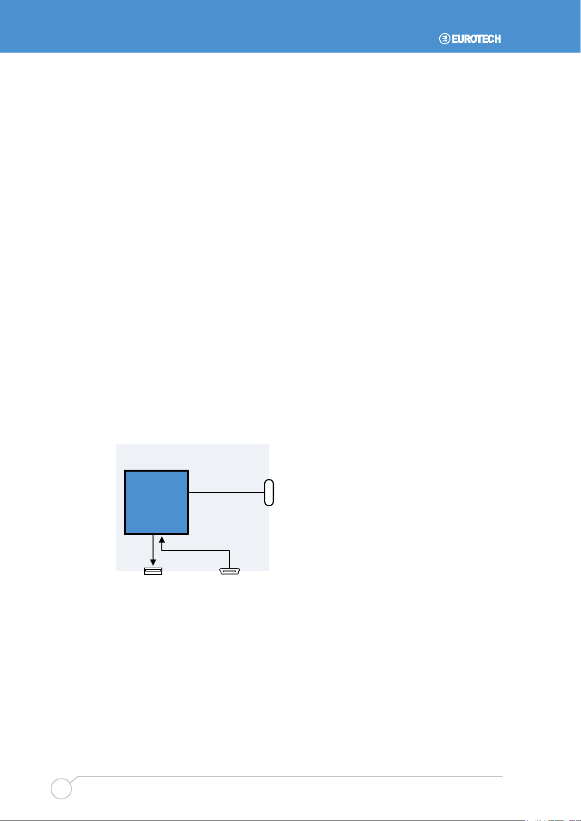
Standard Configuration
A standard GCM includes a USB 1.1 host port on socket J4, a USB 1.1 client port on
socket J12, and twelve PXA320 GPIOs on socket J21.
The following diagram illustrates a standard GCM.
12 GPIOs
J21
Graphics ClientM
PXA320
Processor
J4 J12
USB 1.1 Host USB 1.1 Client

Hardware Specification
110120-1000A 15
Volume Production Options
Three volume production options are available providing additional USB ports and a
Camera Sensor Interface (CSI). Contact your Eurotech sales representative if your
application requires one of these options.
The first option provides two USB 1.1 host ports on socket J4 (dual socket option) and a
USB 2.0 client port on socket J12. The USB 2.0 client interface uses ten of the twelve
GPIOs. In this option, only two GPIOs are available for application use on socket J21.
The following diagram illustrates the first volume production option.
Graphics ClientM
PXA320
Processor
J12
USB 2.0
UTMI
Transceiver
USB 2.0 Client
J4
USB 1.1 Host 1
USB 1.1 Host 2
2 GPIOs
J21
The second option provides a USB 1.1 host port on socket J4, a USB 1.1 client port on
socket J12, and a CSI on socket J21. The CSI uses ten of the twelve GPIOs. In this
option, only two GPIOs are available for application use on socket J21.
The following diagram illustrates the second volume production option.
CSI with 2 GPIOs
J21
Graphics ClientM
PXA320
Processor
J4 J12
USB 1.1 Host USB 1.1 Client

Graphics ClientM User Manual
110120-1000A
16
The third option provides two USB 1.1 host ports on socket J4 (dual socket option) and a
CSI on socket J21. The CSI uses ten of the twelve GPIOs. In this option, socket J12 is
not populated, and only two GPIOs are available for application use on socket J21.
The following diagram illustrates the third volume production option.
CSI with 2 GPIOs
J21
Graphics ClientM
PXA320
Processor
J4
USB 1.1 Host 1
USB 1.1 Host 2
Serial Ports
The PXA320 includes three serial ports which are available externally on the GCM. The
following table describes these serial interfaces.
Serial Header Description
Standard
Option
1
J15: Serial 1, page 38
EIA-232, 9-wire
J22: GPIO and Serial 1 (EIA-422/485), page 43
EIA422/485
2 J16: Serial 2, page 39 EIA-232, 5-wire 3.3V, 5-wire
3 J14: Serial 3, page 38 EIA-232, 5-wire 3.3V, 5-wire
Serial 1 interfaces to the PXA320 full-function UART supplying the full complement of
modem control signals. This port is available at EIA-232 levels on header J15 or at
EIA422/485 levels on header J22. The processor selects the mode of operation using a
control signal mapped to GPIO97.For further details, see PXA320 GPIO Cross-
Reference, page 11.
Serial 2 interfaces to the PXA320 IrDA UART.A standard GCM supports a 5-wire
interface at EIA-232 levels. A 3.3 V logic level volume production option supporting an
off-board IrDA transceiver is available. This option includes an additional 3.3 V logic level
enable signal and 3.3 V output.
Serial 3 interfaces to the PXA320 Bluetooth UART signals providing a 5-wire interface. A
standard GCM supports EIA-232 levels, while a 3.3 V logic level volume production
option supporting an off-board Bluetooth transceiver is available. This option includes an
additional 3.3 V logic level enable signal and 3.3 V output.

Hardware Specification
110120-1000A 17
Ethernet
An on-board Ethernet controller provides a 10/100 BT Ethernet port on J3, page 31.This
RJ-45 socket includes integrated magnetics and indicators. For a description of the
Ethernet LEDs, see LED Indicators, page 30.
SD/MMC Interface
Two Secure Digital and MultiMediaCard (SD/MMC) sockets enable mass storage and I/O
expansion on the GCM: J10, page 35 and J9, page 34. These interfaces support Secure
Digital Memory (SD), Secure Digital I/O (SDIO), MultiMediaCard (MMC), and
synchronous serial (SPI) modes of operation. SD and SDIO cards can run in 4-bit, 1-bit,
and SPI modes. MMC cards run in 1-bit or SPI modes. This manual lists the signals for
use in 4-bit SDIO mode. Operating system drivers may not be available for all modes of
operation. Contact your local Eurotech technical support for driver availability for the
operating system that you are using.
The following table illustrates how the signals are mapped differently depending on the
mode of operation. Signal names and types denote the direction of the signal relative to
the GCM. Notice that the SD standard references SPI-mode signals with respect to the
card with pin 2 of the SD header listed as "Data In". This manual and PXA320
documents reference the signals with respect to the socket. In the table, pin 2 is listed as
"Data Out".
SD Socket
Eurotech
Name
Description
Pin
Name
4-bit Mode
1-bit Mode
SPI Mode
1 DAT3 SD_DAT3 Data 3 IO unused - MMC_CS1# O
2 CMD SD_CMD Command IO Command IO Data Out O
3 VSS1 ground - P - P - P
4 VDD SD_PWR - PO - PO - PO
5 CLK SD_CLK Clock O Clock O Clock O
6 VSS2 ground - P - P - P
7 DAT0 SD_DAT0 Data 0 IO Data IO Data In I
8 DAT1 SD_DAT1 Data 1 IO Interrupt I Interrupt I
9 DAT2 SD_DAT2 Data 2 IO unused - MMC_CS0# O
Pin 9 of an SD/MMC card is unused in SPI mode. Chip Select 0 is shown in this row to
illustrate the alternate signal mapping to SD_DAT2.
Some SD sockets supply the following signals, which are not part of the SD/SDIO
standard. These signals are connected on sockets J9 and J10.
SD Socket Pin Eurotech Name Description Type
10 SD_CD# Card Detect I
11 SD_WP# Write Protect I
Power to the SD/MMC sockets is software-controlled. A standard GCM supports 3.3 V
cards. Support for 1.8 V cards is available as a volume production option.

Graphics ClientM User Manual
110120-1000A
18
CAN 2.0B Bus
The GCM supports a direct connection to a CAN (Controller Area Network) bus compliant
with the CAN 2.0B specification. The CAN 2.0B bus provided on header J23, page 44 is
driven by an on-board controller and includes a CAN transceiver, common mode filter,
and ESD protection.
1-Wire Bus
A 1-Wire bus provides a low-speed, single-wire communication bus to external devices.
Typically, this bus is used to communicate with small inexpensive devices such as
batteries and security components. The PXA320 supports a 1-Wire bus on header J11,
page 35.For electrical specifications, see PXA320 Processor, page 47.
I2C Bus
I2C (Inter-IC) is a multi-master, two-wire synchronous serial bus for communications
between integrated circuits and for addressing peripherals in a system. The bus master
addresses devices using the data line and provides a synchronous clock for reading and
writing devices. Client devices respond only when queried by the master device.
The GCM uses the PXA320 as the I2C bus master to communicate with on-board
devices. In addition, connector J21, page 40 includes an external connection to the I2C
bus.
The following diagram illustrates the I2C architecture on GCM. For electrical
specifications, see PXA320 Processor, page 47.
I2C_SDA
I2C_SCL
ADSmartIORTC
J21
Graphics ClientM
PXA320
Processor
3.3 V
1.2k 1.2k
The following table lists the addresses of the I2C devices.
Device Address Function
DS1307 1101 000 Real-time clock
ADSmartIO reserved Various I/O functions
The DS1307 supports a maximum bit rate of 100 kbps. Do not use the I2C bus at rates
faster than 100 kbps.
Hardware Specification
110120-1000A 19
User Interface and Display
The PXA320 includes an integrated PXA320 display controller to drive liquid crystal
displays (LCDs). These data and control signals, as well as display power, backlight
power and control, VEE adapter control, and touch panel signals are available on the
GCM.In addition, the GCM includes an audio subsystem providing an audio line in,
headphone output, and stereo speaker output.
Display
Displays are available in a variety of types and sizes and have a range of voltage and
data requirements. To meet these various requirements, the GCM provides a 16-bit
(565 RGB) LCD interface, an adjustable display power supply, and adjustable display
signal voltage levels.
The following table summarizes the display capabilities.
Feature Description
Resolution Up to 1024 x 768
Display Power 5 V (optional 3.3 V)
Display Buffer 3.3 V signal levels (optional 5 V)
Scan Direction Optional settings for PNL_RL (right-to-left) and PNL_UD
(up-and-down) signals for active displays
Contrast Control Contrast control of some passive displays
Features are set at time of production. Contact your local Eurotech technical support if
your application requires any of the volume production options.
The display interface is available on header J6, page 32. For electrical specifications,
see Display, VEE Adapter, and Backlight, page 49.
VEE Adapter
Many passive panels require a positive or negative bias voltage in the range of fifteen to
thirty volts to bias the passive LCD. Some displays include a VEE generator and require
a low-voltage analog signal to control the contrast.
The GCM supports an external VEE power supply adapter on header J7, page 33.This
header supplies power and three control signals driven by the PXA320 to the adapter
and receives VEE power from the adapter. For electrical specifications, see Display,
VEE Adapter, and Backlight, page 49.
The following table describes the VEE adapter control signals.
J7 Pin Name Type PXA320 Signal Description
3 VEE_CTL O GPIO4_2 VEE adapter on and off control
5 VCON O PWM1 Low-voltage contrast control
6 VPCLK O LPCLK Display controller pixel clock
Graphics ClientM User Manual
110120-1000A
20
Backlight
Most LCDs include one or more cold-cathode fluorescent lamp (CCFL) tubes to backlight
the displays. Backlight inverters drive the panel backlights. These circuits are typically
external to the display and generate the several hundred volts required to drive the CCFL
tubes. Backlights can easily become the greatest source of power consumption in a
portable system.
Typically, backlight inverters include control signals to dim and turn off the backlight. To
reduce power consumption, header J8, page 34 provides two backlight control signals
driven by the PXA320. For electrical specifications, see Display, VEE Adapter, and
Backlight, page 49.
The following table describes the backlight control signals.
J8 Pin Name Type
PXA320 Signal
Description
5 BKLT_ON# OD GPIO126 Turns power on or off
6 BKLT_PWM AO PWM0 Controls backlight intensity
For details about the backlight power, see Power Supply Architecture, page 25.
Touch Panel
The GCM supports a 4-wire or 5-wire resistive touch panel on header J5, page 32.
Standard GCMs use the integrated PXA320 touch screen controller to drive a 4-wire
touch panel. For electrical specifications, see PXA320 Processor, page 47. An on-board
5-wire controller is available as a volume production option.
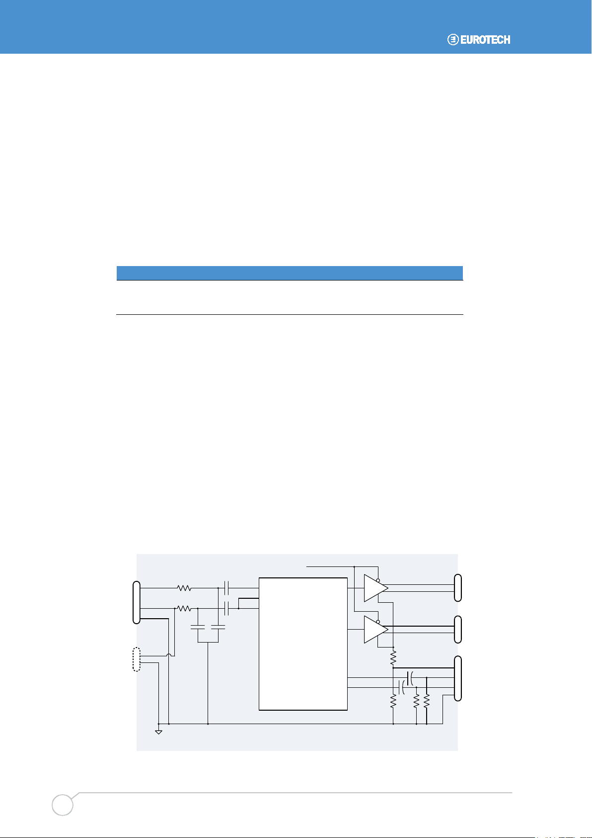
Audio Interface
For its audio subsystem, the GCM uses an AC '97 stereo codec combined with a dual
audio amplifier. This subsystem supports an audio line in, headphones, and stereo
speakers. For electrical specifications, see Audio Interface, page 52.
The following diagram illustrates the audio subsystem.
Graphics ClientM
J18 U
AC ’97 Codec
from PXA320
LINE_IN_L
LINE_IN_R
MIC1
AIN_R
AIN_L LINE_OUT_L
LINE_OUT_R
HP_R
HP_L
SPKL+
SPKL-
J18 L
J17
SPKR+
SPKR-
J19
HP_IN
J100
HP_OUT_R
HP_OUT_L
Audio or
Analog GND
Table of contents
Other Eurotech Motherboard manuals

Eurotech
Eurotech Titan User manual

Eurotech
Eurotech Vector User manual

Eurotech
Eurotech GEMINI 1U ICE User manual

Eurotech
Eurotech AIM104-COM8 User manual

Eurotech
Eurotech GEMINI User manual

Eurotech
Eurotech Bitsy G5 User manual

Eurotech
Eurotech Titan User manual

Eurotech
Eurotech ANTARES User manual

Eurotech
Eurotech Apollo User manual

Eurotech
Eurotech ALUDRA User manual


