Eurotherm 637 Series User manual

Series

Produkt-Handbuch Serie 637 V10.08STEH00 (UL: 7.2.8.3) 2Product manual Series 637 V10.08STEH00 (UL: 7.2.8.3)
DIGITALER SERVOREGLER
DIGITAL SERVO DRIVE
Typ / Model : 637/D6R+K D6R
Produkt-Handbuch
Product manual
ãEUROTHERM Antriebstechnik GmbH.
Alle Rechte vorbehalten. Kein Teil der Beschreibung darf
in irgendeiner Form,ohne Zustimmung der Gesellschaft
vervielfältigt oder weiter verarbeitet werden.
Änderungen sind ohne vorherige Ankündigung
vorbehalten.
EUROTHERM hat für seine Produkte teilweise Waren-
zeichenschutz und Gebrauchsmusterschutz eintragen
lassen. Aus dem Überlassen der Beschreibungen darf
nicht angenommen werden, daß damit eine Übertragung
von irgendwelchen Rechten stattfindet.
Hergestellt in Deutschland, 1998
ãEUROTHERM Drives Limited.
All rights reserved. No portion of this description may
be produced or processed in any form without the
consent of the company.
Changes are subject to change without notice.
EUROTHERM has registered in part trademark
protection and legal protection of designs. The handing
over of the descriptions may not be construed as the
transfer of any rights.
Made in Germany, 1998

Produkt-Handbuch Serie 637 V10.08STEH00 (UL: 7.2.8.3) 3Product manual Series 637 V10.08STEH00 (UL: 7.2.8.3)
Weitere Unterlagen,Further descriptions,
die im Zusammenhang mit that relate to this document.
diesem Dokument stehen.
Rack 6HE
R6 - Produkt-Beschreibung
UL:7.2.1.1/2
Rack 6U
R6 - Product Description
EMV-Rack 6HE
R6 EMV - Produkt-Beschreibung
UL:7.2.1.3
EMC rack 6U
R6 EMC - Product Description
Netz-Einschubmodul / 6HE
NE.. -3/-6 - Produkt-Beschreibung
UL:7.2.2.1/2
Power supply plug-in module / 6U
NE.. -3/-6 - Product Description
SERVOdrive - SUCOnet K
CAN - Interface
Profibus DP
Interbus S
UL:7.5.2/3/4/5 SERVOdrive - SUCOnet K
CAN Interface
Profibus DP
Interbus S
E/A - Interface
RP_EA - Produkt-Beschreibung
UL:7.5.7.2
I/O - Interface
RP_EA – Product Description
Entstörhilfsmittel - Produkt-Beschreibung
UL: 7.9.4.2
Supression aids - Product Description
Serielles Übertragungsprotokoll
EASY-seriell - Produkt-Beschreibung
UL: 10.6.3
Serial transfer protocol
EASY-serial - Product Description
EASYRIDER - Produkt-Beschreibung
UL: 10.6.4
EASYRIDER - Product Description
BIAS - Befehlsbeschreibung
UL: 10.6.5
BIAS - Command Description
Zubehör
UL: 12
Accessories

Produkt-Handbuch Serie 637 V10.08STEH00 (UL: 7.2.8.3) 4Product manual Series 637 V10.08STEH00 (UL: 7.2.8.3)
INHALTSVERZEICHNIS CONTENTS
Seite/Page
Das Wichtigste zuerst ........................................ The most important thing first......................7
Sicherheitshinweise............................................ Safety precautions.........................................8
1 Allgemeines............................................ General Information...................................10
1.1 Systembeschreibung...........................................System description.................................................... 10
1.1.1 Digitale Kommunikation ....................................Digital communication ............................................. 11
1.1.2 Betriebskonfigurationen .....................................Operation configurations ......................................... 11
1.1.3 Kompatibilität zu Analogregler FRR AC S........Compatibility to analog regulator FRR AC S .......... 12
1.2 Typenschlüssel ...................................................Key to the models...................................................... 14
1.2.1 Beispiel...............................................................Example .................................................................... 14
1.3 Bemessungsdaten................................................Range data................................................................ 15
1.3.1 Isolierungskonzept..............................................Insulation concept .................................................... 15
1.3.2 Generelle Daten..................................................General data............................................................. 15
1.3.3 Kompaktgeräte 637/K D6R................................Compact units 637/K D6R........................................ 16
1.3.4 Einschubmodule 637/D6R..................................Plug-in modules 637/D6R ........................................ 17
1.3.5 Einphasen- und Dreiphasenversorgung..............Single- and three-phase supply ................................ 18
1.3.6 Ausgangsleistung................................................Output power ............................................................ 19
1.4 Abmaße und Lageplan........................................Dimensions and layout ............................................. 20
1.4.1 Abmaße für Kompaktgerät .................................Dimensions for compact device
und Einschubmodul ............................................and plug-in module................................................... 20
1.4.2 EMV-Bügel (optional)........................................EMC bow (optional) ................................................. 21
1.4.2.1 für 8 TE - Regler.................................................for 8 HP drive........................................................... 21
1.4.2.2 für 16 TE - Regler...............................................for 16 HP drive......................................................... 21
1.4.3 Lageplan .............................................................Layout ....................................................................... 22
1.4.3.1 Lageplan Controller- Platine ..............................Layout of controller board ....................................... 22
1.4.3.2 Lageplan Power- Platine.....................................Layout of power board ............................................. 22
2 Anschlußbelegung................................. Connector assignment
und Funktionen..................................... and functions...............................................23
2.1 Übersicht der Anschlüsse ...................................General view of connections .................................... 23
2.1.1 vom Kompaktgerät K D6R 02...10.....................of the compact device K D6R 02 - 10 ....................... 23
2.1.2 vom Kompaktgerät K D6R 16...30.....................of the compact device K D6R 16 - 30 ....................... 24
2.2 Steckerbelegungen und.......................................Connector pin assignments
Kontaktfunktionen..............................................and contact functions................................................ 25
2.2.1 Leistungsanschlüsse ...........................................Power connections.................................................... 25
2.2.1.1 für Einschubmodul D6R.....................................for plug-in module D6R............................................ 25
2.2.2 Signalanschlüsse.................................................Signal connections.................................................... 26
2.2.2.1 Steuersignalstecker X10 .....................................Control signal plug X10 ........................................... 26
2.2.2.1.1 Komplette Darstellung X10........................................Complete representation X10 ............................................26
2.2.2.1.2 Anschlußbeispiel ........................................................Connection example...........................................................27
2.2.2.1.3 Ein- /Ausgänge...........................................................Inputs / outputs ..................................................................28
2.2.2.2 Resolver..............................................................Resolver .................................................................... 29
2.2.2.2.1 Funktionen der Resolverauswertung ..........................Functions of the resolver evaluation..................................29
2.2.2.2.2 Resolveranschlüsse X30.............................................Resolver connections X30..................................................29
2.2.2.3 Multifunktion X40..............................................Multi-function X40 ................................................... 30
2.2.2.3.1 Beschreibung X40......................................................Description X40 .................................................................30
2.2.2.3.2 Inkremental-Ausgang .................................................Incremental output.............................................................31
2.2.2.3.3 Inkremental-Eingang ..................................................Incremental intput..............................................................32
2.2.2.3.4 Schrittmotor - Eingang Puls / Richtung......................Stepper motor input pulse / direction.................................33
2.2.2.3.5 Schrittmotor - Eingang Puls positiv / negativ.............Stepper motor input pulse positive / negative ....................33
2.2.3 Digitale Schnittstellen ........................................Digital interfaces...................................................... 34
2.2.3.1 Service-Schnittstelle COM1 (RS232) ................Service interface COM1 (RS232) ............................. 34

Produkt-Handbuch Serie 637 V10.08STEH00 (UL: 7.2.8.3) 5Product manual Series 637 V10.08STEH00 (UL: 7.2.8.3)
INHALTSVERZEICHNIS CONTENTS
Seite/Page
2.2.3.2 Feldbus-Schnittstelle COM2.............................. Fieldbus interface COM2......................................... 35
2.2.3.3 zusätzliche E/A´s................................................ additional In-/Outputs.............................................. 35
2.2.3.4 Steckerbelegung für RS232................................ Pin assignment for RS232 ........................................ 36
2.2.3.5 Steckerbelegung für RS422/485......................... Pin assignment for RS422/485 ................................. 36
2.2.3.6 Steckerbelegung für CAN .................................. Pin assignment for CAN........................................... 37
2.2.3.7 Steckerbelegung für Profibus DP....................... Pin assignment for Profibus DP............................... 37
2.2.3.8 Steckerbelegung für SUCOnet K ....................... Pin assignment for SUCOnet K................................ 37
2.2.3.9 Steckerbelegung für Interbus S .......................... Pin assignment for Interbus S .................................. 38
2.2.3.10 Steckerbelegung für E/A-Interface..................... Pin assignment for I/O interface .............................. 39
2.2.3.11 Steckerbelegung für E/A-Interface..................... Pin assignment for I/O interface .............................. 40
3 Betriebsarten..........................................Operating modes ......................................... 41
3.1 Betriebsarten und Kontaktfunktionen ................ Operating modes and pin functions ......................... 42
3.2 Konfigurierbare Kontaktfunktionen................... Configurable pin-functions ...................................... 43
3.3 Funktionsdiagramme von Ein- .......................... Function diagrams from inputs
und Ausgängen ................................................... and outputs ............................................................... 44
4 Mechanische Installation ......................Mechanical installation .............................. 45
4.1 Montage.............................................................. Mounting .................................................................. 45
4.2 Schaltschrank - Einbau....................................... Control cabinet - mounting ...................................... 45
4.3 Kühlung und Belüftung...................................... Cooling ..................................................................... 46
5 Elektrische Installation.........................Electrical installation.................................. 47
5.1 Sicherheit............................................................ Safety ........................................................................ 47
5.2 Gefahr elektrischer Schläge ...............................The danger of electric shocks................................... 47
5.3 Gefahrenbereiche ............................................... Danger areas............................................................ 47
5.4 Erdung, Sicherheitserdung ................................. Grounding, safety grounding ................................... 47
5.4.1 Erdungsanschlüsse ............................................. Ground connections ................................................. 48
5.5 Kurzschlußfestigkeit und Ableitströme.............. Short-circuit capability and discharge currents ...... 48
5.6 Sicherungen, Schütze, Filter............................... Fuses, contactors, filters .......................................... 49
5.7 Korrektur des Eingangstroms............................. Correction of supply current .................................... 51
5.8 Auslegung des Ballastwiderstandes ................... Selection of the brake resistor.................................. 52
6 Verdrahtungshinweise ..........................Wiring instructions ..................................... 54
6.1 Allgemeines........................................................ General Information................................................. 54
6.2 Steuersignalverdrahtung..................................... Control cabling ........................................................ 54
6.3 Leistungssignalverdrahtung................................ Power cabling .......................................................... 54
6.4 Rack - Montage .................................................. Installation of the rack ............................................. 54
6.5 Analoger Sollwert .............................................. Analog setpoint......................................................... 55
6.6 Sicherheitsregeln ................................................ Safety rules ............................................................... 55
6.7 Elektromagnetische Verträglichkeit (EMV) ...... Electromagnetic compatibility (EMC) ..................... 55
6.7.1 Montagehinweise ............................................... Hints for mounting ................................................... 56
6.7.2 Montagebeispiel ................................................. Example for mounting .............................................. 57
6.7.3 Eingehaltete Normen, Grenzwerte ..................... Achieveable specifications
und Rahmenbedingungen ................................... and conditions .......................................................... 58
7 Parametrierung und..............................Setting and
Programmierung ...................................programming............................................... 59
7.1 Jumper ................................................................ Jumper...................................................................... 59
7.2 Digitale Kommunikation.................................... Digital communication............................................. 60
7.3 PROG-Taster-Funktionen................................... PROG-key functions................................................. 60
7.3.1 Beschreibung zu PROG-Taster .......................... Description for PROG-key....................................... 60
7.3.2 Bedienung des PROG-Tasters............................ Operating via PROG-key ......................................... 61

Produkt-Handbuch Serie 637 V10.08STEH00 (UL: 7.2.8.3) 6Product manual Series 637 V10.08STEH00 (UL: 7.2.8.3)
INHALTSVERZEICHNIS CONTENTS
Seite/Page
8 Inbetriebnahme..................................... Commissioning............................................62
8.1 Voraussetzungen.................................................Preparations ............................................................. 62
8.2 Inbetriebnahme in Schritten ...............................Commissioning in steps ............................................ 63
9 Diagnose und Fehlersuche ................... Diagnosis and trouble shooting..................66
9.1 7-Segment-Anzeige ............................................7-segment display ..................................................... 66
9.2 Reset eines Reglerfehlers ...................................Reset of a regulator trouble...................................... 68
9.3 Fehlersuche.........................................................Trouble shooting....................................................... 69
10 Blockschaltbild...................................... Block circuit diagram..................................70
11 Allgemeine technische Daten ............... General technical data................................71
11.1 Leistungsteil .......................................................Power circuit ............................................................ 71
11.2 Steuerungsteil .....................................................Control circuit .......................................................... 71
11.3 Signal Ein- und Ausgänge, Anschluß X10.........Signal inputs and outputs, connection X10 .............. 71
11.4 Digitale Regelung...............................................Digital control .......................................................... 72
11.5 Digitale Kommunikation ....................................Digital communication ............................................. 72
11.6 Resolverauswertung/Transmitterprinzip ............Resolver evaluation/transmitter principle................ 72
11.7 Controllersystem.................................................Controllersystem ...................................................... 73
11.8 Meßbuchsen MP1 und MP2 ...............................Measuring sockets MP1 and MP2............................ 73
11.9 Thermische Daten...............................................Thermal data ............................................................ 73
11.10 Mechanische Daten ............................................Mechanical data ....................................................... 73
12 Entsorgung ............................................ Disposal .......................................................73
13 Software................................................. Software.......................................................74
13.1 EASYRIDER <.................................................EASYRIDER <......................................................... 74
13.2 BIAS-Befehle .....................................................BIAS commands........................................................ 75
13.3 Erweiterte BIAS-Befehle ...................................Extended BIAS-commands........................................ 78
14 Index ...................................................... Index ............................................................79
15 Zertifikate.............................................. Certificates...................................................82
16 Änderungsliste ...................................... Modification Record ...................................90

Produkt-Handbuch Serie 637 V10.08STEH00 (UL: 7.2.8.3) 7Product manual Series 637 V10.08STEH00 (UL: 7.2.8.3)
Das Wichtigste zuerst The most important thing first
Wir bedanken uns für das Vertrauen,
das Sie unserem Produkt entgegenbringen.
We thank you for the trust that you have
shown in our product.
Die vorliegende Betriebsanleitung dient der
Übersicht von technischen Daten und
Eigenschaften.
Bitte lesen Sie vor Einsatz des Produktes
diese Bedienungsanleitung.
Bei Rückfragen wenden Sie sich bitte an
Ihren nächsten Eurotherm-Ansprechpartner.
The operating instructions presented here
serves as an overview of the technical data
and features.
Please read the operating instructions before
putting the product to use.
If you have any questions, please contact your
nearest Eurotherm representative
Der nicht sachgemäße Einsatz des Produktes
im Zusammenhang mit lebensgefährlicher
Spannung kann zu Verletzungen führen.
Des weiteren können dadurch
Beschädigungen an Motoren oder Produkten
auftreten. Berücksichtigen Sie deshalb bitte
unbedingt unsere Sicherheitshinweise.
Thema: Sicherheitshinweise
Wir gehen davon aus, daß Sie als Fachmann
mit den einschlägigen Sicherheitsregeln,
insbesondere nach VDE 0100, VDE 0113,
VDE 0160, EN 50178 den Unfallverhütungs-
vorschriften der Berufsgenossenschaft und
den DIN-Vorschriften vertraut sind und mit
ihnen umgehen können.
Des weiteren sind die CE - Bestimmungen
einzuhalten und sicherzustellen.
Je nach Einsatzart sind weitere nationale
Normen, wie z. B. UL, DIN zu beachten.
Wenn der Einsatz unserer Produkte im
Zusammenhang mit Komponenten anderer
Hersteller erfolgt, sind auch deren
Betriebsanleitungen unbedingt zu beachten.
Improper application of the product in
connection with dangerous voltage, can lead
to injuries.
In addition, damage can also occur to motors
or other products.
Therefore please observe strictly our safety
precautions.
Topic: Safety precautions
We assume that as an expert, you are familiar
with the relevant safety regulations, especially
in accordance with VDE 0100, VDE 0113,
VDE 0160, EN 50178, the accident prevention
regulations of the employers liability insurance
company and the DIN regulations and that you
can use and apply them.
Also the CE - regulations are to be observed
and guaranteed.
Depending on the kind of application, additional
norms e.g. UL, DIN are to be observed.
If our products are employed in connection with
components from other manufacturers, their
operating instructions are also to be strictly
observed.

Produkt-Handbuch Serie 637 V10.08STEH00 (UL: 7.2.8.3) 8Product manual Series 637 V10.08STEH00 (UL: 7.2.8.3)
Sicherheitshinweise Safety precautions
!Achtung ! !Attention !
Bei den digitalen Servoreglern handelt es sich im
Sinne der VDE 0160 um ein elektrisches
Betriebsmittel der Leistungselektronik (BLE) zur
Regelung des Energieflusses in Starkstromanlagen.
Sie sind ausschließlich zur Speisung von
Eurotherm- (oder von Eurotherm freigegebenen)
Servomotoren bestimmt.
Das Handling, die Montage, der Betrieb und die
Wartung sind nur unter der Bedingung und
Einhaltung der gültigen und/oder gesetzlichen
Vorschriften, Regelwerke und dieser technischen
Dokumentation zulässig.
The digital servo drives are in the sense of VDE
0160 power electronic equipments for regulating
the flow of energy in electrical power installations.
They are exclusively for supplying Eurotherm
(or Eurotherm approved) servomotors.
Handling, installation, operation, and maintenance
are only permitted under the conditions of and in
keeping with the effective and/or legal regulations,
regulation publications and this technical
document.
Die strikte Einhaltung dieser Regelwerke
ist vom Betreiber sicherzustellen.
The operator must make sure that these
regulations are strictly followed.
Konzept der galvanischen Trennung und
Isolation:
Concept of the galvanic separation and
insulation:
Galvanische Trennung und Isolation entsprechen
der VDE 0160 und der verstärkten Isolation.
Galvanically separation and insulation correspond
to VDE 0160 and the amplified insulation.
Zusätzlich sind alle digitalen Signal-Ein- und
Ausgänge entweder als Relais oder über Opto-
Koppler galvanisch getrennt. Dadurch wird eine
erhöhte Störsicherheit und Schadensbegrenzung
im Falle externer Fehlanschlüsse erreicht.
In addition all digital signal inputs and outputs are
galvanically separated either as a relay or via opto
coupler. In this way an increased interference
security and the limitation of damages in case of
external incorrect connections is given.
Die Spannungspegel dürfen die Sicherheits-
kleinspannung von 60V DC bzw. 25V AC gemäß
VDE 0160 nicht überschreiten.
The voltage level must not exceed the low safety
voltage 60V DC or 25V AC, respectively in
accordance with VDE 0160.
Die in weiteren Abschnitten (Punkten)
aufgeführten Sicherheitshinweise und Angaben
sind vom Betreiber einzuhalten.
The operator must make sure that these regulations
are strictly followed.
Gefahr !
Hohe Berührungsspannung !
Schockgefahr !
Lebensgefahr !
Danger !
High contact voltage !
Danger of getting shocked !
Danger to your life !
!Vorsicht ! !Caution !
Ein Öffnen der Servoregler durch den
Betreiber ist aus Sicherheits- und Gewähr-
leistungsgründen nicht zulässig. Die Voraus-
setzung für eine einwandfreie Funktion des
Servoreglers ist die fachgerechte Projektierung
!
Opening the servo drive by the operator is
prohibited due to reasons of safety and
guarantee. The requirement for problem-free
operation of the servo drive is the expert
configuring !

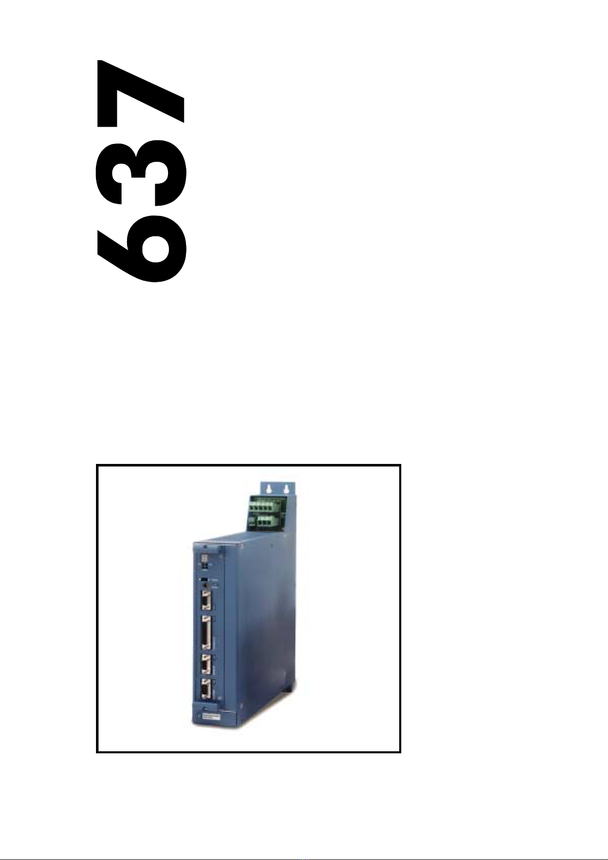
Produkt-Handbuch Serie 637 V10.08STEH00 (UL: 7.2.8.3) 9Product manual Series 637 V10.08STEH00 (UL: 7.2.8.3)
Sicherheitshinweise Safety precautions
Bitte beachten ! Please observe !
Achten Sie vor allem darauf:
Zulässige Schutzklasse: Schutzerdung,
Betrieb nur mit vorschriftsmäßigem
Anschluß des Schutzleiters zulässig.
Der Betrieb des Servoreglers unter alleiniger
Verwendung einer Fehlerstrom-
Schutzeinrichtung als Schutz bei indirektem
Berühren ist nicht zulässig.
Der Servoregler darf nur im Rack oder im
Kompaktgehäuse eingesetzt werden. Des
weiteren ist der Regler ausschließlich für den
Schaltschrankbetrieb konzipiert.
Arbeiten am und mit dem Servoregler dürfen
nur mit isoliertem Werkzeug durchgeführt
werden.Installationsarbeiten dürfen nur im
spannungsfreien Zustand erfolgen. Bei
Arbeiten am Antrieb nicht nur den Aktiv-
Eingang sperren, sondern den kompletten
Antrieb vom Netz trennen.
ACHTUNG - Stromschlaggefahr, nach dem
Ausschalten 3 Minuten Kondensator-
entladezeit einhalten.
Lackversiegelte Schrauben erfüllen wichtige
Schutzfunktionen und dürfen weder betätigt
noch entfernt werden. Es ist nicht erlaubt, mit
Gegenständen jeglicher Art in das
Geräteinnere einzudringen.
Bei der Montage oder sonstigen Arbeiten im
Schaltschrank ist das Gerät gegen
herunterfallende Teile (Drahtreste, Litzen,
Metallteile usw.) zu schützen. Metallteile
können innerhalb des Servoreglers zu einem
Kurzschluß führen.
Vor der Inbetriebnahme sind zusätzliche
Abdeckungen zu entfernen, damit es zu
keiner Überhitzung des Gerätes kommen
kann. Bei Messungen am Servoregler ist
unbedingt auf Potentialtrennung zu achten!
Especially to be complied with:
The class of protecton which is permitted:
protective grounding; operation is only
permitted when the protective conductor is
connected according to regulations.
The operation of servo drives is not allowed
under the sole use of a residual current
operated protective device as protection
against indirect touching.
The servo drive may only be used in the rack
or in its compact enclousure. Furthermore
the regulator is designed solely for control
cabinet operation.
Work on or with the servo drive may only be
carried out with insulated tools.
Installation work may only be done in a
deenergized state. When working on the
drive, do not only block the Aktiv-input but
separate the complete drive from the mains.
CAUTION - risk of electrical shock, wait 3
minutes after switching off, for discharging
the capacitors.
Screws sealed with varnish fulfill an
important protection function and may not be
moved or removed.
It is prohibited to penetrate the inside of the
unit with objects of any kind.
Protect the unit from falling parts (pieces of
wire, fley, metal parts, etc.) during
installation or other work in the control
cabinet. Metal parts can lead to a short in
the servo drive.
Before putting into operation, remove
additional covers so that the unit does not
overheat. With measurements at the servo
drive it is absolutely necessary to observe the
potential separation!
STOP Stop !
Für Schäden, die aufgrund einer
Nichtbeachtung der Anleitung oder
der jeweiligen Vorschriften entstehen,
übernimmt Eurotherm Antriebs-
technik GmbH keine Haftung !!
STOP Stop !
Eurotherm Drives Limited is not
liable for damages whith occur
by not following the instructions
or the applicable regulations !!

Produkt-Handbuch Serie 637 V10.08STEH00 (UL: 7.2.8.3) 10 Product manual Series 637 V10.08STEH00 (UL: 7.2.8.3)
1 Allgemeines General Information
1.1 Systembeschreibung System description
Der Digitale Servoregler dient der Strom-,
Drehzahl- und Lageregelung von
AC Servomotoren mit Resolver.
The digital servo drive serves to regulate the
current, speed and position of
AC servo motors with resolver.
Alle Regelkreise und Funktionen sind digital
realisiert.
All servo controls and functions are realized
digitally.
Systemvarianten System variants
Rack-Version: 637/D6R....
Rack version: 637/D6R....
Kompakt-Version: 637/K D6R....
Compact version: 637/K D6R....
M
Anschlußspannung:
Supply voltage:
DC-Zwischenkreis
DC-BUS Ucc
Us 24V DC
637/D6R
AC
DC
NEB...
M
optional R
1*oder 3*230VAC/50..60Hz
3*400...460VAC/50..60Hz 24V DC
637/D6R
M
637/K D6R
AC
DC
Us 24VDC
R
Anschlußspannung:
Supply voltage:
1*oder 3*230VAC/50..60Hz
3*400...460VAC/50..60Hz
Lüfter /
XN 1
6
5
4
3
2
1
NE... o
o
o
o
o
o
o
o
o
o
o
o
o
o
o
o
o
o
o
o
o
o
o
o
o
o
o
o
o
o
o
o
Netzeinschub-
modul, NE
P
ower-suppl
y
p
lug-in module
fan
Rack, R6
o
o
o
o
o
o
o
o
Lüfter /
Regler
Netzteil
Power supply unit
Fan
Erläuterungen zu Rack und Netzteilmodulen sind in
gesonderter Beschreibung dokumentiert.
Explanations to rack and power supply modules are
documented in separate description.
Bei Bedarf kann die rückgeführte Brems-
energie in zusätzliche externe Ballastwider-
stände abgeführt werden.
If required, the returned braking energy can
be drawn off into additional external ballast
resistors.
Die AC-Anschlußspannung wird direkt oder
über einen Trafo dem zugehörigen Netzteil
zugeführt.
The AC-supply voltage is fed directly or via
transformer to the associated power supply
module.
Die Geräte sind zum Betrieb an mittel-
punktgeerdeten Netzen (TN-Netzen)
vorgesehen !
The devices are designed to be operated on
networks which are grounded on centre
point (TN networks) !

Produkt-Handbuch Serie 637 V10.08STEH00 (UL: 7.2.8.3) 11 Product manual Series 637 V10.08STEH00 (UL: 7.2.8.3)
Systembeschreibung System description
1.1.1 Digitale Kommunikation Digital communication
Diagnose
Generell: durch 7-Segment-Anzeige
Komfortabel: durch PC mit EASYRIDER <
(serielle Schnittstelle RS232)
Parametrierung
Low-Level: durch Prog.-Taster auf der
Frontseite
Komfortabel: durch PC mit EASYRIDER <
(serielle Schnittstelle RS232)
Diagnosis
General: by 7-segment display
Comfortable: via PC by EASYRIDER <
(serial interface RS232)
Setup
Low Level: by Prog.-key on the front side
Comfortable: via PC by EASYRIDER <
(serial interface RS232)
Kommunikation Communication
Das serielle Übertragungsprotokoll ist offen
dokumentiert.
(Erläuterung siehe gesonderte Dokumentation)
Der Anwender hat Zugang zu allen Funktionen
und Parametern.
The serial-communication-protocol is free
documented.
(Explanation see seperate documentation)
Every user has unrestricted acces to all
functions and parameters.
EASYRIDER
Kundensoftware
custom-made software
SPS Software
PLC Software
SPS, binäre Satzwahl,+-10V
PLC, binary selection,+-10V X10
RS232,
RS422,
RS485,
CAN-Bus,
Profibus DP,
637/D6R
=
Stromregler
Drehzahlregler
Lageregler
current-loop
speed-loop
position-loop
7
:
FBedienung
instructions xProgrammierung
programming
$Diagnose
diagnostics ?Parametrierung
setup
F$
Fx
$?
Fx
$?°
o
SPS
PLC
SUCOnet K,
Interbus S
COM1
COM2
Fx
$?
RS232,
......
637/K D6R+
1.1.2 Betriebskonfigurationen Operation configurations
Die Möglichkeiten reichen von einfacher
Strom- und Drehzahlregelung bis hin zu frei
programmierbaren, lagegeregelten Abläufen
(SPS) mit Hilfe der 1500 BIAS-Befehlsätze.
(siehe Kapitel 3 und 13.2)
The possibilities range from simple current and
speed control to programmable position control
processes (PLC) supported by the 1500 BIAS-
command blocks.
(see chapter 3 and 13.2)

Produkt-Handbuch Serie 637 V10.08STEH00 (UL: 7.2.8.3) 12 Product manual Series 637 V10.08STEH00 (UL: 7.2.8.3)
Systembeschreibung System description
1.1.3 Kompatibilität zu Eurotherm- Compatibility to Eurotherm-
6 HE Analogregler FRR AC S 6 U analog regulator FRR AC S
(Nicht relevant bei Neuprojekten) (Not required for new projects)
Die digitalen Servoregler sind weitgehend
pin- und funktionskompatibel zu den analogen
Geräten der Serie FRR AC S.
Die EASYRIDER <- Software gestattet die
Anpassung an Ihre bestehende Ausstattung.
(siehe Kapitel 3)
Weitere Anpassungen erfolgen über
Jumpereinstellungen (siehe Kapitel 7.1)
The digital servo drives are to a great extent
pin- and function compatible to the analog
devices of the FRR AC S series.
The EASYRIDER <software allows the
adaption to your existing equipment.
(see chapter 3)
Further adaptions can be done by solder-
jumpers (see chapter 7.1)
Kompatibilitätseinschränkungen: Compatibility restrictions:
Einschränkung Restriction
1 Externe Stromlimitierung
durch Analogeingang an X10.19
Im PC-Konfigurations-Menue kann die
Funktion Drehzahlreglerparameter (frei
normierbar) aktiviert werden. In wenigen
Fällen wurde der bei FRR AC S interne
Pull-Up-Widerstand mit einem externen
Pull-Down-Widerstand belastet, um eine
Stromreduzierung zu erreichen. Der Pull-
Up-Widerstand im D6R+K D6R läßt sich
über die Lötbrücke JP101 aktivieren.
1 External current limiting
due to analog input at X10.19
In the PC configuration menu the function
speed regulator parameter (freely scaled)
can be activated. In few cases the internal
Pull-Up resistor with FRR AC S was
loaded with an external Pull-Down
resistor in order to reach a current
limiting. The Pull-Up resistor on the
D6R+K D6R can be activated via the
solder strip JP101.
2 Inkrementalgeberausgang-
Nullpunktverschiebung
Bei FRR AC S war eine Nullpunktver-
schiebung durch DIP-Schalter möglich.
Diese Funktion ist beim 637/D6R+K D6R
nicht realisiert.
2 Incremental encoder output-zero offset
With FRR AC S a zero drift was possible
by means of DIP switch. This function is
not realized with 637/D6R+K D6R.
3 Temp.-Überwachungs-Ausgang T2
(nur bei FRR AC S mit entsprechender
Optionsschaltung)
Das Signal T2 wird nicht mehr ausgegeben.
3 Temperature monitoring output T2
(only with FRR AC S with corresponding
option circuit)
T2 is no more signalized.
4 Bezugspotential
für alle digitalen Ein- und Ausgänge an
X10 ist jetzt X10.9.
4 Reference potential
all digital in- and output signals on X10
are referred to X10.9.

Produkt-Handbuch Serie 637 V10.08STEH00 (UL: 7.2.8.3) 13 Product manual Series 637 V10.08STEH00 (UL: 7.2.8.3)
Systembeschreibung System description
Kompatibilität zu Eurotherm- Compatibility to Eurotherm-
6 HE Analogregler FRR AC S 6 U analog regulator FRR AC S
(Nicht relevant bei Neuprojekten) (Not required for new projects)
Einschränkung Restriction
5 Temp.-Überwachung PTC
(nur bei FRR AC S mit entsprechender
Optionsschaltung)
Vor Abschaltung wird ca. 3 Sekunden das
Signal "WARNUNG" ausgegeben.
5 Temperature monitoring PTC
(only with FRR AC S with corresponding
option circuit)
Before switching off for approx 3 seconds
"WARNING" is signalized.
6 Reset
Der Anschluß X10.2 ist nicht mehr mit
der Resetfunktion belegt.
6 Reset
Connector X10.2 is no more assigned
with reset function.
7 n/I-Umschaltung
Anschluß X10.11 ist nicht mehr Bezugs-
potential für n/I-Umschaltung sondern
X10.9.
7 n/I-Switch over
Connector X10.11 is not reference
potential for n/I-switch over anymore, but
X10.9.
8 Warnung
Anschluß X10.7 ist nicht mehr
Bezugspotential für Warnungsausgang
sondern X10.9.
8 Warning
Connector X10.7 is not reference
potential for warning output anymore,
but X10.9.
9Die maximale Betriebsspannung an
allen Signalausgängen von X10 beträgt
DC 45V.
9The max. operating voltage on all signal
outputs of X10 is DC 45V DC.
10 Pin 26 an X50 ist intern nicht belegt und
muß frei bleiben !
10 Pin 26 on X50 is not assigned internally
and must be free !
Es kann nicht vollständig ausgeschlossen
werden, daß bei Sonderausführungen von
FRR AC S - Geräten zusätzliche Anpassungen
vorgenommen werden müssen.
One cannot completely rule out the possibility
that with special designs of FRR AC S devices
additional adjustments have to be made.

Produkt-Handbuch Serie 637 V10.08STEH00 (UL: 7.2.8.3) 14 Product manual Series 637 V10.08STEH00 (UL: 7.2.8.3)
1.2 Typenschlüssel Key to the models
Standard optional
Kennung
Marking a b c d e f g
Typ:
Model: XXX/ X D6R XX .S3 -X -X -XXX
Beschreibung Kennung
Marking Description
XXX/ = 637 ≅Eurotherm-Ausführung (blau), ohne
Angabe ≅ASB-Ausführung (weiß/rot)
XXX/ = 637
≅
Eurotherm-design (blue), without
information
≅
ASB-design (white/red)
K = 1-Achs-Kompakt
Digital-Servoregelsystem
= (entfällt bei Ausführung als Einschubgerät)
aK = 1 axis compact
digital servo drive system
= (is not used with model plug-in device)
D6R = Digitaler 6HE Regler bD6R = Digital 6U Regulator
Reglernennstrom:
02 = 2 Ampere
04 = 4 Ampere
06 = 6 Ampere
10 = 10 Ampere
16 = 16 Ampere
22 = 22 Ampere
30 = 30 Ampere
cRated current:
02 = 2 amperes
04 = 4 amperes
06 = 6 amperes
10 = 10 amperes
16 = 16 amperes
22 = 22 amperes
30 = 30 amperes
.S3 = Digitalregler 3. Generation d.S3 = Digital drive 3 rd generation
Zwischenkreisnennspannung:
-3 = 325V (230V AC)
-7 = 650V (460V AC)
eIntermediate circuit rated voltage:
-3 = 325V (230V AC)
-7 = 650V (460V AC)
-E = mit EMV-Bügeleinheit f-E = with EMC bow unit
im Regler:
zusätzliche Kommunikation über COM2
-232 = RS 232 Schnittstelle
-422 = RS 422 Schnittstelle
-485 = RS 485 Schnittstelle
-CAN = CAN-Bus
-SUC = SUCOnet K
-PDP = Profibus DP
-IBS = Interbus S (Achtung: geänderte Frontplatte)
–EA5 = E/A - Interface (5E, 2A) COM2
–EAE = E/A - Interface (14E, 10A) X200
–XXE = Kombination aus Komunikations-Interface
und E/A-Interface EAE (erste zwei Stellen
vom Kom.-Interface + E für E/A-Interface EAE)
gon the drive:
additional communication via COM2
-232 = RS 232 interface
-422 = RS 422 interface
-485 = RS 485 interface
-CAN = CAN bus
-SUC = SUCOnet K
-PDP = Profibus DP
-IBS = Interbus S (Attention: changed front plate)
–EA5 = I/O interface (5 I, 2 O) COM2
–EAE = I/O interface (14 I, 10 O) X200
–XXE = Combination of communication interface
and I/O interface EAE (the first two places
of com.-interface + E for I/O-interface EAE)
1.2.1 Beispiel Example
Musterbeispiel für die Bestellangabe eines 1-Achs- Typical example of an order of a 1-axis-
Kompaktgerätes in Eurotherm-Ausführung: compact device in Eurotherm-design:
Typ: 637/K D6R 02.S3-7-CAN Model: 637/K D6R 02.S3-7-CAN
637/ = Eurotherm-Ausführung (blau) 637/ = Eurotherm-design (blue)
K = 1-Achs-Kompaktgerät K = 1 axis compact device
D6R = Digitaler 6HE Regler D6R = Digital 6U Regulator
02 = 2 Ampere 02 = 2 amperes
.S3 = Digitalregler 3. Generation .S3 = Digital drive 3rd generation
-7 = 650V UCCN -7 = 650V UCCN
-CAN = CAN-Bus -CAN = CAN-Bus

Produkt-Handbuch Serie 637 V10.08STEH00 (UL: 7.2.8.3) 15 Product manual Series 637 V10.08STEH00 (UL: 7.2.8.3)
1.3 Bemessungsdaten Range data
1.3.1 Isolierungskonzept Insulation concept
COM1
COM2
Remote IN
X10
analog
X10
digital
X40
X30
gem. RP-Modul
dep. on RP-Mod.
M1, M2, M3
DC-Bus
Ballast
L1, L2, L3
Us DC 24 V
Netzteil
DC 24 V
PE
Power-Supply
Break-cirquit
L1
N
AC
Leistungsanschlüsse
Power-Terminals
doppelte Isolierung gem. VDE 0160
Netzteilisolation
Erforderlich für sichere Trennung (PELV): doppelte Isolation
ACHTUNG ! Der Isolationsgrad der Steuerelektronik (COM1..X40) entspricht der Isolation des Netzteils
Zusatzisolation über Opto-Koppler oder Relais (keine Schutzisolation)
double insulation ( VDE 0160)
Insulation of control voltage supply
Required for safe separation (PELV): double insulation
Take Care ! The insulation of control (Com1..X40) depends on the insulation of control voltage supply
Additional insulation via opto-coupler or relay (without Safety-Functions)
customer part
Kundenseitig
1)
1) siehe zusätzliche Hinweise, Kapitel 2.2.2.2.2
see additional hints, capture 2.2.2.2.2
1.3.2 Generelle Daten General data
Schutzart
(für Schaltschrankeinbau)
IP20 Enclosure Rating
(for mounting in cubicle)
Betriebstemperaturbereich VDE 0160, Klasse 3K3
VDE 0160, class 3K3
operating temperature range
Lagertemperaturbereich -25°...+55° C storage temperature range
Luftdruck 86 kPa - 106 kPa air pressure
Feuchtigkeit 5 % - 85% 40°C Humidity
Betriebstemperatur 0...40°C Opertating Temp
reduzierter Betrieb
Reduzierung des Ausgangsstroms
>40°...< 50°C 1)
2% /°C
reduced operation
derating of the output current
Aufstellungshöhe h h ≤1000m Altitude h
reduzierter Betrieb
Reduzierung des Ausgangsstroms
h > 1000...≤4000m 1)
1% / 100m
reduced operation
Derating of the output current
Sicherheit
Überspannungskategorie des
Leistungsteils
VDE 0160, UL, cUL
III, VDE 0160
Safety
Overvoltage-category of power
circuit
Verschmutzungsgrad
für Schaltschrankeinbau
VDE / UL: 2 Pollution degree
for mounting in cubicle
Schwingprüfung gemäß
DIN IEC 68-2-6, Prüfung FC
Prüfbedingungen:
Frequenzbereich
Amplitude
Beschleunigung
Prüfdauer je Achse
Frequenzdurchlaufgeschwindigkeit
10...57Hz 57...150Hz
0,075 mm
1g
10 Frequenzzyklen/sweep cycle
1 Oktave/min
Vibration test in accordance with
DIN IEC 68-2-6, test FC
Condition for testing
Frequency range
Amplitude
Acceleration
Test time per axis
Frequency sweep speed
1) Nur Geräte mit Lüfter verwenden. Für reduzierte 1) Use only fan-cooled devices. For reduced operating
Betriebsbedingungen liegt keine UL-Abnahme vor. conditions, no UL-Approbation are available.

Produkt-Handbuch Serie 637 V10.08STEH00 (UL: 7.2.8.3) 16 Product manual Series 637 V10.08STEH00 (UL: 7.2.8.3)
Bemessungsdaten Range data
1.3.3 Kompaktgeräte 637/K D6R Compact units 637/K D6R
Kompaktgeräte
Compact units
637 / K D6R 02
.S3
K D6R 04
.S3
K D6R 06
.S3
K D6R 10
.S3
K D6R 16
.S3
K D6R 22
.S3
K D6R 30
.S3
-3 -7 -3 -7 -3 -7 -3 -7 -7 -7 -7
Eingang Input
Netzspannung min. 14
supply voltage Un [V] 230 460 230 460 230 460 230 460 460 460 460
50..60 Hz max. + 10%
Phasen Phases 1;3 3 1;3 3 1;3 3
Netz-Vorschaltung
Supply-preparation
Sicherungen, Schütze, Filter etc siehe Kapitel 5.6
Fuses, contactors, filters see chapter 5.6
Einschaltstrombegrenzung
power-on current limit
Typ
model NTC 4 Ohm NTC 2 Ohm
Steuerspannung
control voltage
1) Us [V] 24V DC +20% -10%, beachte: Isolationskonzept Kapitel 1.3.1
24V DC +20% -10%, attention: insulation-concept chapter 1.3.1
Steuerstrom incl. Lüfter
Control current incl. Fan
Is
DC
[A] Dauer: max 1,2A Einschaltspitze: nom. 3A;
max. 6A / 0,8 mS; 2,5A / 25 mS
Continuous: max. 1,2A Power-On-Peak:
nom. 3A; max.. 6A / 0,8 mS, 2,5A / 25 mS
Dauer: max 1,5A Einschaltspitze: nom.
3A; max. 6A / 0,8 mS; 3A / 25 mS
Continuous: max 1,5A Power-On-Peak:
nom. 3A; max. 6A / 0,8 mS, 3A / 25 mS
Ausgang Output
Sinus-Spann. Bei Un)
sine-wave volt. At Un)
Unr [Veff] 220 447 220 447 220 447 220 447 447 447 447
3)
Minderung von Unr
derating of Unr
je nach Last und 1-Phasen oder 3-Phasen-Einspeisung. (siehe Kapitel 1.3.5)
depending on load and single or 3-phase supply. (see chapter 1.3.5)
Nennstrom eff.
rated current RMS
Inr [A] 2 4 6 10 16 22 30
3)
Maximalstrom eff
max. current RMS
Zeit für Imax/time for Imax
Imaxr [A]
min.
4
5 Sec
8
5 Sec
12
5 Sec
20
5 Sec
32
5 Sec
44
5 Sec
60
5 Sec
min. Mot.-Induktivität
(Klemme / Klemme)
min. motor inductance
(terminal / terminal)
Lph/ph [mH] 6,0 12,0 3,0 6,0 2,0 4,0 1,2 2,4 2,0 1,1 0,8
Ballast Brake circuit
Schaltschwelle DC
Setpoint DC Ub [V] 375 730 375 730 375 730 375 730 730 730 730
max. Leistung
max. power Pbmax [kW] 4,5 8,7 4,5 8,7 6,7 13,0 11,2 21,7 29,0 34,8 34,8
Nennleistung
continuous power Pbnenn [W] ≤560
interner Widerstand
internal resistor
Rbint
Pd
Pmax
[Ω]
[W]
[kW]
100
30
1,4
300
30
1,7
100
30
1,4
300
30
1,7
100
30
1,4
300
30
1,7
100
30
1,4
300
30
1,7
------
min.ext. Widerstand
min. external resistor
2) [Ω]47 82 47 82 27 47 15 27 20 15 15
Allgemein General
Verlustleistung
power loss
Lüfter,Elektronik
fan, electronic
[W]2929292929292929 36 36 36
Lüfter-Typen
fan models
24V
DC
2 Stück/Piece L 024 / 12TE * 25
1 Stück/Piece L 024 / 12TE * 15
2 Stück/Piece L 024 / 16TE x 25
1/2 Stück/Piece L 024 / 16TE x 20
Endstufe pro A
power stage per A
[W/A] 9 12 9 12 9 12 9 12 12 12 12
Gewicht Weight [kg] 5,0 8,8
Weiteres further data siehe Kapitel 11 see chapter 11
1) empfohlen: Transformator-Netzteil
2) nur von Eurotherm freigegebene Typen verwenden
3) max. Dauerleistung reduziert auf 80%, siehe Kap. 1.3.6
1) suggested: transformer-based supply
2) use only Eurotherm-released types
3) max. continuous performance derated to 80%, see chapter 1.3.6

Produkt-Handbuch Serie 637 V10.08STEH00 (UL: 7.2.8.3) 17 Product manual Series 637 V10.08STEH00 (UL: 7.2.8.3)
Bemessungsdaten Range data
1.3.4 Einschubmodule 637/D6R Plug-in modules 637/D6R
Einschubmodule
Plug-in modules
637 / D6R 02
.S3
D6R 04
.S3
D6R 06
.S3
D6R 10
.S3
D6R 16
.S3
D6R 22
.S3
D6R 30
.S3
-3 -7 -3 -7 -3 -7 -3 -7 -3 -7 -3 -7 -3 -7
Eingang Input
DC-Versorgung Nenn min. 20
DC-BUS rated Ug [V] 325 650 325 650 325 650 325 650 325 650 325 650 325 650
max. + 10%
Steuerspannung
control voltage
Us [V] 24V DC +20% -10%, beachte: Isolationskonzept Kapitel 1.3.1
24V DC +20% -10%, attention: insulation-concept chapter 1.3.1
Steuerstrom
control current
1) Is
DC
[A] Dauer: max 0,8A Einschaltspitze: nom. 2A; max 5A / 0,8 mS; 2A / 25mS
Continuous: max 0,8A Power-On-Peak: nom. 2A; max 5A / 0,8 mS, 2A / 25mS
Lüfter
Fan
2) Typ
model --- L220
K--- L220K L220G
Ausgang Output
Sinus-Spann. bei Un
sine-wave volt. at Un
Unr [Veff] 220 447 220 447 220 447 220 447 220 447 220 447 220 447
3)
Minderung von Unr
derating of Unr
je nach Last und 1-Phasen oder 3-Phasen-Einspeisung (siehe Kapitel 1.3.5)
depending on load and single or 3-phase supply (see chapter 1.3.5)
Nennstrom eff
rated current RMS
Inr [A] 2 4 6 10 16 22 30
3)
Maximalstrom eff
max. current RMS
Zeit f. Imax/time for Imax
Imaxr [A]
min.
4
5 Sec
8
5 Sec
12
5 Sec
20
5 Sec
32
5 Sec
44
5 Sec
60
5 Sec
min. Motor-Induktivität
(Klemme / Klemme)
min. motor inductance
(terminal / terminal)
Lph/ph [mH] 6,0 12,0 3,0 6,0 2,0 4,0 1,2 2,4 1,0 2,0 0,55 1,1 0,4 0,8
Ballast Brake-Circuit
Schaltschwelle DC
setpoint DC Ub [V] 375 730 375 730 375 730 375 730 375 730 375 730 375 730
max. Leistung
max. power Pbmax [kW] 4,5 8,7 4,5 8,7 6,7 13,0 11,2 21,7 15,0 29,0 18,0 34,8 18,0 34,8
Nennleistung
continuous rating Pbnenn [W] ≤560
min. ext.Widerstand
min. external resistor
2) [Ω]33 63 33 63 22 43 12 24 10 20 8,2 15 8,2 15
Allgemein General
Verlustleistung
power loss
Elektronik
electronic
Endstufe pro A
output stage per A
[W]
[W/A
]
20
9
20
12
20
9
20
12
20
9
20
12
20
9
20
12
20
9
20
12
20
9
20
12
20
9
20
12
Gewicht weight [kg] 1,5 4,0
Weiteres further data siehe Kapitel 11 see chapter 11
1) empfohlen: Transformator-Netzteil
2) nur von Eurotherm freigegebene Typen verwenden
3) max. Dauerleistung reduziert auf 80%, siehe Kap. 1.3.6
1) suggested: transformer-based supply
2) use only Eurotherm-released types
3) max. continuous performance derated to 80%, see chapter 1.3.6

Produkt-Handbuch Serie 637 V10.08STEH00 (UL: 7.2.8.3) 18 Product manual Series 637 V10.08STEH00 (UL: 7.2.8.3)
Bemessungsdaten Range data
1.3.5 Einphasen- und Dreiphasenversorgung Single- and three-phase supply
Durch Netzrippel im Gleichstrom-
Zwischenkreis wird der Nutzbereich der
Ausgangsspannung wie folgt reduziert.
Die Reduktion wirkt sich auf die maximal
erreichbare Drehzahl eines Motors aus.
Due to the line-ripple of DC-Bus, the rate of
usable output voltage is derated like follows.
This deration effects the max. reachable
speed of the applied motor.
Dreiphaseneinspeisung:
Reduktion der unbelasteten Ausgangs-
spannung auf ca. 90% , maximal 85%
Three-phase-supply:
the unloaded output voltage will be
derated to approx. 90%, maximum 85 %
Einphaseneinspeisung:
siehe folgendes Diagramm:
Single-phase supply:
see following diagram:
Ausgangsstrom [Aeff]
Ausgangsspannung in % der unbelasteten Spannung
Reduktion der Regler-Ausgangsspannung bei 1-Phasen-Betrieb
Derating of servo drive output voltage in case of single-phase supply
2
4
6
8
10
20 40 60 80 100
00
12
[%]
637/K D6R02..06.S3-3
1-ph 50Hz
Output current [Aeff]
Output voltage in % of unloaded condition
Hinweis für Parametrierung:
Um eine unerwartete Auslösung der Unter-
spannungsschwelle (EASYRIDER <) zu
vermeiden, sollte diese auf den Default-Wert
belassen werden.
Hints for setup:
To avoid unexpected tripping of undervoltage
threshold (EASYRIDER <),this value should
be set to default.
Erforderliche Motor-Klemmenspannung
für gewünschte Drehzahl.
Required motor-terminal-voltage for
specified speed.
Überschlagsrechnung (bis ca. 3000 RPM)
Ukl = 1,2 * (EMK * n / 1000) + I * (Rph + RL) [V]
Ukl erforderliche Motorspannung [Veff]
EMK Motor EMK [Vef] pro 1000 RPM
Rph Motorinnenwiderstand (Klemme/Klemme) [Ω]
RL Leitungswiderstand der Motorleitung [Ω]
I Motorstrom [Aeff]
Approximation: (up to 3000RPM)
Ukl = 1,2 * (EMF * n / 1000) + I * (Rph + RL) [V]
Ukl required motorvoltage [V RMS]
EMF Back-EMF of motor [V RMS] / 1000 RPM
Rph resistance of motor (between terminals) [
Ω
]
RL line resistance of motor cable [
Ω
]
I motor-current [A RMS]

Produkt-Handbuch Serie 637 V10.08STEH00 (UL: 7.2.8.3) 19 Product manual Series 637 V10.08STEH00 (UL: 7.2.8.3)
Bemessungsdaten Range data
1.3.6 Ausgangsleistung Output power
Bei Dauerlast im Vollastbereich ist die Grenze
gemäß Diagramm zu beachten.
Die Einschränkung spielt für servotypische
Start/Stop Anwendungen (S3-Betrieb) in der
Regel keine Rolle.
In case of continuous operation in the range of
full-load the limits like shown in the diagram
have to be respected.
Typical servo applications are not effected by
this restriction. (S3-operation: Start/Stop)
0,2
0,4
0,6
0,8
1,0
20 40 60 80 100
00
Ausgangsspannung in [%]
1,2
[%]
1,4
1,6
1,8
2,0 5 sec
10 sec
20 sec
Dauerbetrieb
Imaxr / Inr Pulsdauer
bis Schutzreaktion
auf unbelasteten Regler
6,25 sec
Duration of pulse
until supervising reaction
Cont. operation
Output voltage [%]
Einschränkung NUR bei
xD6R30.S3-x
Derating ONLY for
xD6R30.S3-x

Produkt-Handbuch Serie 637 V10.08STEH00 (UL: 7.2.8.3) 20 Product manual Series 637 V10.08STEH00 (UL: 7.2.8.3)
1.4 Abmaße und Lageplan Dimensions and layout
1.4.1 Abmaße für Kompaktgerät Dimensions for compact device
und Einschubmodul and plug-in module
400
A
280
304
Lüfterplatz
space for fan
Einschubmodul
plug-in module
262
243
220
a
C
B
233
386
D2
D1
Einzelheit
Detail 5
10
18
9
Einzelheit
Detail 5
5
637/K D6R 02...10 Breite/Width 637/K D6R 16...30 Breite/Width
A* 65,0 mm 14 TE/HP 104,6 mm 20 TE/HP
B 60,0 mm 100,0 mm
C 30,0 mm 71,0 mm 1 TE / HP ≈5,08mm
D1 14,5 mm 14,5 mm
D2 14,5 mm 14,5 mm
a 40,2 mm 8 TE/HP 80,4 mm 16 TE/HP
A* Bei Gehäuse in weiß, erfolgt zusätzliches
Maß
für Schraubenköpfe ca. 2 * 3mm = 6mm
A* with enclosure in white, occurred additional
measure of screw heads approx. 2 x 3mm = 6mm
Wichtig:
Bitte beachten Sie, daß frontseitig ein zusätzlicher
Platzbedarf von ca. 70 mm für die Signal-
gegenstecker zu berücksichtigen ist !
Important:
Make sure you leave an additional space of approx.
70 mm on the front side for the signal mating plugs !
This manual suits for next models
2
Table of contents
Other Eurotherm Servo Drive manuals