Eurotron F3280019 User manual

EUROTRON Instruments S.p.A.
Viale F.lli Casiraghi 409/413
20099 Sesto S. Giovanni (MI) - Italy
Tel.+39-02 248820.1 Fax +39-02 2440286
eurotron
Generatore di pressione F3280019
Hand held pressure generator F3280019
Instruction manual MM850492 ed.1
Instruction Manual MM850492 ed.1
2
INTRODUZIONE / INTRODUCTION
Scopo di questo manuale è quello di fornire le
informazioni utili ad un corretto uso dello strumento.
Questa pubblicazione contiene le istruzioni di
installazione, funzionamento e manutenzione
generale relative al generatore di pressione
F3280019
Le informazioni contenute in questo manuale sono di
esclusiva proprietà della Eurotron Instruments Spa
che ne vieta l’utilizzo o la trasmissione in ogni forma
anche parziale, in originale o in copia, per scopi
diversi da quello sopra indicato senza previa
autorizzazione.
Eurotron ha dedicato la massima attenzione nella
preparazione di questo manuale e ritiene che le
informazioni in esso contenute siano accurate. I
prodotti Eurotron sono soggetti a continua
evoluzione al fine di proporre uno strumento
tecnologicamente all’avanguardia; questi
aggiornamenti possono richiedere la modifica di
questo documento. La Eurotron si riserva il diritto di
modificarne il contenuto in qualsiasi momento e
senza darne specifica notizia.
Eventuali interventi di manutenzione straordinaria
dovranno essere effettuati SOLO da personale
qualificato. La Eurotron Instruments Spa fornirà, a
richiesta, tutte le istruzioni e le procedure per
interventi di manutenzione. Si raccomanda di
contattare i nostri tecnici per qualsiasi esigenza di
supporto.
Eurotron non si assume alcuna responsabilità
derivanti da eventuali danni causati da un uso
improprio, da errori, omissioni o errata
interpretazione delle informazioni contenute in
questo manuale.
This manual has been with all the information you
need to install, operate and maintain the hand held
pressure generator F3280019.
Eurotron has used the best care and efforts in
preparing this book and believes the information in
this publication are accurate. The Eurotron products
are subjected to continuous improvement, in order to
pursue the technological leadership; these
improvements could require changes to the
information of this book.
Eurotron reserves the right to change such
information without notice.
Any maintenance operation must be carried out by
qualified personnel ONLY. Eurotron supplies
instructions and operative procedures for any
operation on the instrument. We recommend
contacting our technicians for any support
requirements.
Eurotron shall not be liable in any event, technical
and publishing error or omissions, for any incidental
and consequential damages, in connection with, or
arising out of the use of this book.
The operator must not use this equipment for any
other purpose than that stated.
This document is the property of Eurotron and may
not be copied or otherwise reproduced,
communicated in anyway to third parties, not stored
in any Data Processing System without the express
written authority of Eurotron Instruments S.p.A.
All rights reserved
Copyright © 2004
Eurotron Instruments S.p.A.
Viale Fratelli Casiraghi 409/413
20099 Sesto San Giovanni (MI) – Italy
Tel.: 02 248820.1 – Fax: 02 2440286
www.eurotron.com

Instruction Manual MM850492 ed.1
3
SOMMARIO / CONTENT
1CARATTERISTICHE TECNICHE / TECHNICAL SPECIFICATION .......................................................... 4
1.1 Codice d’ordine / Ordering code.......................................................................................................... 4
2DESCRIZIONE / DESCRIPTION................................................................................................................ 5
2.1 Tubi / adattatori – Hose / adaptors ...................................................................................................... 5
2.2 Valvola di rilascio (3) / Release valve (3)............................................................................................. 6
2.3 Controllo di volume (2) / Volume control (2) ....................................................................................... 6
2.4 Protezione da sovrapressioni (5) / Over pressure protection (5) ......................................................... 6
2.5 Selettore pressione / vuoto (4) – Pressure / vacuum selection (4)...................................................... 6
3UTILIZZO / USE......................................................................................................................................... 7
3.1 Calibrazione / confronto con misuratore analogico – Calibration / Comparison against analogue
gauge7
3.2 Uso con calibratori di pressione ad alta risoluzione / Use with high resolution pressure calibrators.... 8
3.3 Problemi di utilizzo / Fault investigation............................................................................................... 8
4MANUTENZIONE / MAINTENANCE ......................................................................................................... 9
4.1 Termini di Garanzia / Warranty terms.................................................................................................. 9
Instruction Manual MM850492 ed.1
4
1 CARATTERISTICHE TECNICHE / TECHNICAL SPECIFICATION
Output pressione 0-40 bar / 0-600 psi (regolabili)
Vuoto da 0 a -960mbar / da 0 a -29 InHg
Materiali ottone placcato in nickel, alluminio anodizzato, nylon
Regolazione regolazione di pressione volumetrica fine / regolatore di vuoto
Dimensioni 220 x 105 x 63 (LxWxD)
Peso 650g
Output Pressure 0-40 bar / 0-600 psi (adjustable)
Output Vacuum 0 to -960mbar / 0 to -29 InHg
Materials Bright nickel plated brass, clear anodised aluminium, nylon
Adjustment Fine volumetric pressure / vacuum adjuster
Dimensions 220 x 105 x 63 (LxWxD)
Weight 650g
1.1 Codice d’ordine / Ordering code
Pompa / Pump 0-40bar: F3280019
Instruction Manual MM850492 ed.1
5
2 DESCRIZIONE / DESCRIPTION
Il sistema è una sorgente portatile di pressione
vuoto. Ogni sistema si compone di un selettore di
pressione / vuoto, un controllo di volume per
regolazione fine e un meccanismo di protezione da
sovrapressioni.
The system is a portable dual source of vacuum and
pressure. Each system incorporates a vacuum /
pressure selector, a volume control for fine
adjustment stroke to provide over pressure
protection
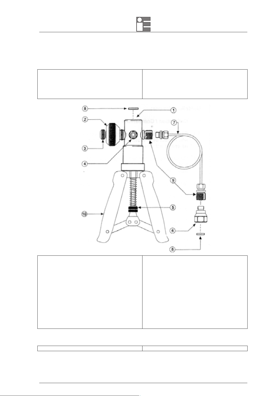
1. Connettore pressione - 3/8” BSP femmina
parallelo per strumento master (p.es. indicatore
digitale o analogico)
2. Valvola di regolazione fine
3. Valvola di rilascio pressione
4. Selettore pressione/vuoto
5. Protezione da sovrapressione per variare la
pressione massima in uscita
6. adattatore BSP o NPT
7. Tubo flessibile verso lo strumento sotto test
8. Guarnizione in nylon per adattatori BSP (vedi kit
guarnizioni fornito). NON usare nastro isolante
PTFE
9. Connettori zigrinati “quick-fit”
10. Impugnatura pompa
1. Pressure port – 3/8” BSP parallel female
connection to take master instruments e.g.
digital or analogue gauge)
2. Fine adjustment valve
3. pressure release valve
4. pressure / valve selector
5. adjustable stroke for varying maximum pressure
output (over pressure protection)
6. BSP or NPT adaptor set
7. Flexible hose to item under test
8. nylon seals for BSP adaptors (see seal kit
provided) DO NOT use PTFE tape for sealing
with parallel threads
9. knurled “quick-fit” connectors
10. pump handles
2.1 Tubi / adattatori – Hose / adaptors
I tubetti (7) e gli adattatori (6) si inseriscono The hoses (7) and adaptors (6) are fitted by simple

Instruction Manual MM850492 ed.1
6
semplicemente avvitandoli dentro i connettori (9)
girando interamente il dado zigrinato sul connettore
in senso antiorario.
screwing the into the connectors (9) by tuning the
knurled knut on the connector fully anti-clockwise
2.2 Valvola di rilascio (3) / Release valve (3)
Può essere usato per ridurre o rilasciare la pressione
nel sistema. L’ordine di pressione rilasciata è
dipendente dal grado di rotazione applicato agendo
sulla valvola. Una minima forza è necessaria per
chiudere il sistema.
This can be used to reduce or release the pressure
in the system. The rate of pressure reduction is
dependent upon the degree of rotation when opening
the valve. Minimal force is required to seal the
system.
2.3 Controllo di volume (2) / Volume control (2)
La pressione generata può essere finemente
regolata ruotando la valvola di regolazione fine (2) in
senso orario o antiorario per incrementare o
decrementare di conseguenza la pressione.
The pressure generated can be finely adjusted by
tuning the fine adjustment valve (2) either clockwise
or anticlockwise to increase or decrease pressure
accordingly
IMPORTANTE
IN NESSUN CASO RUOTARE LA VALVOLA DI REGOLAZIONE
FINE (2) OLTRE LA LINEA ROSSA IMPRESSA SULLA VITE.
SE CIÒ DOVESSE SUCCEDERE,LA PRESSIONE DEVE
ESSERE RILASCIATA DAL SISTEMA PRIMA DI TENTARE DI
AGIRE NUOVAMENTE SULLA VALVOLA DI REGOLAZIONE
FINE.
IMPORTANT
UNDER NO CIRCUMSTANCES SHOULD THE FINE
ADJUSTMENT VALVE (2) BE WOUND BACK BEYOND THE
RED LINE INDICATOR ON THE BODY.SHOULD THIS OCCUR,
THEN PRESSURE MUST BE RELEASED FROM THE SYSTEM
BEFORE ATTEMPTING TO RE-ENGAGE THE FINE
ADJUSTMENT VALVE.
2.4 Protezione da sovrapressioni (5) / Over pressure protection (5)
Per regolare il massimo output di pressione del
sistema, ruotare il dado (5) per aumentare o
decrementare la lunghezza del pistone.
To adjust the maximum output pressure of the
system turn the nuts (5) to increase or decrease the
stroke length
2.5 Selettore pressione / vuoto (4) – Pressure / vacuum selection (4)
Premere il selettore (4) per selezionare la modalità
desiderata. Assicurarsi che la valvola di rilascio (3)
sia aperta prima di cambiare modalità.
Press the selector (4) as indicated on the label to
engage the desired mode. Ensure that the release
valve (3) is open before changing mode.
Linea rossa / red line
Instruction Manual MM850492 ed.1
7
3 UTILIZZO / USE
ATTENZIONE
NON COLLEGARE LA POMPA A SORGENTI ESTERNE DI
PRESSIONE
ATTENTION
DO NOT CONNECT THE PUMP TO EXTERNAL PRESSURE
SOURCE
3.1 Calibrazione / confronto con misuratore analogico – Calibration /
Comparison against analogue gauge
•Sistemare il misuratore di riferimento sulla parte
alta del sistema (1).
NOTA: IL DADO DI RITENUTA DEVE ESSERE INTERAMENTE
AVVITATO,MA NON RICHIEDE DI ESSERE ECCESSIVAMENTE
STRETTO,POICHÉ LA TENUTA È ASSICURATA DALL’O-RING
•Connettere il dispositivo sotto test usando
l’opportuno adattatore e guarnizione (6) sulla fine
del tubetto flessibile (7) o direttamente sul corpo.
NOTA: GLI ADATTATORI SONO STRETTI AD UN MOMENTO
MASSIMO DI 15Nm
•Avvitare la valvola di regolazione fine (2)
interamente in senso orario
•Avvitare la valvola di regolazione fine (2) di 4-6
giri in senso antiorario
•Avvitare la valvola di rilascio di pressione (3)
interamente in senso orario, stringere per
assicurare una buona tenuta
•Agire sull’impugnatura (10) finche la pressione è
vicina a quella desiderata. Assicurarsi che
l’impugnatura siano pienamente strette fra di loro
ad ogni movimento, così da raggiungere la
massima pressione in uscita.
•Ruotare la valvola di regolazione fine (2) in senso
orario per incrementare la pressione o antiorario
per decrementarla, finché è raggiunta la
pressione richiesta.
NOTA: LA PRESSIONE PUÒ OSCILLARE PER CIRCA 30
SEC.DOPO CHE È STATA AUMENTATA A CAUSA DI EFFETTI
TERMODINAMICI,AGGIUSTAMENTO DELLE GUARNIZIONI O
ESPANSIONE DEL TUBETTO FLESSIBILE.
ATTENZIONE
NON AVVITARE MAI LA VALVOLA DI REGOLAZIONE FINE (2)
OLTRE LA LINEA ROSSA.
•Riduzioni sulla pressione possono inoltre essere
raggiunte agendo con cautela sulla valvola di
rilascio della pressione (3)
•Il vuoto è raggiunto usando la procedura vista
sopra dopo aver premuto completamente la
valvola di conversione verso la posizione di
•Fit a test gauge to the top of the test system (1).
NOTE: THE RETAINING NUT SHOULD BE SCREWED FULLY
DOWN BUT NEEDS TO BE NO MORE THAN FINGER TIGHT AS
SEAL IS ACHIEVED BY O-RING
•Connect item under test using appropriate adaptor
and sealing (6) at the end of the flexible hose (7)
or directly to body
NOTE:ADAPTORS TIGHTENED TO A MAXIMUM TORQUE OF
15NM
•Screw fine adjustment valve (2) fully clockwise
•Screw fine adjustment valve (2) 4-6 full turns
anticlockwise
•Screw pressure release valve (3) fully clockwise,
tightening to ensure good seal
•Operate handles (10) until the pressure is close to
that finally required. Ensure handles are fully
squeezed together on each stroke to achieve
maximum pressure output.
•Wind the fine adjustment (2) clockwise to increase
pressure or anticlockwise to decrease pressure
until required pressure is reached.
NOTE:THE PRESSURE MAY SETTLE FOR UP TO 30
SECONDS AFTER INCREASING PRESSURE DUE TO
THERMODYNAMIC EFFECTS,SETTLING OF SEALS AND
EXPANSION OF THE FLEXIBLE HOSE.
CAUTION
NEVER SCREW THE FINE ADJUSTMENT VALVE (2)
BEYOND THE RED LINE INDICATOR.
•Reductions in pressure can also be achieved by
careful use of the pressure release valve (3).
•Vacuum is achieved using the above procedure
and having the changeover valve (4) pushed
completely towards the vacuum position.
NOTE:RELEASE PRESSURE BEFORE CHANGING MODE.

Instruction Manual MM850492 ed.1
8
vuoto.
NOTA: RILASCIARE LA PRESSIONE PRIMA DI CAMBIARE
MODALITÀ
3.2 Uso con calibratori di pressione ad alta risoluzione / Use with high
resolution pressure calibrators
Quando la pompa è usata in abbinamento ad un
calibratore di pressione, le connessioni e l’uso sono i
medesimi di quelli visti nel caso precedente, tuttavia,
la più alta risoluzione ottenibile amplificherà la
visibilità degli effetti termodinamici. Questi effetti si
stabilizzeranno dopo circa 1min dalla
pressurizzazione.
NOTA: PER RISOLUZIONI MOLTO ALTE,COME 1mbar O
0.1In DI COLONNA D’ACQUA,PICCOLI MOVIMENTI DEL
TUBO DI RACCORDO (7) POSSONO TRADURSI IN
CONSIDEREVOLI CAMBIAMENTI DI PRESSIONE.
When used with instruments such as the PC6
Calibrator the connections and use are as for gauges
above, however the higher resolution available will
amplify the visibility of the thermodynamic effects as
above mentioned. These will settle to useable values
within one minute of pressurisation.
NOTE:ON VERY HIGH RESOLUTIONS SUCH AS 1MBAR OR
0.1 INCHES OF WATER,SMALL MOVEMENTS OF THE PIPE
MAY RESULT IN NOTICEABLE PRESSURE CHANGES.
3.3 Problemi di utilizzo / Fault investigation
Nel caso in cui il sistema sembri perdere pressione,
allora la procedura vista sopra deve essere ripetuta
assicurandosi di usare nuove guarnizioni, che gli
adattatori siano sufficientemente stretti e la valvola di
rilascio della pressione (3) sia saldamente chiusa.
NOTA: LE CONNESSIONI SUL SISTEMA TEST PORTATILE
SONO SIGILLATE CON O-RING O GUARNIZIONI E NON
DOVREBBERO PERDERE.
La connessione della tubatura verso il corpo può
essere verificata ma deve essere stretta a non più di
2 Nm
Non tentare di stringere gli altri apparecchi al sistema
di test poiché ciò potrebbe portare al
danneggiamento delle giunzioni a tenuta.
Quando si cercano delle perdite, si può notare che
dell’aria è risucchiata o espulsa dalla valvola di
conversione. Questo è normale e non deve
procurare preoccupazione.
In the event that the system appears to lose pressure
then the procedure above should be repeated
ensuring new seals are used, adaptors are tightened
su0ciently and the pressure release valve (3) is
tightened firmly.
NOTE:THE CONNECTIONS TO THE HAND HELD TEST
SYSTEM ARE SEALED WITH 'O'RING OR BONDED SEALS
AND SHOULD NOT LEAK.
The pipe to body connection can be checked but
tightened no more than 2 Nm.
DO NOT attempt to tighten the other fittings to the
test system as this could lead to damage of sealed
joints. When testing for leaks it may be noticed that
air is drawn in or expelled from around the
changeover valve. This is normal and should cause
no concern.

Instruction Manual MM850492 ed.1
9
4 MANUTENZIONE / MAINTENANCE
Il sistema dovrebbe essere utilizzato per
pressurizzare piccoli volumi, a causa delle ridotte
dimensioni.
Se non si utilizza il sistema per un certo periodo di
tempo, potrebbe essere difficile operare.
Il cilindro è stato leggermente ingrassato in fase di
assemblaggio ma, se dovesse essere necessaria
ulteriore lubrificazione, applicare una piccola quantità
di lubrificante nella parte interna del cilindro:
accedervi attraverso le 3 viti di fissaggio situate sotto
il collare nero.
The system should only be used for pressuring small
volumes due to its small displacement.
If the system has not been used for a period of time,
it could be difficult to operate on the first stroke.
The cylinder has been lightly greased on assembly
but, if additional lubrication should ever be required,
then apply a minimal amount to the inside of the
cylinder.
Access is via the three retaining screws located
under the black collar.
4.1 Termini di Garanzia / Warranty terms
Ogni strumento viene spedito con un certificato di
garanzia che indica la condizione di validità della
stessa.
Eurotron garantisce il prodotto verso difetti di
materiale o di lavorazione per un periodo di un anno
dalla data di acquisto.
Ogni uso non corretto, abuso, oppure modifiche e
riparazioni non autorizzate, annulleranno la
garanzia. Qualora fosse scoperto un difetto,
Eurotron riparerà o sostituirà lo strumento durante il
periodo di garanzia, escluse le spese di trasporto.
Questa garanzia si applica solo al compratore
originario. Si prega pertanto di includere una copia
della fattura originale, oppure dovrà essere applicata
una tariffa di servizio.
Prima di spedire il prodotto, contattate la Eurotron
per ottenere un numero di autorizzazione ed
istruzioni di spedizione.
Eurotron Instruments warrants its products against
defects in materials and workmanship.
If the unit should malfunction, it must be returned
during the warranty period, transportation prepaid, to
Eurotron for evaluation. Upon examination, if the
unit is found to be defective it will be repaired or
replaced at no charge.
Eurotron‘s WARRANTY does not apply to defects
resulting from any action of the purchaser, including
but not limited to mishandling, improper interfacing,
operation outside of design limits, improper repair, or
unauthorized modification. This WARRANTY is VOID
if the unit shows evidence of having been tampered
with or shows evidence of being damaged as a result
of excessive corrosion; or current, heat, moisture or
vibration; improper specification; misapplication;
misuse or other operating conditions outside of
Eurotron‘s control.
This warranty applies to the original purchaser only.
Please include a copy of the original invoice or a
small service charge may be applied.
Direct all warranty and repair requests/inquiries to
the Eurotron Customer Service Department. Before
returning any product(s) to eurotron, purchaser must
obtain an authorized return (ar) number from
eurotron‘s customer service department (in order to
avoid processing delays).
The purchaser is responsible for shipping charges,
freight, insurance and proper packaging to prevent
breakage in transit.
Table of contents
Popular Portable Generator manuals by other brands

Grupel
Grupel GR3000 Operator's manual

VITO
VITO PRO-POWER VIGI1250 instruction manual

Mecc Alte spa
Mecc Alte spa EC Series Operating and maintenance instructions

EUROM
EUROM Independ-2500 instruction manual

Generac Portable Products
Generac Portable Products 4000EXL owner's manual

jcb
jcb G70RS quick start guide


Venmar
Venmar 550VF1 Installation and user guide

Lincoln Electric
Lincoln Electric COOL ARC 25 Operator's manual

Seto
Seto EP1000 Instructions for use

SSI
SSI MPG-2 instruction sheet

Generac Power Systems
Generac Power Systems 7500EXL Rated watt Extended Life Generator Operator's manual

Generac Power Systems
Generac Power Systems CENTURION 006104-1 owner's manual