EURUSBLOWER ZZ2MDSL User manual
-----------------------------------------------------------------------------------------------------------------------------------------------
Eurus Blower, Inc. http://www.eurusblower.com E-mail: sales@eurusblower.com Pg. 1
All rights reserved. No part of this manual may be reproduced in any form by any
means without permission from Eurus Blower, Inc.
Please read this service manual carefully before installation and operation.
Rotary Blower Service Manual
Models: ZZ2MDSL,ZZ3MDSL,ZZ4MDSL
ZZ5MDSL,ZZ6MDSL,ZZ7MDSL
ZZ2LDSL,ZZ3LDSL,ZZ4LDSL
ZZ5LDSL,ZZ6LDSL,ZZ7LDSL
04/2014

-----------------------------------------------------------------------------------------------------------------------------------------------
Eurus Blower, Inc. http://www.eurusblower.com E-mail: sales@eurusblower.com
Pg. 2
All rights reserved. No part of this manual may be reproduced in any form by any
means without permission from Eurus Blower, Inc.
Table of Contents
1. SUMMARY .......................................................................................................................................................4
2. FOREWORD.....................................................................................................................................................4
3. SAFETY PRECAUTIONS ...............................................................................................................................5
4. TECHNICAL SPECIFICATIONS ..................................................................................................................6
4.1.
R
OTARY
B
LOWER
S
PECIFICATIONS
.................................................................................................... 6
4.2.
A
MBIENT
T
EMPERATURES
.................................................................................................................. 8
4.3.
M
AXIMUM
A
LLOWABLE
O
VERHUNG
L
OAD
(OHL) ........................................................................... 8
4.4.
O
IL
C
APACITIES
.................................................................................................................................. 9
4.5.
R
ECOMMENDED
L
UBRICANT
............................................................................................................ 10
4.6.
N
AMEPLATE
....................................................................................................................................... 10
4.7.
D
IMENSIONAL
D
RAWINGS
................................................................................................................. 11
4.8.
P
ERFORMANCE
C
URVES
.................................................................................................................... 11
4.9.
P
ERFORMANCE
T
ABLES
.................................................................................................................... 11
5. SAFETY INSTRUCTIONS............................................................................................................................11
5.1.
W
ARNING
S
YMBOLS
.......................................................................................................................... 11
5.2
S
AFETY WARNING AND REGULATIONS
(OSHA
CFR
29,
19100)........................................................ 12
5.3
G
ENERAL
R
EFERENCES
...................................................................................................................... 13
6. ARRIVAL AND USE OF THE ROTARY BLOWER...................................................................................13
6.1
A
RRIVAL
I
NSPECTION
......................................................................................................................... 13
6.2
P
ROPER
U
SE OF THE
R
OTARY
B
LOWER
............................................................................................. 14
7. MOVING AND HANDLING .........................................................................................................................14
7.1
H
ANDLING
I
NSTRUCTIONS
................................................................................................................. 14
7.2
H
ANDLING WITH A
F
ORKLIFT OR
P
ALLET
J
ACK
............................................................................... 14
7.3
H
ANDLING WITH A
C
RANE
H
OOK
...................................................................................................... 15
7.4.
S
TORAGE
............................................................................................................................................ 15
7.4.1 Temporary Storage....................................................................................................................... 15
7.4.2. Storage for longer than one year ................................................................................................ 15
7.4.3. Recommended Oils for Storage................................................................................................... 15
7.4.4. Operating after long-term storage.............................................................................................. 16
8. OPERATIONAL CHARACTERISTICS AND CONSTRUCTION ...........................................................16
8.1
O
PERATIONAL
C
HARACTERISTICS
.................................................................................................... 16
8.2
C
ONSTRUCTION
.................................................................................................................................. 17
8.3
H
ORIZONTAL
F
LOW
C
ONFIGURATION
............................................................................................... 18
8.4
V
ERTICAL
F
LOW
C
ONFIGURATION
.................................................................................................... 18
8.5
S
HAFT
D
IAMETER AND
O
IL
D
RAIN
(O
IL
F
ILL
)
P
LUG
T
HREAD
......................................................... 19
9. INSTALLATION AND DESIGN REQUIREMENTS .................................................................................19
9.1.
I
NSTALLATION
R
EQUIREMENTS
........................................................................................................ 19
9.2
MOUNTING
CONFIGURATIONS................................................................................................. 20

-----------------------------------------------------------------------------------------------------------------------------------------------
Eurus Blower, Inc. http://www.eurusblower.com E-mail: sales@eurusblower.com Pg. 3
All rights reserved. No part of this manual may be reproduced in any form by any
means without permission from Eurus Blower, Inc.
9.3.
D
RIVE
M
OTOR
................................................................................................................................... 21
9.3.1. Direct coupled drive with flexible coupling ................................................................................ 22
9.3.2. V-belt drive.................................................................................................................................. 22
9.4.
S
YSTEM
S
AFETY
E
QUIPMENT
........................................................................................................... 23
9.4.1. Safety relief valve........................................................................................................................ 23
9.4.2 Check valve.................................................................................................................................. 24
9.4.3 Visual Indicators of Temperature and Pressure ........................................................................... 25
9.4.4 Monitoring Device switches......................................................................................................... 25
9.4.5. Noise reduction ........................................................................................................................... 25
10. OPERATING A ROTARY BLOWER.........................................................................................................26
10.1.
P
RIOR TO
S
TARTING
U
NIT FOR
F
IRST
T
IME
................................................................................... 26
10.2.
S
TARTING AND
S
TOPPING THE
R
OTARY
B
LOWER
.......................................................................... 28
10.3.
T
ROUBLE SHOOTING
....................................................................................................................... 28
10.3.1 Trouble Shooting Guide ............................................................................................................. 29
11. MAINTENANCE ..........................................................................................................................................30
11.1
R
ULES FOR MAINTENANCE
............................................................................................................... 30
11.2.
R
EGULAR
M
AINTENANCE
S
CHEDULE
............................................................................................. 30
11.3
O
IL LEVEL CHECK
............................................................................................................................. 31
11.4
L
UBRICATING OIL
C
HANGE
.............................................................................................................. 32
12. SPARE PARTS AND AFTER SALES .........................................................................................................33
13. MAINTENANCE SCHEDULE SHEET .....................................................................................................51
-----------------------------------------------------------------------------------------------------------------------------------------------
Eurus Blower, Inc. http://www.eurusblower.com E-mail: sales@eurusblower.com
Pg. 4
All rights reserved. No part of this manual may be reproduced in any form by any
means without permission from Eurus Blower, Inc.
1. SUMMARY
Before any installation or operation, read this Service Manual carefully. Check the
package for damage. If blower is damaged file a claim with the carrier and notify EURUS.
Use care when operating the rotary blowers, see Safety Instructions Make sure both drive
and driven equipment is correctly lubricated prior to start-up, see Oil Capacities and
Recommended Lubricant.
In the event of trouble during installation or operation, do not attempt repairs of blower.
Notify Eurus, giving all nameplate information and you will receive technical service. See
Operating a Rotary Blower
Before installing the blower, See Installation and Design Requirements.Store the rotary blower
in a dry, covered space, see Storage.Always operate rotary blowers in a dry and dust free
environment, SeeOperational Characteristics and Construction.
2. FOREWORD
ZZDSL Series blowers are the product of advanced global engineering and
manufacturing. To receive maximum service and performance from this machine, the
owner is advised to exercise extreme care in its operation and maintenance. This
manual is written to give all operation and maintenance personnel essential information
for day-to-day operation, maintenance and adjustment. The use of these instructions
will result in economical operation and downtime.
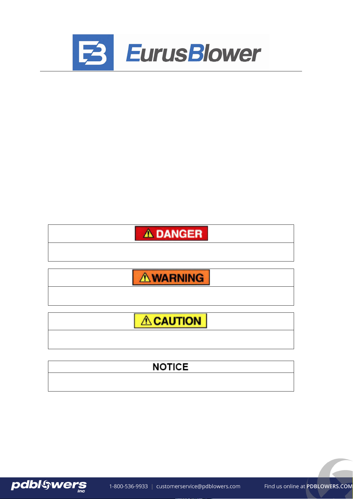
Danger is used to indicate the presence of a hazard which will cause
severe personal injury, death, or substantial damage if ignored.
Warning is used to indicate the presence of a hazard which can cause
severe personal injury, death, or substantial damage if ignored.
Caution is used to indicate the presence of a hazard which will or can
cause minor personal injury or property damage if ignored.
Notices are used to notify all concerned of any installation, operation or
maintenance information which is important but not hazard-related.
-----------------------------------------------------------------------------------------------------------------------------------------------
Eurus Blower, Inc. http://www.eurusblower.com E-mail: sales@eurusblower.com Pg. 5
All rights reserved. No part of this manual may be reproduced in any form by any
means without permission from Eurus Blower, Inc.
3. SAFETY PRECAUTIONS
Safety is everyone’s concern and is based on the use of good common sense.
Situations or circumstances cannot be predicated or covered by established
rules .Therefore, use past experience , watch out for safety hazards and be
cautious .Some general safety precautions are given below.
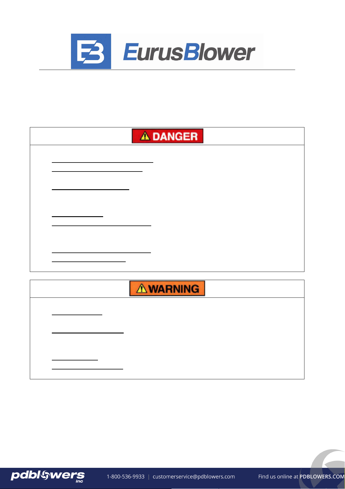
Failure to observe these notices may result in injury to or death of personnel
zKeep fingers and clothing away form revolving fan, drive coupling, etc.
zDo not use the air discharge from this unit for breathing… it is not suitable
for human consumption.
zDo not loose or remove the oil filler plug ,drain plugs, covers or break any
connections ,etc., in the blower air or oil system until the until the is shut
down and the air pressure has been relieved.
zElectrical shock can and may be fatal.
zBlower unit must be grounded in accordance with the National Electrical
Code .A ground jumper equal to the size of the equipment ground conductor
must be used to connect the blower motor base to the unit base.
zOpen main disconnect switch, tag and lockout before working on the control.
zDisconnect the blower from its power source, tag and lockout before working
on the control.
Failure to observe these notices could result in damage to equipment
zStop the blower if any repairs or adjustments on or around the blower are
required.
zDisconnect the blower from its power source, tag and lockout before working
on the unit-this machine maybe automatically controlled and may start at any
time.
zDo not exceed the rated maximum speed shown on the nameplate
zDo not operate blower if safety devices are not operating properly. Check
periodically. Never bypass safety devices.
-----------------------------------------------------------------------------------------------------------------------------------------------
Eurus Blower, Inc. http://www.eurusblower.com E-mail: sales@eurusblower.com
Pg. 6
All rights reserved. No part of this manual may be reproduced in any form by any
means without permission from Eurus Blower, Inc.
4. Technical Specifications
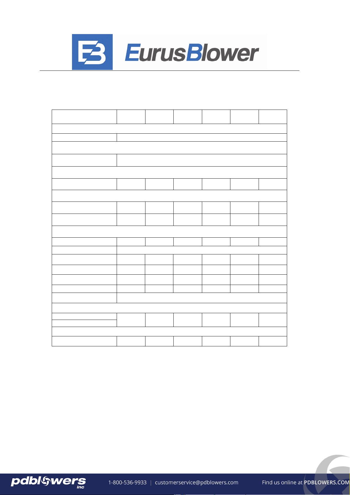
4.1. Rotary Blower Specifications
ZZ2M
DSL
ZZ3M
DSL
ZZ4M
DSL
ZZ5M
DSL
ZZ6M
DSL
ZZ7M
DSL
Configuration 1
Vertical or Horizontal Flow Configuration
Direction of Rotation 1
CW or CCW
Inlet CFM
2, 5 (@maximum speed and maximum ∆p)
73 159 346 481 751 1316
Power Consumption 3, 5
(BHP @ maximum speed and maximum ∆p)
Blower 6.2
(12 psi)
12.2
(12 psi)
19.8
(10 psi)
35.7
(13 psi)
59.8
(14 psi)
70.9
(10 psi)
Vacuum 3.8
(15 InHg)
7.5
(15 InHg)
15.7
(16 InHg)
21.6
(16 InHg)
35.3
(16 InHg)
56.8
(16 InHg)
Operating Limits
Max RPM
5275 3600 3600 2850 2350 2050
Max Case Pressure, 25 (psig)
Max ∆p Blower
4,5
(psi)
12 12 10 13 14 10
Max ∆p Vacuum
4,5
(InHg)
15 15 16 16 16 16
Max Pressure Ratio
4
2:1 2:1 2.15:1 2.15:1 2.15:1 2.15:1
Max Discharge Temp. ℉
313 287 290 285 308 288
Max Inlet Temp. ℉ 104
Connection
Inlet Port (ANSI)
Discharge Port (ANSI) NPT 1” NPT 2” NPT 2.5” NPT 4” 5” 6”
Weight
(lb)
48 88 132 217 364 684

-----------------------------------------------------------------------------------------------------------------------------------------------
Eurus Blower, Inc. http://www.eurusblower.com E-mail: sales@eurusblower.com Pg. 7
All rights reserved. No part of this manual may be reproduced in any form by any
means without permission from Eurus Blower, Inc.
ZZ2L
DSL
ZZ3L
DSL
ZZ4L
DSL
ZZ5L
DSL
ZZ6L
DSL
ZZ7L
DSL
Configuration 1
Vertical or Horizontal Flow Configuration
Direction of Rotation 1
CW or CCW
Inlet CFM
2, 5 (@maximum speed and maximum ∆p)
176 311 527 862 1521 2242
Power Consumption 3, 5
(BHP @ maximum speed and maximum ∆p)
Blower 7.1
(7 psi)
12.5
(7 psi)
20.4
(7 psi)
32.3
(7 psi)
58.7
(7 psi)
72.7
(7 psi)
Vacuum 7
(14 InHg)
12.2
(14 InHg)
20
(14 InHg)
31.6
(14 InHg)
57.8
(14 InHg)
12.2
(14 InHg)
Operating Limits
Max RPM
5275 3600 3600 2850 2350 2050
Max Case Pressure, 25 (psig)
Max ∆p Blower
4,5
(psi)
7 7 7 7 7 7
Max ∆p Vacuum
4,5
(InHg)
12 14 14 14 14 14
Max Pressure Ratio
4
1.88:1 1.88:1 1.88:1 1.88:1 1.88:1 1.88:1
Max Discharge Temp. ℉
238 248 239 239 248 198
Max Inlet Temp. ℉ 104
Connection
Inlet Port (ANSI)
Discharge Port (ANSI) NPT 2” NPT 2.5” NPT 3” NPT 4” 6” 8”
Weight
(lb)
60 111 162 285 529 838
Notes:
1. The user can select the configuration according to their installation requirements.
2. The effective volume flow is dependent on the speed and the differential pressure.
3. The power consumption is dependent upon the operating point required, e.g. volume-flow
and differential pressure.
4. The ratings based on inlet air at standard pressure of 14.7 psia, standard temperature of 68
degrees F, and specific gravity of 1.0.
5. ∆p = discharge pressure – inlet pressure

-----------------------------------------------------------------------------------------------------------------------------------------------
Eurus Blower, Inc. http://www.eurusblower.com E-mail: sales@eurusblower.com
Pg. 8
All rights reserved. No part of this manual may be reproduced in any form by any
means without permission from Eurus Blower, Inc.
4.2. Ambient Temperatures
Minimum ambient temperature *………........................................................ 5 °F
Maximum ambient temperature *…………………………………. .............. 104 °F
* These temperature limits are based on lubricants specified here within. Consult Eurus
Blower for recommendations if operating environment temperatures exceed limits (see
lubricant recommendations, section 4.5).
4.3. Maximum Allowable Overhung Load (OHL)
ARC OF CONTACT FACTORS
Dimensions
(Inches)
MODEL
Gear
Diameter
(Inches) A B C
Maximum
Allowable
Moment(LB-IN)
ZZ2M(L)DSL 2.76 2.78 0.87 0.25 150
ZZ3M(L)DSL 3.54 2.90 0.94 0.25 390
ZZ4M(L)DSL 4.04 3.63 1.26 0.3 500
ZZ5M(L)DSL 5.08 4.09 1.57 0.3 1280
ZZ6M(L)DSL 5.98 4.51 1.57 0.38 1800
ZZ7M(L)DSL 7.09 4.95 1.68 0.38 3000
Z Ac Z Ac Z Ac Z Ac Z Ac Z Ac
0.000 1.000 0.250 0.966 0.500 0.926 0.750 0.879 1.000 0.823 1.250 0.751
0.025 0.997 0.275 0.962 0.525 0.922 0.775 0.874 1.025 0.816 1.275 0.742
0.050 0.994 0.300 0.958 0.550 0.917 0.800 0.869 1.050 0.810 1.300 0.734
0.075 0.990 0.325 0.954 0.575 0.913 0.825 0.864 1.075 0.803 1.325 0.725
0.100 0.987 0.350 0.951 0.600 0.908 0.850 0.858 1.100 0.796 1.350 0.716
0.125 0.983 0.375 0.947 0.625 0.904 0.875 0.852 1.125 0.789 1.375 0.706
0.150 0.980 0.400 0.943 0.650 0.899 0.900 0.847 1.150 0.782 1.400 0.697
0.175 0.977 0.425 0.939 0.675 0.894 0.925 0.841 1.175 0.774 1.425 0.687
0.200 0.973 0.450 0.935 0.700 0.889 0.950 0.835 1.200 0.767
0.225 0.969 0.475 0.930 0.725 0.884 0.975 0.829 1.225 0.759
-----------------------------------------------------------------------------------------------------------------------------------------------
Eurus Blower, Inc. http://www.eurusblower.com E-mail: sales@eurusblower.com Pg. 9
All rights reserved. No part of this manual may be reproduced in any form by any
means without permission from Eurus Blower, Inc.
CALCULATION OF BELT PULL
CALCULATION OF SHAFT MOMENT
4.4. Oil Capacities
At the drive end, the bearings are lubricated by the slinger, which must be on the lowest rotor
when in a vertical configuration.
At the gear end, the timing gear teeth are lubricated by being partially submerged in oil. The
gear teeth serve as oil slingers for gear end bearings.
Belt Pull = ⎥
⎦
⎤
⎢
⎣
⎡−
AC
AC5.2 ×⎥
⎦
⎤
⎢
⎣
⎡
×
××
RPMD
FSHp ..125954
Key:
Ac = Arc of Contact Factor (Refer to Arc of Contact Factor Chart above)
Hp = Blower Horsepower for Operating Conditions
S.F. = Actual Drive Service Factor
D = Blower Sheave Pitch Diameter in Inches
RPM = Blower Sheave Speed
Z = ⎥
⎦
⎤
⎢
⎣
⎡
(in)DistanceCenterSheave
(in)DiameterPitchSheaveSmall-(in)DiameterPitchSheaveLarge
Shaft Moment (LB-IN) = Belt Pull ⎥
⎦
⎤
⎢
⎣
⎡⎟
⎠
⎞
⎜
⎝
⎛
++×
2
WidthSheave
CB
Horizontal Flow Configuration Vertical Flow Configuration
Model Gear
Diameter(in) Gear End Drive End Gear End Drive End
ZZ2M(L)DSL 2.76 0.11PT (1.83 OZ) 0.009PT(0.15 OZ) 0.27PT(4.59 OZ) 0.016 PT (0.27 OZ)
ZZ3M(L)DSL 3.54 0.23 PT (4.03 OZ) 0.1 PT (1.8 OZ) 0.66 PT (11.44 OZ) 0.26 PT (4.56 OZ)
ZZ4M(L)DSL 4.04 0.39 PT(6.70 OZ) 0.13PT( 2.23 OZ) 0.88 PT (15.15 OZ) 0.35 PT (5.97 OZ)
ZZ5M(L)DSL 5.08 0.86 PT (14.83 OZ) 0.41 PT (7.15 OZ) 2.11 PT (36.41 OZ) 0.97 PT (16.67 OZ)
ZZ6M(L)DSL 5.98 1.64PT(28.21 OZ) 0.63PT(10.81 OZ) 3.38 PT (58.24 OZ) 1.22 PT (20.97 OZ)
ZZ7M(L)DSL 7.09 4PT(68.86 OZ) 1.26 PT (21.67 OZ) 6.65 PT (114.67 OZ) 2.36 PT (40.72 OZ)

-----------------------------------------------------------------------------------------------------------------------------------------------
Eurus Blower, Inc. http://www.eurusblower.com E-mail: sales@eurusblower.com
Pg. 10
All rights reserved. No part of this manual may be reproduced in any form by any
means without permission from Eurus Blower, Inc.
4.5. Recommended Lubricant
Use the appropriate grade and viscosity of industrial type, non-detergent, rust inhibiting,
anti-foaming oil (Reference Chart 1 below). The correct oil depends on the range of
ambient temperatures as well as the range of discharge temperatures.
Synthetic lubricants are highly recommended over mineral lubricants: synthetics last up to 4 times
longer; and a single viscosity can cover a broader temperature range.
Consult factory for oil recommendations on special applications.
4.6. Nameplate
The nameplate of the rotary blower is located on the oil cover gear side

-----------------------------------------------------------------------------------------------------------------------------------------------
Eurus Blower, Inc. http://www.eurusblower.com E-mail: sales@eurusblower.com Pg. 11
All rights reserved. No part of this manual may be reproduced in any form by any
means without permission from Eurus Blower, Inc.
4.7. Dimensional Drawings
Documents can be provided by Eurus Blower Customer Service Department
4.8. Performance Curves
Performance curves can be provided by Eurus Blower Customer Service Department
4.9. Performance Tables
Performance tables can be provided by Eurus Blower Customer Service Department
5. Safety Instructions
Read this service manual carefully and abide by all warnings and precautions before putting
the rotary blower into operation and/or before performing any maintenance.
5.1. Warning Symbols
Symbol Meaning
This symbol indicates information that can cause injury or
death. It is critical that these rules are observed and that
extreme care is taken in these cases. For their own
protection, inform all other users of these safety rules.
Observe general safety and accident prevention rules as well
as the safety procedures in this manual.
-----------------------------------------------------------------------------------------------------------------------------------------------
Eurus Blower, Inc. http://www.eurusblower.com E-mail: sales@eurusblower.com
Pg. 12
All rights reserved. No part of this manual may be reproduced in any form by any
means without permission from Eurus Blower, Inc.
This symbol indicates considerable attention must be paid to
recommendations, regulations, references and correct
sequencing so that damage and/or destruction of the rotary
blower and/or other equipment is prevented.
This symbol indicates environmental protection measures.
This symbol indicates manual operations that are to be
performed by the operator or service technician.
5.2 Safety warning and regulations (OSHA CFR 29, 19100)
Observe the following warnings when operating rotary
blowers:
zBecause of danger to maintenance and operation personnel from rotating
parts, high temperatures and harmful noise, protective measures against
these hazards must be taken by the user.
zNo open flame or flying sparks should be in the vicinity of unit.
zIf any welding or grinding work is needed near the rotary blower, ensure
that sparks or high temperatures cannot cause fire or explosion.
zOperating personnel must be instructed on the necessity of wearing
hearing protection during operation of the rotary blower - especially when
operating without the acoustic hood.
zDo not stay for long periods in the direct vicinity of operating rotary
blowers with damaging noise levels.

-----------------------------------------------------------------------------------------------------------------------------------------------
Eurus Blower, Inc. http://www.eurusblower.com E-mail: sales@eurusblower.com Pg. 13
All rights reserved. No part of this manual may be reproduced in any form by any
means without permission from Eurus Blower, Inc.
zDo not use rotary blowers to convey or handle explosive or damaging gases.
zBecause of the high temperatures generated (up to 313℉), do not touch
pipes or ancillaries during operation of the rotary blower. Wait until the
blower has cooled down and pressure is vented before performing any
repairs.
zOnly specially trained personnel should work on power driven systems.
5.3 General References
The rotary blower is not capable of functioning as an independent
machine: it is designed as a sub-component to be used and controlled
within a bigger system.
The rotary blower may only be put into operation as an integral part
of a complete system that has been subjected to a safety inspection
proving that it conforms to the requirements of relevant safety
regulations (see OSHA CFR 29, 1910)
6. Arrival and Use of the Rotary Blower
6.1 Arrival Inspection
Before accepting the shipment, perform the following
inspections:
zReview the packing slip and verify that all components and
accessories are included and undamaged. Uncrate or remove,
from packing, all items and inspect them thoroughly. Report
any damage or missing items described on the packing slip
with the carrier.
zRotate the shaft and insure smooth rotation by hand. If the
contamination covers are still on the inlet and outlet of the
unit, expect some resistance when turning the shaft..

-----------------------------------------------------------------------------------------------------------------------------------------------
Eurus Blower, Inc. http://www.eurusblower.com E-mail: sales@eurusblower.com
Pg. 14
All rights reserved. No part of this manual may be reproduced in any form by any
means without permission from Eurus Blower, Inc.
zDo not remove port covers. A rust inhibitor is applied at the factory to insure rust free air
chamber. Wait until installation before removing covers. Once removed, the air chamber
will be exposed to dirt and debris and the rust inhibitor will begin to evaporate.
6.2 Proper Use of the Rotary Blower
The rotary blower package is intended solely for the transport of oil-free air or any inert
gas without any liquids or solids and in conformity with the technical specifications.
For special gas applications contact Eurus Blower’s Engineering Department.
Do not use this blower for any combustible or oxidizing gas
applications.
Any other use is considered incorrect and will void the warranty and may cause injury or
death. The manufacturer cannot accept liability for any damage caused by incorrect use. The
user alone is liable for any risks incurred.
Correct use also means compliance with the installation, removal, commissioning,
operational and maintenance instructions written in this manual.
This service manual is intended for operating, maintenance and supervisory personnel
use only.
7. Moving and Handling
7.1 Handling Instructions
To avoid damage to the rotary blower, it is recommended to use a forklift truck; pallet
jack; hoist; crane; chain; cable or a sling with certified capacities according to safety.
Abide by all safety and regulatory procedures when handling rotary blowers.
7.2 Handling with a Forklift or Pallet Jack
Always place the rotary blower on a suitable pallet, box or platform to prevent tipping.
Be sure the platform can support the full weight of the unit. Directly fasten the rotary
Do not lift rotary blower unit directly with the forks of a forklift
or pallet jack: this can cause injury to operator and damage to the
unit.
-----------------------------------------------------------------------------------------------------------------------------------------------
Eurus Blower, Inc. http://www.eurusblower.com E-mail: sales@eurusblower.com Pg. 15
All rights reserved. No part of this manual may be reproduced in any form by any
means without permission from Eurus Blower, Inc.
blower to the structure using the mounting feet provided prior to moving the unit.
7.3 Handling with a Crane Hook
When lifting the rotary blower with a crane hook and slings, use the two Lifting Lugs
provided to distribute the load evenly.
•When transporting the rotary blower with a crane, all
standard safety practices and regulations regarding this
type of operation must be observed.
•Do not stand below a hanging load.
•Do not exceed the maximum permissible lifting weight
specified for the lifting device and rigging elements.
•Avoid sudden, sharp vertical movements when lifting,
lowering and transporting the rotary blower.
•Lift no higher than needed.
7.4. Storage
7.4.1 Temporary Storage
If the unit will need to be stored for a short period of time, or there is a long period of
time between delivery and installation, store the rotary blower in a dry, covered space.
Leave the flanged ports blanked off to prevent contamination of the internal surfaces.
Keep the unit off of the ground.
7.4.2. Storage for longer than one year
Use Temporary Storage 7.4.1 recommendations plus:
zApply rust inhibiting oil/grease onto the flanged ports, drive shaft, and any other
base metal to protect against corrosion.
zIsolate from secondary vibration
zChange oil annually.
Rotate shaft periodically (a few times biweekly is recommended)
7.4.3. Recommended Oils for Storage
External:
EXXON RUST BAN 326

-----------------------------------------------------------------------------------------------------------------------------------------------
Eurus Blower, Inc. http://www.eurusblower.com E-mail: sales@eurusblower.com
Pg. 16
All rights reserved. No part of this manual may be reproduced in any form by any
means without permission from Eurus Blower, Inc.
MOBIL Mobilarma 777 OR 778
SHELL V-Product 9703
Internal:
MOBIL Mobilarma 523 or 524
SHELL RIMULA 30 or ROTELLA T 20W20
7.4.4. Operating after long-term storage
To operate the unit after long-term storage, perform the following:
zMake sure the rotors rotate smoothly when rotated by hand; the lobe surface and the
air chamber inside are clear.
zPerform the standard measures for installing a new unit.
Change the lubricating oil.
8. Operational Characteristics and Construction
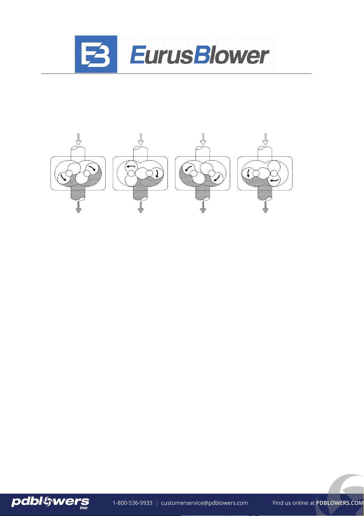
8.1 Operational Characteristics
To develop pressure and move air, two bi-lobe rotors, synchronized by a pair of timing
gears, rotate in opposite directions in two cylindrical bores within housing.
A defined quantity of air entering the inlet port is trapped between the rotor and the
housing and is carried over to the discharge port against the pressure from the application.
The pressure developed depends upon the resistance of the system as well as the inlet and
discharge pressures.
Each trapped volume occurs two times every revolution for each rotor, commonly referred
to as the volume flow per revolution. Multiplying this by the shaft speed will define the flow
rate entering the inlet port. Changing the rotational speed directly affects the volume flow.
Simultaneously, the synchronized rotors and housing serve to prevent back flow by the
close proximity of the rotors to one another and the proximity of the rotors to the housing.
Because there is no contact between the rotors and the case, there is no wear and no
lubrication is required. (Oil is required to lubricate the bearings and gear). The lack of contact
means that some leakage occurs and the rate is directly related to the pressure differential
between ports. As the pressure differential increases, the leakage rate increases.
-----------------------------------------------------------------------------------------------------------------------------------------------
Eurus Blower, Inc. http://www.eurusblower.com E-mail: sales@eurusblower.com Pg. 17
All rights reserved. No part of this manual may be reproduced in any form by any
means without permission from Eurus Blower, Inc.
Furthermore, as the leakage rate increases the adiabatic efficiency decreases, increasing the
discharge temperature and power requirement.
The net flow rate and efficiency is then dependent upon the shaft speed, volume flow per
revolution, and leakage rate at the operational pressure point.
8.2 Construction
As described in operating characteristics 8.1, each blower is constructed for a specific
volume flow rate per revolution and is defined by design and rotor length. The ZZDSL Series
offers (12) twelve models to choose from. Each model offers a variety of flow rates by
changing the rotational speed.
To maximize efficiency, materials and clearances are chosen to maintain minimal
clearance but reliable operation up to a limiting pressure differential, due to thermal overload.
Thermal overload is a point at which the blower cannot dissipate enough heat (thermal energy)
to maintain design clearances due to thermal expansion and deformation.
The drive shaft, located on only one rotor, can be driven in both directions and is suitable
for direct or belt driven. Directly coupling the motor to the driveshaft allows for maximum
power transmission.
The integrated feet allow for a universal installation: in both vertical and horizontal
configurations the blower can be mounted from any side, top or bottom.
-----------------------------------------------------------------------------------------------------------------------------------------------
Eurus Blower, Inc. http://www.eurusblower.com E-mail: sales@eurusblower.comPg. 18
All rights reserved. No part of this manual may be reproduced in any form by any
means without permission from Eurus Blower, Inc.
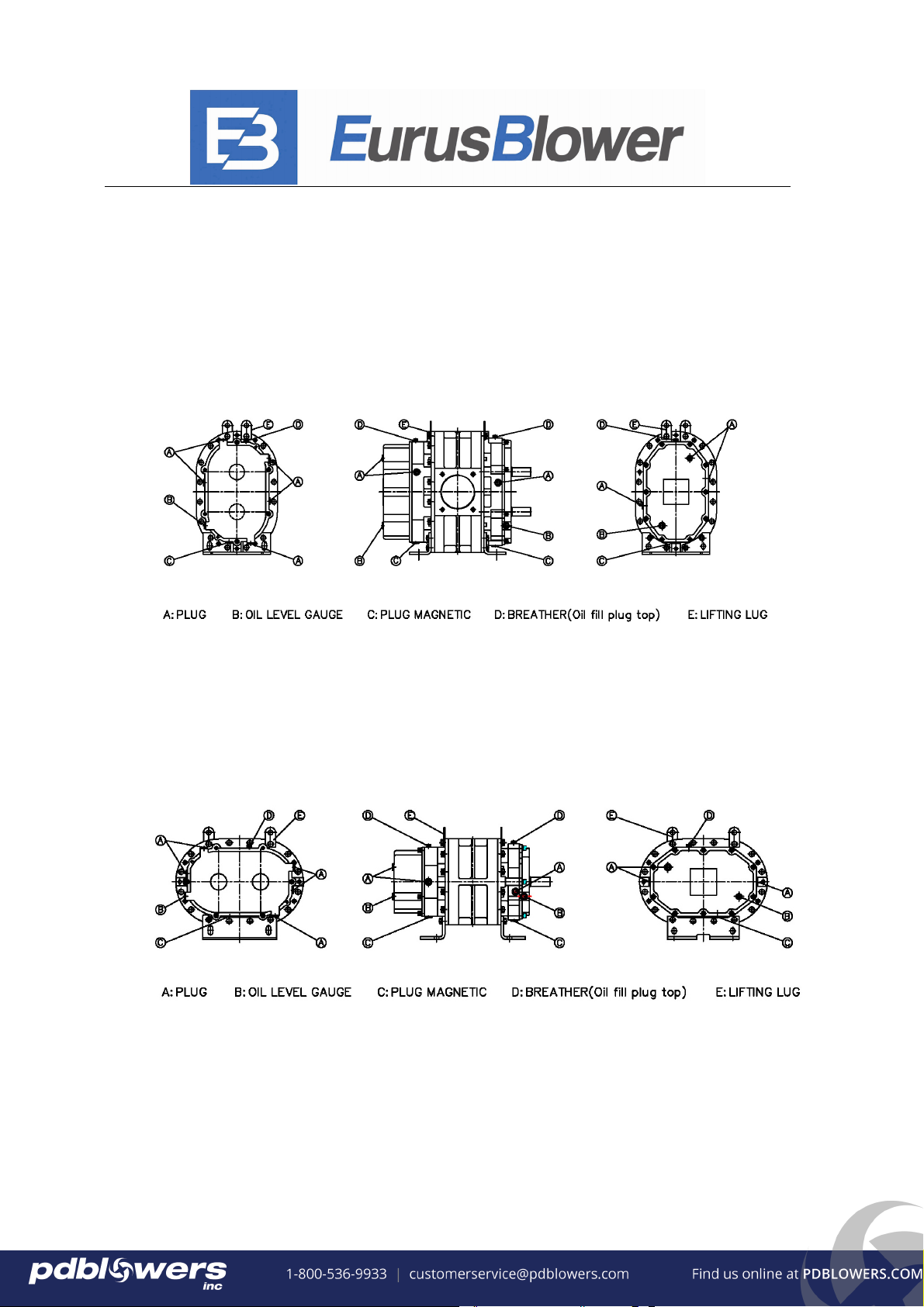
8.3 Horizontal Flow Configuration
• See the following diagram for the positions of the oil level gauge, breather,
Plugs, plug magnetic, lifting lug and mounting feet.
• See chapter 4.4 for oil capacities.
8.4 Vertical Flow Configuration
• See the following diagram for the positions of the oil level gauge, breather,
Plugs, plug magnetic, lifting lug and mounting feet.
• See chapter 4.4 for oil capacities.
-----------------------------------------------------------------------------------------------------------------------------------------------
Eurus Blower, Inc. http://www.eurusblower.com E-mail: sales@eurusblower.com Pg. 19
All rights reserved. No part of this manual may be reproduced in any form by any
means without permission from Eurus Blower, Inc.
8.5 Shaft Diameter and Oil Drain (Oil Fill) Plug Thread
Model
Dimension
ZZ2M(L)
DSL
ZZ3M(L)
DSL
ZZ4M(L)
DSL
ZZ5M(L)
DSL
ZZ6M(L)
DSL
ZZ7M(L)
DSL
Shaft Diameter 0.625 0.75 0.875 1.125 1.375 1.562
Oil Fill Plug Thread
Oil Drain Plug Thread
M12×1 M16×1.5 M20×1.5
We can use Adapter Substitute in order to change the oil fill plug and oil drain plug thread into inches.
9. Installation and Design Requirements
9.1. Installation Requirements
Always operate rotary blowers in a dry and dust free environment.
Most ZZDSL blowers are shipped from the factory in the vertical flow configuration.
According to installation requirements, a ZZDSL blower can be used in the vertical flow
configuration with the drive shaft on either the right or left side; or in the horizontal flow
configuration with the drive shaft in the top or bottom position. You must relocating the oil
level gauge, breather, Plugs, plug magnetic, lifting lugs and mounting feet to the proper
position. When changing the flow configuration, from vertical to horizontal or from
horizontal to vertical, the mounting feet must be removed and rotated 90° so the side that
was originally bolted to the blower becomes the base of the foot in the rotated position.
As shown in 8.3 and 8.4.
Mount the rotary blower on a stable,
flat base: uneven mounting can cause
stress on the housing
Leave the flanged ports blanked off until the piping can be installed on the inlet and outlet
flanges to prevent foreign particles and/or contamination from entering the blower.
Be sure to support the weight of the pipe work, inlet and discharge silencers, and any other
connected components that are attached to the rotary blower. Do not rely on the connections
with rotary blower unit to support the weight of these various components.
To isolate vibrations, only flexible pipe connections can be used when connecting the rotary
blower to the rest of the system.

-----------------------------------------------------------------------------------------------------------------------------------------------
Eurus Blower, Inc. http://www.eurusblower.com E-mail: sales@eurusblower.com
Pg. 20
All rights reserved. No part of this manual may be reproduced in any form by any
means without permission from Eurus Blower, Inc.
Remove the port covers before connecting to the rotary blower.
Check the drive shaft for ease of rotation by hand after installation.
Before installation of the rotary blower check that the oil level gauge, breather, Plugs, plug
magnetic, lifting lug and mounting feet are correctly located according to the intended
configuration, change them if necessary.
Observe temperature ratings for all system components connected to rotary blower, especially
discharge flex union and discharge silencer.
9.2 MOUNTING CONFIGURATIONS
The blower flex-mount design enables horizontal and vertical mounting configurations
with top or bottom hand, right or left hand shaft positioning. The units are center timed
allowing rotation in either direction.
This manual suits for next models
11
Table of contents
Popular Blower manuals by other brands

Bissell
Bissell BigGreen Commercial BG697 plus user manual

Nelson
Nelson R75M Maintenance & Operation Instructions

Echo
Echo Pro Attachment ES-210 Operator's manual

Grizzly
Grizzly ALB 1815 Lion Translation of the original instructions for use

YANGZI
YANGZI YZ-S320 instruction manual

AP&T
AP&T AP-DJ1811 manual


