EVCO S.p.A. | EVJ LCD | Instruction sheet ver. 1.0 | Code 104JLCDA103 | P ge 2 of 2 | PT 50/16
I I ALIANO
- liment zione 12 VAC/DC non isol t
- buzzer di ll rme
- modelli con sensore Bluetooth Low Energy incorpor to
- modelli con sensore di temper tur e di umidità incorpor to
- port INTRABUS
- dispositivo per ambienti interni.
Codice di cquisto
sensore Bluetooth
Low Energy incorpor to
sensore di temper tur
e di umidità incorpor to
EVJD900N2VWIX no no
EVJD900N2VWIV sì no
EVJD920N2VWIX no sì
EVJD920N2VWIV sì sì
1 DIMENSIONI E INS ALLAZIONE
Dimensioni in mm (in).
Inst ll zione p rete (con t sselli e viti di fiss ggio) o in sc tol d inc sso 502E o 503E (con
viti di fiss ggio).
1. Sg nci re il guscio posteriore d l front le con l’ iuto di un c cci vite e dell’ pposit se-
de.
2.1 In c so di inst ll zione p rete:
2.1.1 Appoggi re il guscio posteriore ll p rete in un punto degu to f r p ss re i
c vi di colleg mento ttr verso l’ pposit pertur .
2.1.2 Utilizz re le sole del guscio posteriore come guid per eseguire 4 fori di un di-
metro degu to l t ssello.
Si consigli di utilizz re t sselli di metro 5,0 mm (3/16 in).
2.1.3 Inserire i t sselli nei fori eseguiti nell p rete.
2.1.4 Fiss re il guscio posteriore ll p rete con 4 viti.
Si consigli di utilizz re viti test sv s t pi n .
2.2 In c so di inst ll zione in sc tol d inc sso 502E o 503E, fiss re il guscio posteriore l-
l sc tol con 4 viti.
Si consigli di utilizz re viti test sv s t pi n .
3. Eseguire il colleg mento elettrico nel modo illustr to nel c pitolo COLLEGAMENTO E-
LETTRICO senz d re liment zione l dispositivo.
4. Fiss re il front le del dispositivo l guscio posteriore.
AVVERTENZE PER L’INSTALLAZIONE
- ccert rsi che le condizioni di l voro rientrino nei limiti riport ti nel c pitolo DATI TEC-
NICI
- non inst ll re il dispositivo in prossimità di fonti di c lore, di pp recchi con forti m -
gneti, di luoghi soggetti ll luce sol re dirett , pioggi , umidità, polvere eccessiv , vi-
br zioni mecc niche o scosse
- in conformità lle norm tive sull sicurezz , l protezione contro eventu li cont tti con
le p rti elettriche deve essere ssicur t medi nte un corrett inst ll zione; tutte le
p rti che ssicur no l protezione devono essere fiss te in modo t le d non poter es-
sere rimosse senz l’ iuto di un utensile.
2 COLLEGAMEN O ELE RICO
ATTENZIONE
- utilizz re c vi di sezione degu t ll corrente che li percorre
- eseguire il colleg mento un rete INTRABUS utilizz ndo un doppino twist to.
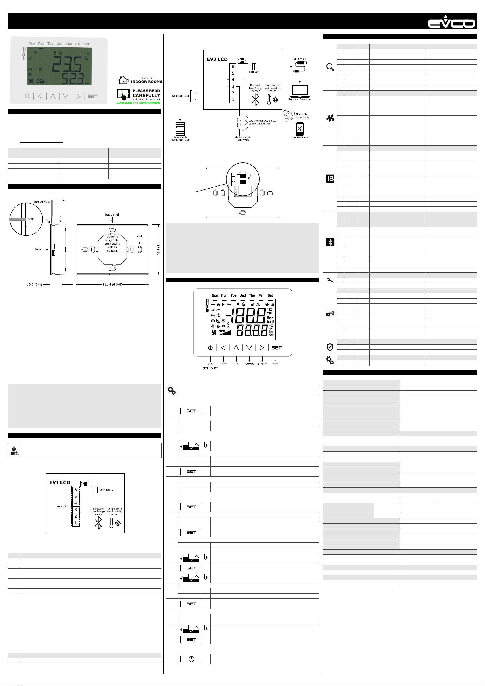
2.1 Connettori e parti
Signific to.
Connettore 1
N.
DESCRIZIONE
1 riferimento port INTRABUS
2 segn le port INTRABUS
3
liment zione dispositivo (12 VAC/DC); se il dispositivo è liment to in corrente con-
tinu , colleg re il termin le neg tivo
4
liment zione dispositivo (12 VAC/DC); se il dispositivo è liment to in corrente con-
tinu , colleg re il termin le positivo
5 riserv to
6 riserv to
Connettore 2
Port USB.
Sensore Bluetooth Low Energy
Disponibile solo in EVJD900N2VWIV ed EVJD920N2VWIV.
Sensore di temperatura e di umidità
Disponibile solo in EVJD920N2VWIX ed EVJD920N2VWIV.
2.2 Collegamento elettrico
Esempio di colleg mento elettrico.
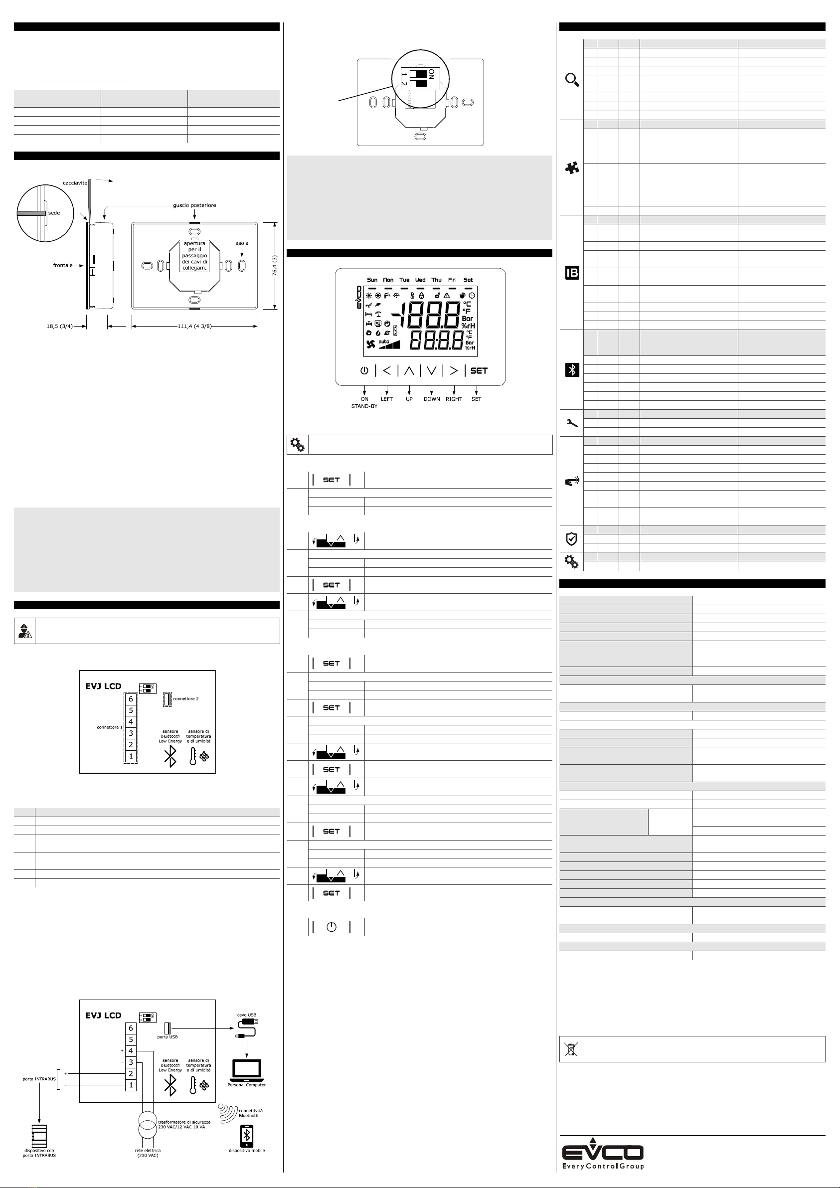
2.3 Predisposizione per la programmazione
Per predisporre il dispositivo per l progr mm zione, posizion re il micro switch 1 in ON.
AVVERTENZE PER IL COLLEGAMENTO ELETTRICO
- se si utilizz no vvit tori elettrici o pneum tici, moder re l coppi di serr ggio
- se il dispositivo è st to port to d un luogo freddo uno c ldo, l’umidità potrebbe ver
condens to ll’interno; ttendere circ un’or prim di liment rlo
- ccert rsi che l tensione di liment zione, l frequenz elettric e l potenz elettric
rientrino nei limiti riport ti nel c pitolo DATI TECNICI
- scolleg re l’ liment zione prim di procedere con qu lunque tipo di m nutenzione
- non utilizz re il dispositivo come dispositivo di sicurezz
- per le rip r zioni e per inform zioni rivolgersi ll rete vendit EVCO; eventu li resi
sprovvisti del guscio posteriore non verr nno ccett ti.
3 IN ERFACCIA U EN E
3.1 Configurazione del dispositivo
ATTENZIONE
Interrompere l’ liment zione dopo l modific dell configur zione.
Accesso ll procedur .
1. Tocc re per 7 s il t sto DOWN.
Il displ y visu lizzerà:
Rig superiore Menu
Rig inferiore InFo
Accesso un menù.
2. Tocc re il t sto UP o il t sto DOWN per selezion re un menù.
Il displ y visu lizzerà:
Rig superiore Menu
Rig inferiore nome del menù.
3. Tocc re il t sto SET.
4.
Tocc re il t sto UP o il t sto DOWN per selezion re un p r me-
tro.
Il displ y visu lizzerà:
Rig superiore il p r metro
Rig inferiore il v lore del p r metro
Impost zione dei p r metri di configur zione del menù “PAr”.
3. Tocc re il t sto SET.
Il displ y visu lizzerà:
Rig superiore PSU
Rig inferiore 0000
4. Tocc re nuov mente il t sto SET.
Il displ y visu lizzerà:
Rig superiore PSU
Rig inferiore un v lore l mpeggi nte
5. Tocc re il t sto UP o il t sto DOWN per impost re “-019”.
6. Tocc re il t sto SET.
7.
Tocc re il t sto UP o il t sto DOWN per selezion re un p r me-
tro.
Il displ y visu lizzerà:
Rig superiore il p r metro
Rig inferiore il v lore del p r metro
8. Tocc re il t sto SET.
Il displ y visu lizzerà:
Rig superiore il p r metro
Rig inferiore il v lore del p r metro l mpeggi nte
9. Tocc re il t sto UP o il t sto DOWN per impost re il v lore.
10. Tocc re il t sto SET.
Ritorno lle visu lizz zioni precedenti.
11. Tocc re più volte il t sto ON/STAND-BY.
4 PARAME RI DI CONFIGURAZIONE
N. PAR. DEF. MENÙ “InFo” (SOLO LETTURA) MIN... MAX.
1 Prn - numero progetto -
2 Pru - versione progetto -
3 Prr - revisione progetto -
4 FUu - versione firmw re -
5 FUr - revisione firmw re -
6 FUS - sottoversione firmw re -
7 HUu - versione h rdw re -
8 HUr - revisione h rdw re -
N. PAR. DEF. MENÙ “PAr” MIN... MAX.
9
BKIL
10
intensità b cklight
0... 100
15 non modific bile in
EVJD920N2VWIX ed
EVJD920N2VWIV
10
BKIt
241
timeout b cklight
0... 241 s
241 = sempre cceso
15 non modific bile in
EVJD920N2VWIX ed
EVJD920N2VWIV
11
EU3C
OFF bilit comp tibilità con Vled 3 On... OFF
N. PAR. DEF. MENÙ “nEt > IbuS” (SOLO LET.) MIN... MAX.
12
nOdE
4
nodo INTRABUS
1... 127
se EU3C = On, nOdE = 3
13
StAt - st to comunic zione INTRABUS OK... Err
14
n_rH
-
numero p cchetti INTRABUS ri-
cevuti
0... 999
15
n_tH
-
numero p cchetti INTRABUS
tr smessi
0... 999
16
nErr
-
numero ricezioni INTRABUS in
errore
0... 999
17
BAud
- b ud r te INTRABUS 19200
18
StPB 1 numero bit di stop INTRABUS 0... 2
19
PrtY 2 p rità INTRABUS 0... 2
N.
PAR.
DEF.
MENÙ “nEt > bLE” (SOLO LET.;
DISP. SOLO IN EVJD900N2VWIV
ED EVJD920N2VWIV)
MIN... MAX.
20
n_rH - numero p cchetti BLE ricevuti 0... 999
21
n_tH - numero p cchetti BLE tr smessi 0... 999
22
nErr - numero errori BLE intercett ti 0... 999
23
BAud
- b ud r te BLE 19200
24
StPB 1 numero bit di stop BLE 0... 2
25
PrtY 2 p rità BLE 0... 2
N. PAR. DEF. MENÙ “diAG” (SOLO LETTURA) MIN... MAX.
26
MEm - st to memori EEPROM OK... Err
27
PSU - st to tensione di liment zione OK... Err
N. PAR. DEF. MENÙ “dEb” MIN... MAX.
28
PSU - v lore tensione di liment zione -
30
AI1 - riserv to -
31
AI2 - riserv to -
32
AI3 - riserv to -
33
AI4 - riserv to -
34
tI2C
-
v lore temper tur sensore in-
corpor to
-
35
HI2C
-
v lore umidità sensore incorpo-
r to
-
N. PAR. DEF. MENÙ “dEb > un” MIN... MAX.
36
dO1 - riserv to -
37
AI1t - riserv to -
N. PAR. DEF. MENÙ “ConF” MIN... MAX.
38
PSU - riserv to -
5 DA I ECNICI
Scopo del dispositivo di com ndo: dispositivo di com ndo di funzion mento.
Costruzione del dispositivo di com ndo: dispositivo elettronico incorpor to.
Contenitore: utoestinguente bi nco.
C tegori di resistenz l c lore e l fuoco: D.
Dimensioni: 111,4 x 76,4 x 18,5 mm (4 3/8 x 3 x 3/4 in).
Metodo di mont ggio del dispositivo di co-
m ndo:
p rete (con t sselli e viti di fiss ggio) o in
sc tol d inc sso 502E o 503E (con viti di
fiss ggio).
Gr do di protezione fornito d ll’involucro: IP30.
Metodo di connessione:
morsettiere fisse vite per conduttori fino
1 mm²
connettore Micro USB femmin .
Lunghezze m ssime consentite per i c vi di colleg mento:
liment zione: 10 m (32,8 ft) port USB: 1 m (3,28 ft)
port INTRABUS: 10 m (32,8 ft).
Temper tur di impiego: d 0 40 °C (d 32 104 °F).
Temper tur di imm g zzin mento: d -20 70 °C (d -4 158 °F).
Umidità di impiego:
d l 5 l 95 % di umidità rel tiv senz con-
dens .
Situ zione di inquin mento del dispositivo di
com ndo:
2.
Conformità:
RoHS 2011/65/CE WEEE 2012/19/EU
regol mento REACH (CE) n. 1907/2006 EMC 2014/30/UE R&TTE 1999/5/CE.
Aliment zione:
12 VAC/DC
12 VAC (±15 %), 50/60 Hz (±3 Hz), m x.
10 VA non isol t
12 VDC (±15 %), m x. 10 W non isol t .
Metodo di mess terr del dispositivo di
com ndo:
nessuno.
Tensione impulsiv nomin le: 4 KV.
C tegori di sovr tensione: III.
Cl sse e struttur del softw re: A.
Visu lizz zioni: displ y LCD due righe e icone funzione
Buzzer di ll rme: incorpor to.
Sensori incorpor ti:
Bluetooth Low Energy (solo in
EVJD900N2VWIV ed EVJD920N2VWIV)
di temper tur e di umidità (solo in
EVJD920N2VWIX ed EVJD920N2VWIV).
C mpo di misur sensore di temper tur e di umidità integr to:
0... 40 °C (32... 104 °F) 10... 90 % di umidità rel tiv .
Porte di comunic zione:
1 port INTRABUS 1 port USB.
According to Europe n R&TTE Decl r tion of Conformity this device c n be used in the follow-
ing Countries: Austri , Belgium, Cyprus, Czech Republic, Denm rk, Estoni , Finl nd, Fr nce,
Germ ny, Greece, Hung ry, Irel nd, It ly, L tvi , Lithu ni , Luxembourg, M lt , Norw y, Po-
l nd Portug l, Slov ki , Sloveni , Sp in, Sweden, Switzerl nd, The Netherl nds nd The United
Kingdom.
N.B.
The device must be disposed of ccording to loc l regul tions governing the collection
of electric l nd electronic w ste.
This document nd the solutions cont ined therein re the intellectu l property of EVCO nd thus pro-
tected by the It li n Intellectu l Property Rights Code (CPI). EVCO imposes n bsolute b n on the full
or p rti l reproduction nd disclosure of the content other th n with the express pprov l of EVCO. The
customer (m nuf cturer, inst ller or end-user) ssumes ll responsibility for the configur tion of the de-
vice.
EVCO ccepts no li bility for ny possible errors in this document nd reserves the right to m ke ny
ch nges, t ny time without prejudice to the essenti l function l nd s fety fe tures of the equipment.
EVCO S.p.A.
Vi Feltre 81, 32036 Sedico (BL) ITALY
el. 0437/8422 | Fax 0437/83648
email info@evco.it | web www.evco.it