EveMotion HB-ES1000A User manual

1
EN
Owner’s Manual
Original Owner’s Manual – English
Electric- Scooter 1000W
Vehicle with electric engine
EN
PRIOR TO FIRST USE READ THIS MANUAL COMPLETELY AND ATTENTIVELY!
IMPERATIVELY FOLLOW THE SAFETY INSTRUCTIONS!
NONOBSERVANCE CAN LEAD TO PERILOUS INJURIES!
KEEP THIS MANUAL CAREFULLY!
The operating instructions in digital form can be found at:
http://eve-motion.com/support/ES-1000.htm

2
EN
Index
Index Page
1. Introduction ........................................................................................... 2
2. Scope of delivery .................................................................................. 3
3. Technical data ....................................................................................... 3
4. Safety instructions ................................................................................ 4-5
4.1 Intended Use ................................................................................... 4
4.2 General safety instructions .............................................................. 4
4.3 How to use the charging device ...................................................... 5
5. Part names .............................................................................................
6. Assembly ............................................................................................... 7-9
7. Adjustments .......................................................................................... 10
8. Battery .................................................................................................... 11
8.1 Charging your battery before putting into operation ........................ 11
8.2 Advice of battery disposal ................................................................ 11
9. Operation ............................................................................................... 12
10. Driving .................................................................................................. 13
11. Service and maintenance ................................................................... 14
12. Storage ................................................................................................. 15
13. Packaging ............................................................................................ 1
14. Warranty ............................................................................................... 1
15. EU-Declaration of Conformity ........................................................... 17
1. Introduction
We congratulate you on your new vehicle. In order to avoid damages to the scooter as well as injuries due to
inappropriate use, please read this manual attentively before operating. It is important that you understand and
follow the instructions of this owner’s manual.
Have fun with your new and innovative item!
Your EveMotion Team

3
EN
2. Scope of delivery
1. 1x Electric scooter
2. 1x 3 V battery package
3. 1x Cradle (adjustable)
4. 1x Seat (height adjustable)
5. 2x Ignition key
. 1x Tool kit
7. 1x Charger
8. 1x Owner’s manual
3. Technical data
Engine: 1000 Watt
Cooling system
:
air cooling
Battery: 3 V/ 12Ah
Speed: regulable by switch
1. level up to 5km/h
2. level up to 32km/h
Range: approx. 20km
Front brake:
wheel dis
c brake
Rear brake:
wheel disc brake
Front transmission: suspension fork
Rear transmission shock absorber
Front tyre: 10‘ inch // 2.50 - 10
Rear tyre: 10‘ inch // 2.50 - 10
Dimensions: 132x25x114cm (LxWxH)
Seat height: 80 – 94cm (adjustable)
Tare weight: 38kg
Advice:
The range and speed depend on the user weight, the surrounding temperature, the
driving style and the surface.

4
EN
4. Safety instructions
4.1 Intended use
Driving is prohibited in public areas, roads, bicycle lanes or sidewalks. Use your item only in private
areas, which are not accessible to public. Only drive with permission of the estate owner. Disregarding
these instructions may lead to perilous injuries.
Residual risk remains even when you are using this item properly. The following hazards may occur
regarding the way of construction and embodiment of this vehicle.
RESIDUAL RISK!
4.2 General safety instructions
People who are not familiar with this owner’s manual and unexperienced people are not allowed to use
this vehicle.
Only lend the scooter to people who are familiar with the item. Hand over the manual.
The scooter may only be used by adolescents aged 14 and older - under supervision. Not suitable for
children.
Children, pregnant women and people with disabilities as well as people who are intoxicated or under in-
fluence of drugs, alcohol or medicines are prohibited to use the vehicle.
Driving is prohibited in public areas, roads, bicycle lanes and sidewalks.
Never use a damaged item. Only use the vehicle when it’s orderly maintained.
Always keep sufficient safety distance to other people and objects.
You are only allowed to use the vehicle when you are in good shape.
Fatigue also leads to carelessness.
In order to avoid overcharging the machine and thus caused damages, you must not exceed the maxi-
mum payload (90kg).
Always wear checked security equipment (helmet, hand-, knee- and elbow-pads) to avoid severe injuries.
Do not wear loose clothes.
You should not use the scooter, when you are not protected properly.
Do not drive over obstacles, ice, snow, wet and slippery surfaces. Avoid obstacles like waste, little
branches and stones.
Never drive in the dark or in poorly illuminated areas. Never turn spontaneously while driving.
ATTENTION!
Avoid damages to your item!
Never jump with the scooter as it could break, otherwise.
Keep your scooter away from water and other liquids – risk of short circuits!
Do not open the item.
Do not exceed the max. payload and avoid driving on steep ascents as the engine could be damaged
due to overcharge, otherwise.
Modifications are prohibited. Never manipulate something at/in your item.
Fall due to lose of equilibrium, uneven ground, poor experience, inattentiveness, distraction
or misjudgement.
Perilous injuries due to fall and inappropriate equipment (helmet, hand-, knee- and elbow-
pads).

5
EN
4. Safety instructions
4.3 How to use the charging device
WARNING!
Electric shock hazard. Always use and charge your scooter in a dry environment. Never use the
scooter in a wet or moisty environment. Depose the item properly.
Use the charger only for charging your scooter’s battery. A specific charging device should only be used
for a designated specific battery as there is a fire risk, otherwise.
Only connect the line cord of the charging device to an isolated ground receptacle, which is readily ac-
cessible and was properly installed. The isolated ground respectable has to correspond with the net volt-
age according to the descriptive plate of the charging device. The isolated ground respectable has to re-
main readily accessible in case you should have to disconnect the line cord.
To disconnect the apparatus from the mains, pull the connector, not the line.
Lay the cables in a way you cannot stumble over.
Never bend or squeeze the line cord. Keep it away from hot surfaces, lubricants, moving parts and sharp
edges.
Make sure that enough air reaches the charging device. The charging device heats while charging make
sure that it is not covered.
Use your charging device only in dry indoor places and never outdoor. Use your charger only for your
scooter’s battery. Never use it to charge any other battery or non-rechargeable batteries.
Stop using your charger if the housing or electrical wiring is damaged or the charger does not work properly.
A damaged charger cannot be repaired and has to be scrapped. Only replace it by a new one which is
identical in construction. It is available at our customer support.

6
EN
5. Part names
engine throttle
switch
rotary gas handle
hand grip
brake lever right
brake lever left
battery display
ignition switch
battery box
one fold
clamping
fixation
front wheel
lateral upright
steering column
suspension fork
seat pole
engine cover
seat
rear wheel
handlebar
rear shock absorber
engine
footboard
handlebar clamp
Carton 1
Carton 2
Tool Set

7
EN
6. Assembly
Erecting the steering column
Push the single-lever clamp down (fig.11, fig.12).
Align the steering column until it locks into place
(fig.13, fig.14).
fig.4
fig
.
3
Assembling the front wheel
Insert the front axle [E] through the first fork half way
through as shown. Slide the sleeve [E1] over the
front axle (fig.7).
Then place the front wheel between the two fork
halves. Make sure that the brake disc is correctly
fitted. Now push the front axle through the front
wheel (fig.8).
Push the sleeve [E2] over the front axle and push it
through the second fork half (fig.9).
Now screw the nut onto the front axle and tighten it
firmly with a wrench (fig.10).
fig.12 fig.11
Aligning the front wheel fork
Remove the retention bolt from the shock absorber
holder on the front shock absorber (fig.1).
Fold the suspension fork in the direction of the shock
absorber holder (fig.2). Ensure that the suspension
fork joints are aligned upwards (fig.3, fig.4).
Now push the retention bolt removed earlier through
the suspension fork again (fig.5).
Tighten the nut. (fig. ).
Tip:
For easier front wheel mounting, tighten the nut
by hand only and tighten with a wrench only after
inserting the front wheel.
fig
.
14
fig
.
13
fig
.
fig
.
5
fig.8 fig.7
fig
.
10
fig.9
fig.2 fig.1

8
EN
6. Assembly
Handlebar
Place the handlebar clamp [M] on the steering
column (fig.15). Alternately tighten the Allen screws
on the left and right of the handlebar clamp until it is
firmly attached to the steering column (fig.1 ).
Remove the cover of the clamp by loosening the 4
Allen screws. Place the handlebar in the
corresponding recess (fig.17).
Replace the cover on the clamp and fasten it by
tightening the 4 Allen screws crosswise (fig.18).
fig.1 fig.15
fig.18 fig.17
Connecting the battery
Open the battery compartment by pulling the left
and right locking hooks outwards and opening the
flap upwards (fig.19, fig.20).
Insert the battery [H] together with the battery bag
into the battery compartment (fig.21).
Connect the battery cable to the vehicle plug-in
connection (fig.22).
Inserting the fuse
Open the fuse box, insert the fuse [D] and press it
firmly (fig.23, fig.24).
Close the fuse box and store it together with the
cables in the battery box.
Close the battery box and lock it with the two
locking hooks on the left and on the right (fig.25,
fig.2 ).
fig.24 fig.23
fig.2 fig.25
fig.20
fig
.
19
fig
.
22
fig.21

9
EN
6. Assembly
Safety notice:
After assembly check that all screws and nuts are tightened.
Rear mudguard / reflector
Mount the mudguard [B] to the mudguard bracket
using 4 screws (fig.27, fig.28, fig.29).
Insert the reflector [N] through the reflector holder
on the mudguard and fasten it with a nut (fig.30).
fig.28 fig.27
fig
.
30
fig
.
29
Mounting the seat / saddle
Insert the seat post [J] into the seat post bracket on
the running board (fig.31).
Secure the seat post with the safety bolt [K] (fig.32).
Place the saddle [L] on the seat post [J], align the
saddle and then tighten the saddle bolt (fig.33,
fig.34).
fig.32 fig.31
fig.34 fig.33

10
EN
7. Adjustments
Seat height
Loosen the fastener at the side of the seat pole (fig.9).
Now, adjust the seat to the required height and fix it
with the fastener (fig.10).
The marked area may not be exceeded (fig.11).
fig
.
10
fig
.
9
fig.11
Brake lever
Loosen the hexagon socket screw to adjust the brake
lever (fig.1).
The brake lever should be easily accessible for the
driver and should neither be too high nor too low
adjusted (fig.2).
Brake calliper
Loosen the screw nut at the brake calliper (fig.3).
Push the brake arm to its position and pull the Bowden
cable tight.
The brake pad should have a distance of approx. 1mm
left and right to the brake disc (fig.4).
fig
.
4
fig
.
3
Chain tension
The chain should not be too loose but also not too
tight. It should be moveable (approx. 5-7mm) up- and
downwards (fig.5).
To adjust the chain tension, loosen the screws nuts of
the rear wheel and the hexagon socket screw at the
brake calliper holder (fig. ).
Tighten or loosen the chain with the two chain
tensioner nuts (fig.7).
Tighten the screw nuts of the rear wheel and the
hexagon socket screw. Lubricate the chain with some
chain oil or chain grease (fig. 8).
fig.2
fig
.
1
fig
.
fig
.
5
fig.8 fig.7

11
EN
8. Battery
8.1 Charging of the battery
The ignition switch has to be turned “off” (fig. 1).
Firstly, connect the charger with the charging plug
of the vehicle. Then, connect the charger to the power
supply (fig. 2).
As soon as the charger’s LED turns red, the battery charges. If not, please check all plug connectors.
When the LED turns from red to green, the battery is entirely charged.
Disconnect the charging device from the vehicle’s charging socket, as a longer charging time could affect the
lifetime of the battery negatively.
8.2 Advice of battery disposal
As we are distributing products that contain batteries, we are obliged to point out the following:
Since you are an end-user, you are obligated to return used batteries. You can return used batteries to us if the
corresponding battery (new condition) is or was listed in our assortment. Please use our postal address. Alterna-
tively, you can give it back to provided locations (e. g. municipal collecting point or shops).
The images you find on the battery have the following meanings:
= Do not dispose the battery in household garbage
Pb
= The battery contains more than 0.004 % lead by weight
Cd
= The battery contains more than 0.002 % cadmium by weight
Hg
= The battery contains more than 0.0005 % mercury by weight
fig.2 fig.1
ATTENTION!
Prior to each charging process, you need to check if charger and battery are in good condition.
In case of a defect you must not use the any longer and you need to dispose these correctly.

12
EN
9. Operation
Before every ride, check the vehicle for deficiencies and loose screw connections. The vehicle may only be
started after a positive check-up. When starting, always pull the brake lever. The lateral upright has to be folded
up as it can cause accident if it has contact to the ground.
fig.
1. Pull one of the two brake levers (fig.1).
2. Turn the ignition key to „ON“ (fig.2).
3. Fold up the lateral upright (fig.3).
4. Now, release the brake lever and slowly turn
the gas handle (fig.4).
5. Turn the ignition key to “OFF” in order to turn of
the engine.
fig
.
2
fig
.
1
fig
.
4
fig
.
3
fig.5
13
EN
10. Driving
KG
KG
fig.8
fig.7
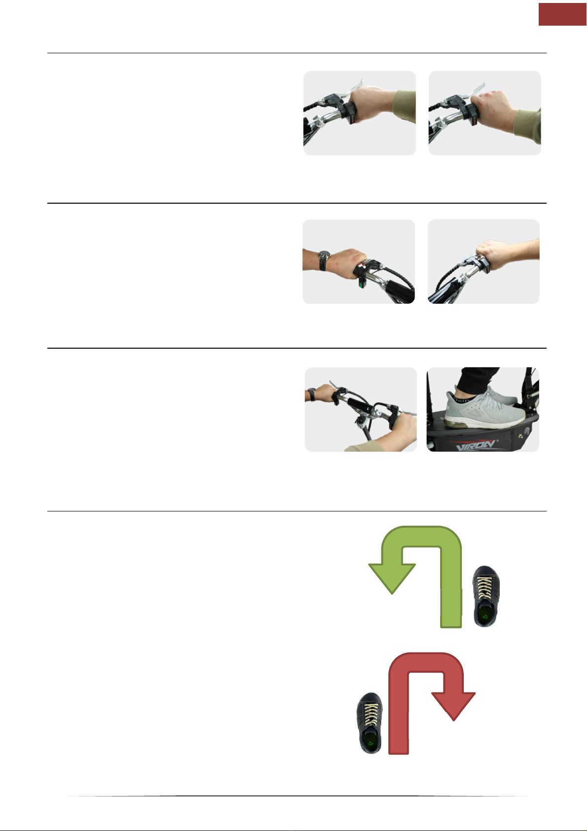
Brake lever
Pull the brake lever to stop the vehicle. The left brake
lever (fig.3) brakes the rear wheel.
The right brake lever brakes the front wheel (fig.4).
Pull both brake levers with same strength at every bra-
king process.
fig
.
4
fig.3
Starting
During the whole ride, both hands have always to be
at the handlebar (fig.5).
The feet have always to be on the footboard during
the ride (fig. ).
Don’t accelerate too much at the beginning as the
you could jerk the handlebar and lose the contact
to the ground.
Gas handle - throttle
Please get familiar with the gas handle.
Turn the gas handle slowly to the back (fig.1).
The vehicle now starts to drive slowly.
As soon as you release the gas handle, it will
rebound
and the vehicle will slow down (fig.2).
fig.2 fig.1
fig
.
fig
.
5
Driving bends
Adjust your speed to the bends and weather
conditions. Don’t accelerate quickly in bends and
avoid strong braking. In both situations you could lose
control over the vehicle. Lean into bend and support
yourself with the foot which is outwards.
Left-hand bend:
shift your weight to the left (fig.7).
Right-hand bend:
shift your weight to the right (fig.8).

14
EN
11. Service and maintenance
Drive chain
Regularly verify the chain tension and adjust it if nece-
ssary (fig.1).
Lubricate the driving chain – according to the use of the
vehicle – once a week with chain spray (fig.2).
Brake pads
The brake pads have to show a thickness of min. 1mm.
If the brake pads show less than 1mm thickness, both
brake pads have to be renewed (fig.3).
Maintenance interval
Driving chain check, lubricate 1x per week
Brake pads check 1x per week
Bowden cable check 1x per week
Screw connections check 1x per week
handlebar check 1x per week
fig.2
fig.1
brake pad
fig.3

15
EN
12. Storage
ATTENTION!
If you don’t use the vehicle over a longer period of time you should follow the next steps:
Remove battery
The ignition switch should be turned “off” (fig.1).
Open the battery box (fig.2).
Now, disconnect the battery from the cable tree of the
vehicle (fig.3).
Only store the battery in dry places at a temperature
level between minimum 5°C and maximum 30°C.
In order to avoid a total discharge of the battery, it
should regularly be charged (1x per month).
Remove the fuse
Pull off the cap from the fuse holder (fig.4).
Then, remove the fuse from the fuse holder (fig.5).
Covering the vehicle
Cover the vehicle with a blanket or a cloth in order to pro-
tect it from dust (fig. ).
Only store the vehicle in dry places at 5°C - maximum 30°C.
fig.4
fig.3
fig.2 fig.1
fig.
fig.5

16
EN
13. Packaging
The packaging is composed of recyclable materials. Dispose it environmentally compatible in provided
collection container.
14. Warranty
The legal warranty is valid for two years from the date of purchase. Save your payment document, it enables
you to make use of an eventual warranty service.
For any request regarding warranty, spare parts or replacement devices do not hesitate to contact us by mail or
E-Mail.
EveMotion GmbH
Marzahner Chaussee 213
12 81 Berlin
Germany
E-Mail: info@eve-motion.com
Website: www.eve-motion.com
The operating instructions in digital form can be found at:
http://eve-motion.com/support/ES-1000.htm

17
EN
15. EU- Declaration of Conformity
EU-Konformitätserklärung
Declaration of Conformity
Hiermit erklären wir EveMotion GmbH
We herewith declare, Marzahner Chaussee 213 12681 Berlin Germany
dass das nachfolgend bezeichnete Produkt in der von uns in Verkehr gebrachten Ausführung den
einschlägigen Anforderungen der nachfolgend genannten
EG-Richtlinien entspricht.
That the following Appliance complies with the appropriate basic safety and health requirements of the EU
Directive based on its design and type, as brought into circulation by us
Bei einer mit uns nicht abgestimmten Änderung des Produktes verliert diese Erklärung ihre
Gültigkeit.
In case of alteration of the product, not agreed upon by us, this declaration will cease to be valid
Bezeichnung des Produktes: Elektro-Scooter
Product Description: Electric Scooter
Modell-Nr.: HB-ES1000A HB-ES1000B
Model No :
Einschlägige EG-Richtlinien: EG Maschinenrichtlinie 2006/42/EG
Applicable EC Directives: EC Machineray Directive 2006/42/EC
EG Niederspannungsrichtlinie 2014/35/EU
EC Low Voltage Directive 2014/35/EU
EG Richtlinie über elektromagnetische Verträglichkeit 2014/30/EU
EC Directive of Electromagnetic Compatibility 2014/30/EU
RoHS Richtlinie 2011/65/EU
RoHS Directive 2011/65/EU
Angewandte harmonisierte Normen: EN ISO 12100:2010
Applicable harmonized standards: EN 60204-1:2006+A1:2009+AC:2010
EN 15194:2009+A1:2012
EN 61000-6-1:2007
EN 61000-6-3:2007+AC:2012
IEC 62321-8 ED 1.0
Unterlagenbevollmächtigter:
EveMotion GmbH
Representative for Documents: Marzahner Chaussee 213
12681 Berlin
Germany
Berlin, 01.08.2018 Unterschrift / Signature:
Angaben zum Unterzeichner: Michael Wendorf Geschäftsführer
Identification of the signatory: Michael Wendorf, CEO/Director
This manual suits for next models
1
Table of contents


