Ever Solar Eye User manual

Solar EyeUserManual
Edition <1.0>

Solar Eye User Manual V1.0
Page 2 of 24
Table of Contents
1.Introductions………………………………………………………….…3
1.1 Packing List……………………………………………………………..4
1.2 Safety and Notes……………………………………………………...…5
2. Product Installation…………………………………………………...…6
2.1 Connection Solar Bee and Straight Networking Cable………….………6
2.2 Solar Bee Hanging Installation………………………………….………7
2.3 SD Card in Solar Eye and Battery Installation Steps……………………8
2.4 Solar Eye Installation………………………………………………..…10
2.4.1Detachable Chassis Fixation……………………………………....…10
2.4.2WallMounting…………………………………………………….…11
3. Interface Introduction……………………………………….…………12
3.1 MainInterface………………………………………………………….12
3.2 Sub Interface……………………………………………………………13
4. Set & Operation…………………………………………………….…..14
4.1 Initial Setting…………………………………………………...…....…14
4.1.1 Set Time………………………………………………………........…14
4.1.2 Set Currency…………………………………………………….....…15
4.1.3 Set Yield Coefficient…………………………………………………15
4.1.4SetEmission Coefficient……………………………………..…..…16
4.2 Wireless Connection………………………………………………..…16
4.2.1 Connection Type………………………………………………....…17
4.2.2 Set Up Wireless Connection…………………………………………17
4.3AlarmWarningSetting……………………………………………..…18
4.4 Data Storage Interval Time Setting……………………………………19
4.5 Restore Factory Default Settings………………………………………19
4.6 History Energy and Power Value Yield View……………………..…19
5.Reference……………………………………………………………….21
6.ErrorMessage……………………………………………………….22
7.Contact………………………………………………………………….24
Solar Eye User Manual V1.0
Page 3 of 24
1. Introductions
Solar Eye isdesktop monitoringdevice, developedfor home andsmall
commercial PV solar system.This device is able to monitor up to 5 inverters
simultaneously, transfer data through wireless network and display relevant
data on the LCD.
Features:
●Integrated LargeLCD display
●Multiple display - Graphor barchart displayoptions
●Wireless Technology(Upto 150 meter inopenarea and up to 100 meterin
building)
●Retro fit onany EverSolar inverter, monitor up to 5inverters
●Micro SDcardstorage for history monitoringdata
●Real time monitoringofPower Generation, Export value andCarbon
Saving
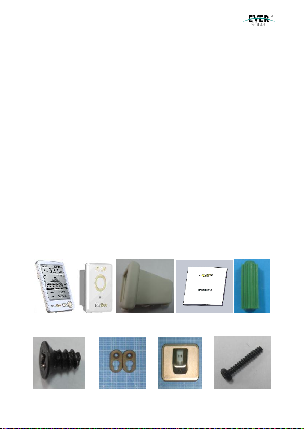
1.1 PackingList
The packing list of Solar Eyeas below:
A B C D E
F GH I

Solar Eye User Manual V1.0
Page 4 of 24
Table 1-1Packaging List (1)
Location
Quantity
Name
Purpose
A
1
Solar Eye
Displayterminal ofinverter data
B
1
SolarBee
Collect inverter data
C
1
WaterproofSeal Sets
Secure waterand dustprotectionof
Solar Bee (IP65)
D
1
Operating&
Installation Instruction
Productoperating &installation
instruction
E
4
wall plug
For Solar Bee wall mounting
F
2
ScrewST2.7× 6
Fix the suspensionloop to Solar Bee
G
2
Solar Bee Suspension
Loop
ForSolar Beewall mounting
H
1
The baseofSolar Eye
ForSolar Eyeinstallation on the table
I
4
Screw ST3× 25
ForSolar Bee&Solar Eyewall
mounting
1.2 Safetyand Notes
1)Read the instructions before installation
2)Disconnectinverterpowerbefore installingSolarBee
3)Ifthe product is damaged, please contact your local maintenance
center or return to the dealers/distributors for repair
4)Please doNOTtryto openthe Solar EyeandSolar Bee, or forceit in
anywayas itwill VOIDyour warranty andwewill not be able to
exchange it
5)Please donot put Solar Eye in the wateror anyotherliquids.
6)Please donot place SolarEye near heat orflame,or anyplace with
high humidityorlow temperature
7)Please handle the product carefully
9)Please keep theproduct awayfrom children
10)Please use theproduct under the environment withtemperature

Solar Eye User Manual V1.0
Page 5 of 24
ranging from -20℃to50 ℃, and relative humidity ≤ 80%
11)WhenSolar Eye isnot in use for a longtime, please remove the
batteryor cut offthe power.
2. ProductInstallation
The installationprocessincludes the installation ofSolar Bee andSolar Eye.
Please follow below steps.
2.1 Connecting Solar Bee and Straight Networking Cable
1) Please remove the square silica gel plug, andtheninsert network cable, as
shownin Fig2-1
Fig2-1Insert network cable
Attention: Connection cable isstandard CAT5network cable with RJ45
connectors, CAT5, CAT5E is compatible.
2) Fixthe accessories (waterproofseal sets) to Solar Bee, as shownin Fig2-2
Fig2-2Installationofwaterproof seal sets

Solar Eye User Manual V1.0
Page 6 of 24
2.2 Solar Bee Wall Attach Installation
1) Use the ST2.7*6 screws tofixtwosuspensionloops onto the pillars of
Solar Bee.Fig2-3 as below
Fig2-3Suspension loop installation
2) Drilltwoφ6holes on the wall with39mmspace distance as Fig2-4
Fig2-4Drill the wall mounting holes
Attention: Hold the handgrip tightly; keep right direction, noshaking to
prevent the damages to thewall andbiasof the holes. The depthof holes
must morethan30mm.Pleasekeepthesurfacecleanbefore measurement.
3) Use the rubber hammer totap wall plugs intothe holes.
4) Wring twoST3× 25screws into wall plugs, and keep the screwhead5mm
space outside. Fig2-5 as below

Solar Eye User Manual V1.0
Page 7 of 24
Fig2-5 Fix screws
5) Hangthe Solar Bee onthe screws fixedto the wall.Tightenthe screw with
a screwdriverslightly. Fig2-6 as below
Fig2-6Install Solar Bee
6) Connect Solar Bee andthe PV invertertogether withthe straight
networkingcable. Fig2-7 as below
Fig2-7Connect inverterandSolarBee
Solar Eye User Manual V1.0
Page 8 of 24
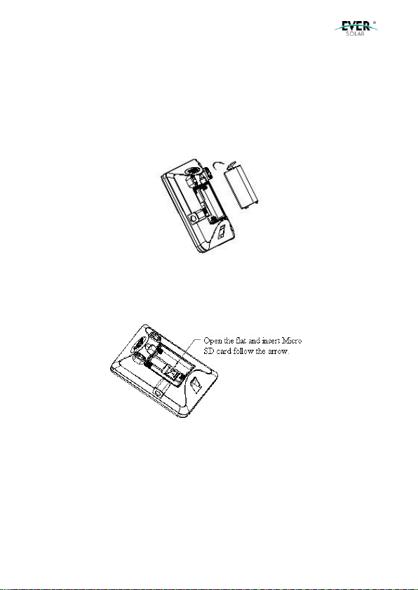
2.3 SD Card (Optional) in Solar Eye and BatteryInstallation
Solar Eye adopts SD card (compatible upto 4GB). Users is able to upgrade
Solar Eye Firmware through SD card.
1)Openthe batterycover ofSolarEye.Fig2-8 as below
Fig2-8 Openbattery cover
2)Put SD card intothe slot, thenlockthe MICROSD card clampingplate.
Fig2-9 as below
Fig2-9Insert SD card
3)Put three pieces AA alkaline battery intobattery box followingthe + -
marksasFig 2-10.

Solar Eye User Manual V1.0
Page 9 of 24
Fig2-10 Batteryloading
Warning: Make sure the battery polarity. The product alsocould be
powered by 4.5V DC adaptershowingin theFig2-10.
2.4 Solar Eye Installation
There are twoways for Solar Eye installation: one is onthe removable base,
the other wayis wall mounting.
2.4.1Detachable Chassis Fixation
Press the SolarEye bottomgroove intothe convexofbase. Witha sound of
clattering, installation will be finished. Fig2-11 as below:
Fig2-11 Solar Eyebase setting
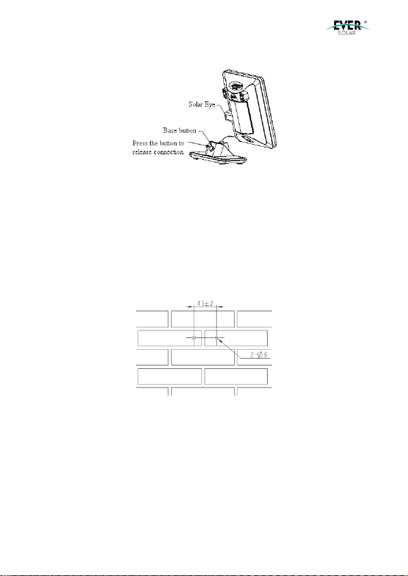
Ifwant toremove Solar Eye fromthebase, press the base button andrelease
connection. Fig2-12 as below:
Solar Eye User Manual V1.0
Page 10 of 24
Fig2-12 Remove Solar Eye frombase
Warning: When remove the base,there should be noforce incase of
mechanical damage.
2.4.2 Wall Mounting
1)Drill two φ6holes with43mmspace distance. Fig2-13 as below:
Fig2-13 Drill the wall mounting holes
Warning: Stayvertical angle between drillerand wall with noshake in
case of incline. The hole should be noless than 30mm deep. When
measurethe hole depth,clear the dust inside.
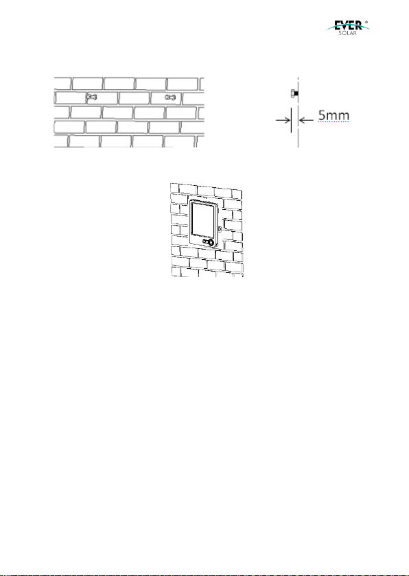
2)Place the wall plugs into the holes with the rubber hammer.
3)Wring the screws ST3× 25 into wall plugs, and keep the screwhead 5mm
Solar Eye User Manual V1.0
Page 11 of 24
space outside. Fig2-14 as below:
Fig2-14 Fixscrews
4)Hook the Solar Eye over the two screw nails.Fig 2-15 as below:
Fig2-15 Hook Solar Eyeonthe wall

Solar Eye User Manual V1.0
Page 12 of 24
3. Interface Introduction
3.1 Main Interface
Solar Eye maininterface as Fig3-1:
Fig3-1Solar Eye maininterface
Pos. Fig 3-1
Description
A
Date
B
Time
C
Powertrend
D
Sub menu
E
Gross generation
F
Intradaygeneration
G
Current generated power
H
Connected inverter quantity
I
Batterydisplay(when batterypower shortagehappens, it willtwinkle)
3.2 Sub Interface
Under main interface, press “enter” key toswitchamongENERGY, YIELD,
CO2andHISTORY interfaces.

Solar Eye User Manual V1.0
Page 13 of 24
1)ENERGY interface:displayE-today & E-total as Fig3-2
Fig3-2ENERGY Interface
2)YIELD interface:display E-today yield & E-total yieldas Fig3-3
Fig3-3YIELD Interface
3)CO2interface:displayCO2emission volumetodayandin total asFig3-4
Fig3-4CO2Interface
4)HISTORY interface:displayhourly,daily, weekly, monthlyandyearly
generatedelectricityas Fig3-5. For details, pls refer to chapter “4.6 check
generated electricity”.

Solar Eye User Manual V1.0
Page 14 of 24
Fig3-5HISTORYInterface
4. Set &Operation
Three keys “left” ( C ), “right” ( B ), and “enter” ( A ) are available as Fig 4-1,
whichcan helpachieve all functions.
Fig4-1Key Guide
4.1 Initial Setting
Initial setupis required for first time use. Users are allowedto change these
parameters asfollowing:
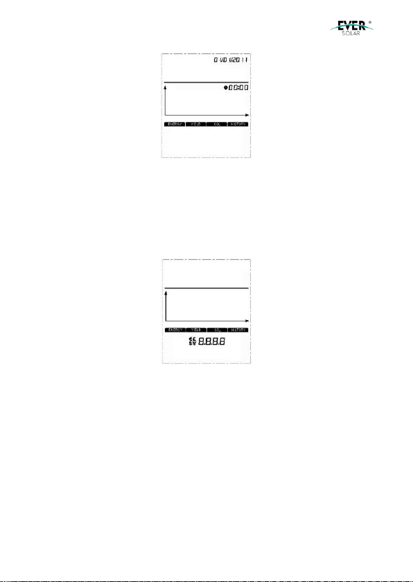
4.1.1 Set Time
Hold “Enter” key for 3 seconds for setting as Fig 4-2. At thisinterface,press
“left” & “right” key to change time, and switch to the next setting by “enter”
key. All time & dates will flashto indicate the settingis finished; at this time,
press “right” key to enter into currency setting interface.
Solar Eye User Manual V1.0
Page 15 of 24
Fig4-2Set Time
4.1.2 Set Currency
Currencysetting interface is asFig 4-3. Press “left” & “right” key to switch
among “€、£ 、$、¥” and then choose the target one by “enter” key. When
it’s finished, press “right” key to enter into yield coefficient setting interface.
Fig4-3Set Currency
4.1.3 Set Yield Coefficient
Yieldcoefficient indicates the yield per 1Kwhelectricitygeneratedfrom PV
inverterandits setting interface is as Fig4-4. Press “left” & “right” key to
change coefficient,andthenconfirm it by “enter” key. All digits flash to
indicate the setting is finished. At this time, press “right” key enter into
emissioncoefficient setting interface.

Solar Eye User Manual V1.0
Page 16 of 24
Fig4-4Set YieldCoefficient
4.1.4 Set Emission Coefficient
Emission Coefficient indicate the decreasedCO2volume (kg) per 1Kwh
electricitygeneratedfrom PV inverter andits settinginterface is as Fig4-5.
“left” & “right” key to change coefficient, andthen confirm it by “enter” key.
All digits flash to indicate the setting is finished. At this time, press “right”
keyenterinto maininterface.
Fig4-5Set Emission Coefficient
4.2 WirelessConnection
Solar Eye can be connected to EverSolar inverter (upto 5inverters) as the
followingtwo ways.
4.2.1 Connection Type
Type 1:One Solar Eye connects to multiple Solar Beeas Fig 4-6.

Solar Eye User Manual V1.0
Page 17 of 24
Fig4-6one Solar Eyeconnects toseveral SolarBee
Type 2:One Solar Eye connects toone Solar Bee, andthenthe Solar Bee
connects toseveral pieces ofinvertersas Fig 4-7.
Fig4-7one Solar Eyeconnects toone Solar Bee
4.2.2 Set Up WirelessConnection
1) Hold the Solar Bee under normal workingstate for 15 seconds, until LED
ofSolar Bee flashes, whichindicates Solar Bee has beenintoconnectionstate.
2) Hold “right” key of Solar Eye togo intoconnectionstate as Fig 4-8.At this
time,the channel Solar Bee stays in will show ontopleftcorner on SolarEye,
and press “left” & “right” key to choose channels Solar Bee stays in. For
example, icon indicates SolarBee stays inchannel 1.

Solar Eye User Manual V1.0
Page 18 of 24
Fig4-8Wireless ConnectionAdjust
3) Press “Enter” button on the Solar Eye to connect, while symbol
flashing,stopflashing after connectionis ready,while LEDis off. Solar
Eyegoes back tothe main menuautomatically after 1 minute.
4) Please repeat operationprocessabove again if the connectionfailure,
One Solar Eye connects toseveral Solar Bee(upto 10); avoidto settingto
same communication cannel.
4.3 Alarm WarningSetting
The alarm waning note user todeal withwheninvertererror happens, in the
main menu, press and hold “left” and “right” buttons enter the interface of
alarmwarningsetting, show as Fig 4-9. Press “left” and “right” to chose ON
or OFF, then press “enter” button quit the interface to the main menu.
Fig4-9interface ofalarm warningsetting

Solar Eye User Manual V1.0
Page 19 of 24
Setting alarm “on”, solar-eyealarm warningevery5 minutes tonote user
wheninvertererror happens.
4.4 Data Storage Interval Time Setting
Data storage interval means the frequencyofwriting data toSD card. In the
main menu, press and hold “left” button enter the interface of data storage
interval. as show in “Fig 4-1”. User can choose the interval time from 1 to 5
minutes by pressing “left” or “right” buttons, Then press “enter” button go
back tothe main menu.
Fig4-10 Interface ofdata storage interval
4.5 Restore FactoryDefaultSettings
In the main menu, you press and hold both “left” and ”right” buttons, while
switchonthe power. LCD displayin full screen, LED flashafter 3seconds,
thendevice restoreto default factory setting. After completion, device canbe
usedagainby switchonpower.
Attention: historydatawill be lost ifrecover to factorydefault setting.
therefore, copy the datain SD card before restore to factorydefault
setting!

Solar Eye User Manual V1.0
Page 20 of 24
4.6 HistoryEnergy and Power Value YieldView
Call up HISTORY menu, you press “right” button to view history data by
switching the unit of Y axis among “Hour”“Day”“Week”“Month”and “Year”
by pressing “right” button. Operation process show as below:
1)Hour:Press “right” button, you can view the energy and power
values/hour of last 34 hours yield by your PV system, Shown as in “Fig 3-1”
“B” m eans the time you check, ”F” means energy and power values yield in
this hour.
2)Day:Press “right” button, you can view the energyand power values/day
of this day yield by your PV system, Shown as in “Fig 3-1” “A” means the
data you check, ”F” means energy and power values yield in the day.
3)Week:Press “right” button, you can view the energy and power
values/week of last 34 weeks yield by your PV system, Shown as in “Fig 3-
1” “B” means the week you check, ”F” means energy and power values yield
inthisweek.
4)Month:Press “right” button, you can view the energy and power
values/monthoflast 34 monthsyield by your PV system. Shown as in “Fig
3-1” “A” means year you check, ”F” means energy and power values yield in
this month.
5)Year:Press “right” button, you can view the energy and power values/year
oflast 4 yearsyieldby your PV system. Shownas in “Fig 3-1” “A” means
year you check, ”F” means energy and power values yield in this year.
Table of contents
Popular Measuring Instrument manuals by other brands


Omntec
Omntec PROTEUS B installation manual

Haglof
Haglof DP II user manual

Agreto
Agreto HFM II user manual

PureAire
PureAire Air Check O2 KF-25 instruction manual

GE Wiring Devices & Specialty Products
GE Wiring Devices & Specialty Products GE5805WS6 user manual

LaserLiner
LaserLiner GreenLine-Laser 2 P operating instructions


