Everbilt 1005129161 User manual

USE AND CARE GUIDE
DUAL FLUSH VALVE KIT
Item #A2422
Model #1005129161
THANK YOU
products designed to enhance your home. Visit us online to see our full line of productsavailable for your home improvement needs.
flush kit
Thank you forchoosing Everbilt!
Questions, problems, missing parts? Before returning to the store,
call Everbilt Customer Service
8 a.m. - 7 p.m., EST, Monday - Friday, 9 a.m. - 6 p.m., EST, Saturday
1-800-305-1726
HOMEDEPOT.COM
create quality

GRACIAS
Apreciamos la confianza que ha depositado en Everbilt a través de la compra de este kit de descarga.
Nos esforzamos por crear continuamente productos de calidad diseñados para mejorar su hogar.
Visítenos en línea para ver nuestra línea completa de productos disponibles para sus necesidades de
mejoras para el hogar. ¡Gracias por elegir Everbilt!
GUÍA PARA USO Y CUIDADOS
KIT DE VÁLVULA DE DOBLE DESCARGA
¿Preguntas, problemas, partes faltantes? Antes de regresar a la tienda,
llame al Servicio al Cliente de Everbilt
De 8 a.m. a 7 p.m., hora del este, de lunes a viernes, de 9 a.m. a 6 p.m., hora del este, los sábados
1-800-305-1726
HOMEDEPOT.COM
Artículo n.º A2422
Modelo n.° 1005129161

2
Table of Contents
Table of Contents ..........................................................2
Safety Information .........................................................2
Warranty ........................................................................3
Pre-installation .....................................................................4
Tools needed .................................................................4
Package contents ........................................................... 5
Installation ................................................................... 6
Maintenance ................................................................ 12
Troubleshooting .......................................................... 13
Service Parts ................................................................ 14
Safety Information
For your safety and to ensure the best use of
the accessories, make sure to follow this
instruction. Please read the instructions
carefully to use them correctly before using.
1. Read the operation and installation
instructions carefully, and install them step by
step according to the instructions to avoid
product damage or human injury caused by
bad operation.
2. All information is compiled according to the
latest product information at the time of
publication. The company reserves the right to
change the characteristics, packaging or
supply of the product at any time without notice.
3. Do not use corrosive cleaners or solvents in
the water tank, or any related chemical
component agents or solvents containing
chlorine or calcium hypochlorite as they will
seriously damage the water tank accessories,
causing leakage. The company will not be
responsible for the failure to use the water tank
accessories or other joint damage due to the
use of the above cleaning agents or solvents.
4. Do not use parts not provided by our
company, such as glass glue, for the
installation of our accessories. Our company is
not responsible for damage caused by using
parts which are not provided by our company
for the installation of our accessories.
5. Use water temperature range: 2℃- 45℃.
6. Use pressure range: 0.02MPa-0.8MPa.
7. If the product is inconsistent with the actual
product, please refer to the actual product.
8. This device is not intended to be used as
retrofit device for 4.8 Lpf (1.28gpf) water closet.
9. Performance may vary since product was
not tested on all water closet models.
NOTE: If the product does not match the picture,
please refer to the actual product.

2
Tabla de contenido
Tabla de contenido .................................................................. 2
Información de seguridad ........................................................ 2
Garantía ................................................................................. 3
Antes de la instalaciόn .................................................................... 4
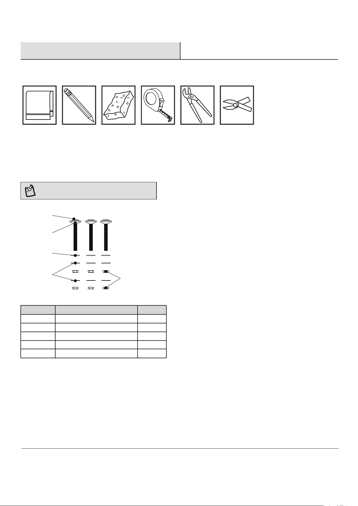
Herramientas necesarias...........................................................4
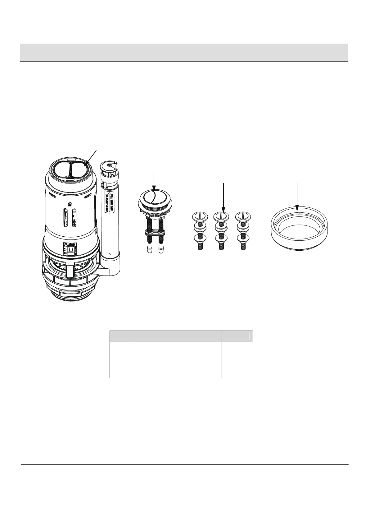
Contenido del paquete .............................................................. 5
Instalación ............................................................................... 6
Mantenimiento ........................................................................12
Resolución de problemas ..........................................................13
Piezas de repuesto ....................................................................14
Información de seguridad
Por su seguridad y para garantizar el mejor uso de
los accesorios, asegúrese de seguir estas
instrucciones. Por favor,lea las instrucciones
cuidadosamente para usarlos correctamente antes
de operar.
1. Lea las instrucciones de instalación
cuidadosamente e instálelas paso a paso
de acuerdo con las instrucciones para evitar
daños al producto o lesiones humanas causadas por
mal funcionamiento
2. Toda la información se compila de acuerdo con
la información más reciente del producto en el
momento depublicación. La empresa se reserva el
derecho de cambiar las características, embalaje o
suministro del producto en cualquier momento sin
previo aviso.
3. No use limpiadores corrosivos o disolventes en
el tanque de agua o cualquier químico relacionado
agentes componentes o solventes que contienen
hipoclorito de cloro o calcio ya que dañarán
seriamente los accesorios del tanque de agua,
causando fugas. La empresa no será
responsable de la falta de uso del tanque de agua
accesorios u otros daños en las articulaciones debido a
uso de los agentes de limpieza o solventes anteriores.
4. No utilice piezas no proporcionadas por nuestra
empresa, como cola de vidrio, para Ia
instalación de nuestros accesorios. Nuestra
empresa no se hace responsables de los daños
causados por el uso partes que no son
proporcionadas por nosotros para la instalación
de nuestros accesorios.
5. Use el rango de temperatura del agua:
2 ℃- 45 .
℃
6. Use el rango de presión: 0.02 MPa-0.8 MPa.
7. Si el producto es inconsistente con el actual
producto, consulte el producto real.
8. Este dispositivo no está destinado a ser
utilizado como dispositivo de adaptación para
inodoro de 4.8 Lpf (1.28 gpf)
9. El rendimiento puede variar ya que el produc-
to no ha sido probado en todos los modelos de
inodoros.
NOTA: Si el producto no coincide con la imagen,
por favor consulte al producto real

3 HOMEDEPOT.COM
Please contact 1-800-305-1726 for further assistance.
Warranty
LIMITED THREE-YEARS EXPRESS WARRANTY
Subject to the “Exclusions” set forth below, the manufacturer promises to the consumer to repair, or
replace any part of this plumbing product which proves to be defective in workmanship or materials
under normal use for three years from the date of purchase. All costs of removal, transportation and
reinstallation to obtain warranty service shall be paid by the consumer. During this “Limited Three Years
Express Warranty”, the manufacturer will provide, subject to the “Exclusions” section set forth below,
all replacement parts free of charge, necessary to correct such defects. This “Limited Three Years
Warranty” is null and void if this plumbing product has not been installed and maintained in
accordance with all written instructions accompanying the product.
EXCLUSIONS: THE MANUFACTURER SHALL NOT BE LIABLE FOR INCIDENTAL OR
CONSEQUENTIAL DAMAGES, INCLUDING COSTS OF INSTALLATION, WATER DAMAGE,
PERSONAL INJURY OR FOR ANY DAMAGES RESULTING FROM ABUSE OR MISUSE OF THE
PRODUCT, FROM OVERTIGHTENING OR FROM FAILURE TO INSTALL OR MAINTAIN THIS
PLUMBING PRODUCT IN ACCORDANCE WITH THE WRITTEN INSTRUCTIONS, INCLUDING
USE OF NOT RT’s PARTS.
Do not use corrosive cleaners or solvents in the water tank, or any related chemical component
agents or solvents containing chlorine or calcium hypochlorite as these will seriously damage the
water tank accessories, causing leakage. The company will not be responsible for the failure to use
the water tank accessories or other joint damage due to the use of the above cleaning agents or
solvents. Do not use parts not provided by our company, such as glass glue, for the installation of our
accessories. Our company is not responsible for damage caused by using parts which is not provided
by our company for the installation of our accessories.

3 Por favor, comuníquese al 1-800-305-1726
para recibir asistencia adicional.
Garantía
GARANTÍA EXPRESA LIMITADA DE TRES AÑOS
Sujeto a las "Exclusiones" establecidas a continuación, el fabricante promete al consumidor reparar,
o reemplazar cualquier parte de este producto de plomería que demuestre ser defectuoso en mano
de obra o materiales bajo uso normal durante tres años a partir de la fecha de compra. Los costos
de traslado, transporte y la reinstalación para obtener el servicio de garantía correrá a cargo del
consumidor. Durante este tiempo limitado de tres años de garantía expresa, el fabricante
proporcionará dicha garantía, sujeto a la sección "Exclusiones" que se establece a continuación,
Todas las piezas de repuesto necesarias para corregir los defectos son gratuitas. Esta "Garantía
limitada de tres años" es nula si este producto de fontanería no se ha instalado y mantenido de
acuerdo con todas las instrucciones escritas que acompañan al producto.
EXCLUSIONES: EL FABRICANTE NO SERÁ RESPONSABLE POR INCIDENTES O
DAÑOS CONSECUENTES, INCLUIDOS LOS COSTOS DE INSTALACIÓN, DAÑO POR AGUA,
LESIONES PERSONALES O POR CUALQUIER DAÑO RESULTANTE DEL ABUSO O MAL USO
DEL PRODUCTO, POR APRIETE EXCESIVO O POR FALLA AL INSTALAR O MANTENER ESTE
ARTICULO DE FONTANERÍA DE ACUERDO CON LAS INSTRUCCIONES ESCRITAS INCLUIDAS.
No use limpiadores corrosivos o solventes en el tanque de agua, o cualquier componente químico
relacionado agentes o solventes que contengan hipoclorito de cloro o calcio ya que estos dañarán
seriamente los accesorios del tanque de agua, causando fugas. La compañía no será responsable
por la falta de uso los accesorios del tanque de agua u otros daños en las juntas debido al uso de los
agentes de limpieza anteriores o disolventes. No utilice piezas no proporcionadas por nuestra
empresa, como cola de vidrio, para la instalación de nuestros accesorios. Nuestra empresa no se
hace responsable de los daños causados en estos casos.

4
Pre-installation
TOOLS REQUIRED
HARDWARE INCLUDED
NOTE: Hardware not shown to actual size.
Wrench Diagonal pliersRulerSpongePencilTowel
C1
C2
C3
C4 C5
C1
C2
C3
C4
C5
Bolt
Rubber gasket
Flat gasket
Gasket
Nut
3
3
3
6
6
Part Description Quantity

4
Antes de la instalación
HERRAMIENTAS NECESARIAS
Herraje incluido
Nota: Las piezas no se muestran en su tamaño real
Llave Inglesa Alicates diagonalesMetroEsponjaLapizToalla
C1
C2
C3
C4 C5
C1
C2
C3
C4
C5
Tornillo
Arandela plástica
Arandela plana
Junta
Tuerca
3
3
3
6
6
Pieza Descripción Cantidad

5
Pre-installation
PACKAGE CONTENTS
A
BCD
Part Description Quantity
A Flush valve 1
B Push button 1
C Bolt 3
D Gasket 1
HOMEDEPOT.COM
Please contact 1-800-305-1726 for further assistance.

Por favor, comuníquese al 1-800-305-1726
para recibir asistencia adicional.
5
Antes de la instalación
CONTENIDO DEL PAQUETE
A
BCD
Pieza Descripción Cantidad
A Válvula de descarga 1
B Botón de descarga 1
C Tornillos de fijación 3
D Junta 1

6
Installation
1. Marking water levels
1 2
1 2
3
A. Remove the water tank lid and mark the water level with a pencil.
B. Turn off water supply switch and press the half-flush button. When flush finishes, mark the residual
water level of the half flush.
C. Turn on the water supply switch. When the water inlet finishes,turn off the water supplyswitch.
Press full flush button. When the flush finishes, mark the residual water level of the full flush.
D. Drain the residual water in the tank and absorb water with a sponge.
E. Remove the water supply pipe.
2. Preparing the water tank
A. Measure and record the overflow height of the existing valve body in the water tank.
B. Observe the position of full and half flush buttons in the water tank and the direction of the overflow
pipe.
C. Prepare a relatively flat place for the removed water tank. Place a towel on the flat position to
prevent damage to the water tank and avoid sliding of the water tank.
Working water level
Half flush
remaining
water level Full flush
remaining
water level
Half flush
push button Full flush
push button
Overflow
CL line
Overflow Height

6
Instalación
1.MARCAR LOS NIVELES DE AGUA
A. Retire la tapa del tanque de agua y marque el nivel del agua con un lápiz.
B. Cierre la llave de suministro de agua y presione el botón de media descarga. Cuando
termine la descarga, marque el nivel de agua residual en el tanque con el lápiz.
C. Abra la llave de suministro de agua. Cuando termine la entrada de agua, cierre la
llave de suministro de agua. Presione el botón de descarga completa. Cuando finalice la descarga,
marque el nivel de agua residual de la descarga completa.
D. Drene el agua residual en el tanque y absorba el agua restante con una esponja.
E. Retire la tubería de suministro de agua.
2. PREPARAR EL TANQUE DE AGUA
A. Mida y registre la altura de desagüe del cuerpo de la válvula existente en el tanque de agua.
B. Observe la posición de los botones de descarga completa y media en el tanque de agua y la
dirección del tubo de desagüe.
C. Prepare un lugar relativamente plano para el tanque de agua extraído.
Coloque una toalla en la posición plana para evitar daños al tanque de agua y evitar el deslizamiento
del tanque de agua.
1 2 Botón de
media descarga Botón de
descarga
completa
Tubo de
desagüe
Nivel máximo
de agua
Altura del desagüe
1 2 3
Media
descarga,
nivel de agua
residual
Nivel de agua
Descarga
completa,
nivel de agua
residual

1
1
2
3
7
Installation (continued)
3. Removing the water tank
4. Preparing the flush valve
A. Use a screwdriver or open-end wrench to loosen the connection bolts between the water tank and
bowl, and remove the connection bolts.
B. Remove the water tank and place it in the prepared flat position.
C. Remove the rubber gasket. Unscrew the lock nut and the flush valve.
A. Rotate the valve body (A1) and remove it from the base (A2).
B. Loosen the lock nut (A3) and remove it from the base (A2).
C. Rotate the adjustable overflow pipe (A4) to unlock it. Adjust the overflow port height (OL) up and
down, measure the distance from the base seal to the overflow pipe rim, and ensure that the overflow
height is consistent or close to 2A measurement data. Afterwards, rotate the adjustable overflow pipe
(A4) to lock it.
NOTE: The adjusted overflow height OL should be lower than critical water level CL, and the distance must be greater than
or equal to 25mm.
Water
Tank
Bolt
Bowl
3
Rubber Gasket
Locknut
A1
A2
A3
Unlock
Locked
Overflow cap
A4
HOMEDEPOT.COM
Please contact 1-800-305-1726 for further assistance.

1
2
3
7
Instalación (Continuación)
3. Retirar el tanque de agua.
4. Preparando la Válvula de descarga
A. Use un destornillador o una llave inglesa para aflojar los pernos de conexión entre el tanque de
agua y taza de WC, y retire los pernos de conexión.
B. Retire el tanque de agua y colóquelo en la posición plana preparada.
C. Retire la junta de goma. Desenrosque la tuerca de seguridad y la válvula de descarga.
A. Gire el cuerpo de la válvula (A1) y retírelo de la base (A2).
B. Afloje la contratuerca (A3) y retírela de la base (A2).
C. Gire el tubo de rebose ajustable (A4) para desbloquearlo. Ajuste la altura del puerto de
desbordamiento (OL) hacia arriba y hacia abajo, mida la distancia desde el sello de la base hasta el
borde de la tubería de desagüe y asegúrese de que la altura de desborde es consistente o cercana a
los datos de medición de 2A. Luego, gire la tubería de rebose ajustable (A4) para bloquearlo.
NOTA: La altura de desbordamiento ajustada OL debe ser menor que el nivel crítico de agua CL, y la distancia debe
ser mayor que o igual a 25 mm.
A1
A2
A3
Cerrado abierto
Altura del desagüe
A4
1
Tornillos
Taza
3
Junta de goma
Tornillo de
fijación
Tanque de
agua
Por favor, comuníquese al 1-800-305-1726
para recibir asistencia adicional.

2
5. Installing the flush valve
6. Reinstalling the water tank
8
Installation (continued)
A. Connect the bolts (C) with rubber gaskets, flat washers,
washers, and nuts onto the bolt holes of the water tank and
tighten.
B. Place the water tank on the bowl, and tighten in place using
the second set of washers and nuts included with the bolts (C).
C. Insert the refill tube into the white cap of the overflow pipe (A4).
NOTE: Do not overtighten to avoid damaging
water tank.
NOTE: Do not overtighten to avoid damaging
water tank and bowl.
NOTE: The rim of the refill tube should be higher
than working water level to avoid water leakage.
A. Put the base (A2) into the installation hole of the tank and adjust overflow pipe (A4) position. Make
sure that the position of the overflow pipe is consistent with the direction observed in 2B (please
make sure that the overflow pipe and the base do not touch the inner wall of the water tank and other
water parts when adjusting).
B. Tighten the lock nut (A3). It is recommended to tighten the nut 3/4 turn. Do not overtighten
when tightening the nut to avoid damaging the water tank, bowl, and screw teeth.
C. Reinstall valve body (A1) on the base (A2), rotate the valve body (A1), and adjust the positions of
the full and half flush buttons to ensure the same direction as viewed in 2B.
D. Install the rubber gasket (D). The rubber gasket should be placed flat to ensure there is no leakage
between water tank and bowl.
D
A1
A2
A3
A2
A4
1 3
3
Bolt Gasket
Installation
sequence
Water Tank
Rubber Washer
Washer
Nut
Water Tank
Bowl
Washer
A4
Nut
C
1
2

2
5. Instalar la válvula de descarga
6. Reinstalar el tanque de agua
8
Instalación (Continuación)
A. Conecte los pernos (C) con juntas de goma, arandelas planas,
arandelas y tuercas en los orificios de los pernos del tanque de
agua y apretar.
B. Coloque el tanque de agua en la taza del WC y apriételo
usando el segundo conjunto de arandelas y tuercas incluidas
con los pernos (C).
C. Inserte el tubo de recarga en la tapa blanca del tubo de
rebose (A4).
NOTA: No apriete demasiado para evitar daños al
depósito de agua.
NOTA: No apriete demasiado para evitar daños al
depósito de agua.
NOTA: El borde del tubo de recarga debe ser más alto
que el nivel de agua de trabajo para evitar fugas de agua.
A. Coloque la base (A2) en el orificio de instalación del tanque y ajuste la posición del tubo de desagüe
(A4). Asegúrese de que la posición de la tubería de desagüe sea coherente con la dirección observada
en 2B (por favor asegúrese de que la tubería de desagüe y la base no toquen la pared interna del
tanque de agua y otras piezas de agua al ajustar).
B. Apriete la tuerca de seguridad (A3). Se recomienda apretar la tuerca 3/4 de vuelta. No apriete
demasiado al ajustar la tuerca para evitar dañar el tanque de agua, el tazón y la muesca del tornillo.
C. Vuelva a instalar el cuerpo de la válvula (A1) en la base (A2), gire el cuerpo de la válvula (A1) y ajuste
las posiciones de los botones de descarga completa y media para garantizar la misma dirección que se
ve en 2B.
D. Instale la junta de goma (D).
D
A1
A2
A3
A2
A4
1 3
3
Tornillo Junta
Secuencia de
instalación
Tanque de agua
Junta de goma
Arandela
Tuerca
Tanque de agua
Taza
Arandela
A4
Tuerca
C
1
2

1 2 3
1 2 3 4 5
7. Adjust the flush volume of the flush valve
8. Preparing the push button
9
Installation (continued)
A. Half flush volume adjustment: Adjust the half float up and down while pressing the clip. Decrease half
flush volume by moving half float upward and increase half flush volume by moving half float
downward.
B. Full flush volume adjustment 1: Adjust the full float up and down while pressing the clip. Decrease full
flush volume by moving full float upward and increase full flush volume by moving full float downward.
C. Full flush volume adjustment 2: Decrease full flush volume by moving the full adjustor upward and
increase full flush volume by moving full adjustor downward.
A. Close the water tank lid and measure the distance from the flush button (B) to the top of the water
tank lid with a tape measure, and record it as L1.
B. Loosen the lock nut (B1), unscrew the push rod (B2), and remove the positioning plate (B3).
C. Measure the length from the end of push rod (B2) with a tape measure, mark it at the L position
(L = L1-20mm) with a pencil, and cut off the excess with scissors.
D. Replace the push rod (B2) on the button (B) and tighten the lock nut (B1).
E. When L≥100mm, a positioning plate (B3) must be installed on the push rod (B2).The distance
between the position of the positioning plate and the lower end of the push rod is L3 (L3 = 40mm);
when L<100mm, there is no need for the positioning plate (B3).
NOTE: When adjusting the full float, the full adjustor must be set at scale 5. When adjusting full adjustor, the full float must
be set at scale 1.
Full Adjutor
3x magnification
Full
card
Full adjusting
float
3x magnification
Half
card
Half adjusting
float
3x magnification
B
B1
B3
B2
L1
Reserved part
L
L
L=L1-20mm
B3
Pressure
bar end
Note: when L≥100mm, it needs to be equipped with the localizer
when L <100mm, without the localizer
L2
L3
L2=L1-2mm
L3=40mm
HOMEDEPOT.COM
Please contact 1-800-305-1726 for further assistance.

7. Ajustar el volumen de descarga
8. Preparando el botón de descarga
9
Instalación (Continuación)
A. Ajuste del volumen de media descarga: ajuste la mitad del flotador hacia arriba y hacia abajo
mientras presiona el clip. Disminuya el volumen de descarga moviendo la mitad del flotador hacia arriba
y aumente el volumen de descarga media moviendo la mitad del flotador hacia abajo.
B. Ajuste del volumen de descarga completa 1: ajuste el flotador completo hacia arriba y hacia abajo
mientras presiona el clip. Disminución completa del volumen de descarga moviendo el flotador completo
hacia arriba y aumente el volumen de descarga completa moviendo el flotador completo hacia abajo.
C. Ajuste del volumen de descarga completa 2: disminuya el volumen de descarga completa moviendo
el ajustador completo hacia arriba y aumente el volumen de descarga completa moviendo el ajustador
completo hacia abajo.
A. Cierre la tapa del tanque de agua y mida la distancia desde el botón de descarga (B) hasta la parte
superior del agua del tanque con una cinta métrica y regístrela como L1.
B. Afloje la contratuerca (B1), desenrosque la varilla de empuje (B2) y retire la placa de
posicionamiento (B3).
C. Mida la longitud desde el extremo de la varilla de empuje (B2) con una cinta métrica, márquelo en
la posición L(L = L1-20mm) con un lápiz, y corte el exceso con unas tijeras.
D. Vuelva a colocar la varilla de empuje (B2) en el botón (B) y apriete la contratuerca (B1).
E. Cuando L≥100mm, se debe instalar una placa de posicionamiento (B3) en la varilla de empuje (B2)
entre la posición de la placa de posicionamiento y el extremo inferior de la varilla de empuje está a L3
(L3 = 40 mm); cuando L<100 mm, no hay necesidad de la placa de posicionamiento (B3).
NOTA: Al ajustar el flotador completo, el ajuste de descarga completa debe establecerse en la escala 5. Al ajustar el
ajuste de descarga completa, el flotador debe establecerse en la escala 1.
1 2 3
Ajuste de
descarga
completa
3X ampliaciòn
Descarga
completa
Botón
Ajuste de
descarga
completa
3X ampliación
Media
Botón
Flotador de
media descarga
3X ampliación
1 2 4 5
B
B1
B3
B2
L1
3
Reservar esta pieza
L
L
L=L1-20mm
B3
Final de Barra
de presión
Nota: cuando L≥100mm, debe estar equipado con punta de goma
Cuando L <100mm, se debe retirar la punta de goma
L2
L3
L2=L1-2mm
L3=40mm
Por favor, comuníquese al 1-800-305-1726
para recibir asistencia adicional.

1
4
2 3
9. Installing the push button
10. Adjusting the push button and flush volume
10
Installation (continued)
A. Remove the mounting nut (B4).
B. Put the push button (B) into the mounting hole on the water tank lid and pre-tighten the mounting
nut (B4).
C. Adjust the position of the buttons to ensure that the half push rod falls on the valve body's half flush
button, and the full push rod falls on the valve body's full flush button. Tighten the mounting nut (B4).
D. Adjustment of push rod: When the push lever is too long or too short, loosen lock nut (B1), then
rotate push rod (B2), adjust it up and down to the proper position, and finally tighten the lock nut (B1).
Check the installation of each component and confirm that tank fittings are installed normally, and
then adjust function according to the following steps:
A. Connect water supply pipe.
B. Adjustment of half flush function and flush volume: Turn on the water supply and then turn off the
water supply after the water tank is filled with water. Press the half flush button and observe whether
the residual water level is consistent with 1B WL. If not, adjust according to the method described
in 7A to ensure that the residual water level is consistent with or close to 1B WL.
C. Adjustment of full flush function and flush volume: Turn on the water supply and then turn off the
water supply after the water tank is filled with water. Press the half flush button of the flush valve and
observe whether the residual water level is consistent with 1C WL. If not, adjust according to
the methods described in 7B and 7C to ensure that the residual water level is consistent with or close
to 1C WL.
B
B4
B3
B1
B2
B
B4
Half flush
push button
Half flush
pressure bar
Half push
plate with “D”
Full push plate
with “O”
Full flush
pressure bar
2x magnification
5x magnificationZ
Full flush
push button
Half Flush Full Flush
Pressure bar is
too long
2x magnification 2x magnification
Fasten nut
Pressure bar

9. Instalar el botón de descarga
10. Ajustar el botón de descarga y el volumen de descarga
10
Instalación (Continuación)
A. Retire la tuerca de montaje (B4).
B. Coloque el botón (B) en el orificio de montaje en la tapa del tanque de agua y ajuste previamente el
montaje de la tuerca (B4).
C. Ajuste la posición de los botones para asegurarse de que la media varilla de empuje caiga en la
mitad del cuerpo de la válvula. El botón, y la varilla de empuje completa cae sobre el botón de descarga
completa del cuerpo de la válvula. Apriete la tuerca de montaje (B4).
D. Ajuste de la varilla de empuje: cuando la palanca de empuje es demasiado larga o demasiado corta,
afloje la contratuerca (B1), luego gire la varilla de empuje (B2), ajústela hacia arriba y hacia abajo a la
posición correcta, y finalmente apriete la contratuerca (B1).
Verifique la instalación de cada componente y confirme que los accesorios del tanque estén instalados
normalmente, y luego ajuste la función de acuerdo con los siguientes pasos:
A. Conecte la tubería de suministro de agua.
B. Ajuste de la función de media descarga y del volumen de descarga: abra el suministro de agua y
luego cierre el suministro de agua después de que el tanque de agua esté lleno de agua. Presione el
botón de media descarga y observe si el nivel de agua residual es consistente con 1B WL. Si no, ajuste
de acuerdo con el método descrito en 7A para asegurar que el nivel de agua residual sea consistente o
cercano a 1B WL.
C.Ajuste de la función de descarga completa y el volumen de descarga: abra el suministro de agua y
luego cierre el suministro de agua después de que el tanque de agua esté lleno de agua. Presione el
botón de media descarga de la válvula de descarga y observe si el nivel de agua residual es
consistente con 1C WL. Si no, ajuste de acuerdo a los métodos descritos en 7B y 7C para asegurar
que el nivel de agua residual sea consistente o cercano a 1C WL.
1 2 3
B
B4
B3
B1
B2
B
B4
Botón media
descarga
Barra de
presión de
media descarga
Superficie del
botón de media
descarga con “D”
Superficie del botón
de descarga compl
eta con “O”
Barra de presión
descarga completa
2x ampliación
5X ampliación
Botón de descarga
completa
Media
descarga Descarga
completa
4
La barra de presión
es demasiado larga
2X ampliación 2X ampliación
Tuerca de fijación
Barra de presión
This manual suits for next models
1
Table of contents
Languages:
Popular Control Unit manuals by other brands

Emerson
Emerson Rosemount 68 Series instruction manual

DayTronic
DayTronic 5M78 manual

Frequency Central
Frequency Central Whiteface Build documentation

Danfoss
Danfoss VLT MCA 121 EtherNet/IP manual

Honeywell
Honeywell VS8510 manual

ElMod
ElMod ThinkTank Tank Module PRO II Flex Instructions for Assembly and Handling