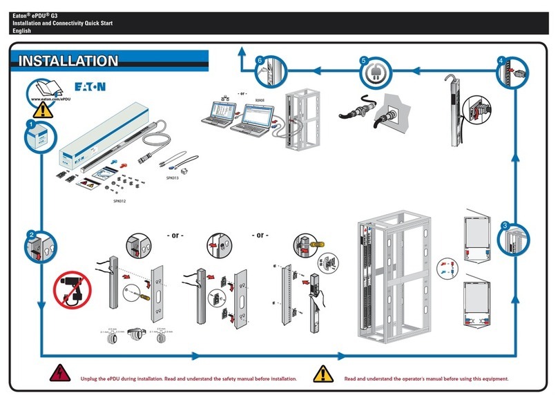
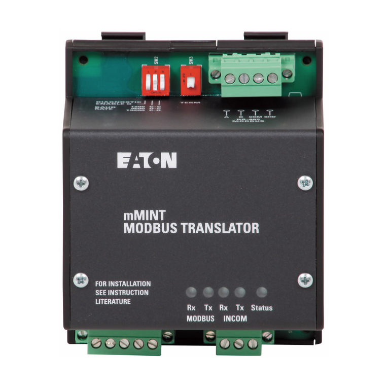
Eaton SystemStak DGM 3 40 Series User manual
Other Eaton Control Unit manuals
Eaton
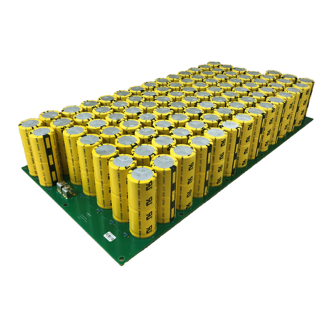
Eaton XVM PCBA Series User manual
Eaton
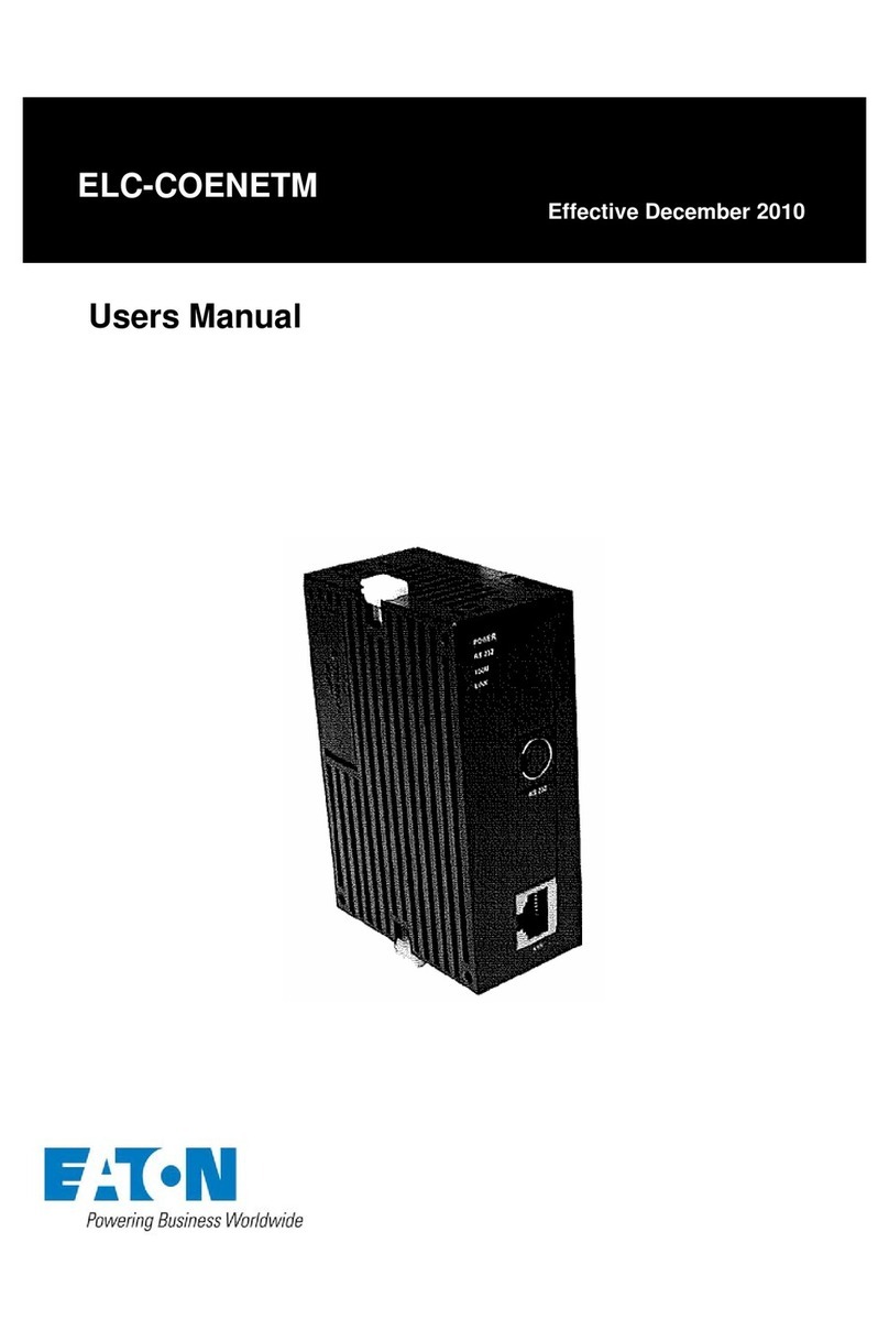
Eaton ELC-COENETM User manual

Eaton
Eaton Series NRX User manual
Eaton
Eaton NEMA 12 User manual
Eaton
Eaton 9395 SSBM User manual

Eaton
Eaton COOPER POWER SERIES User manual
Eaton
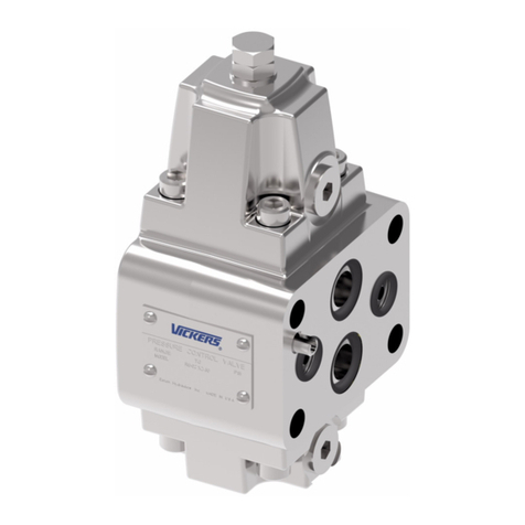
Eaton Vickers RF Series User manual
Eaton
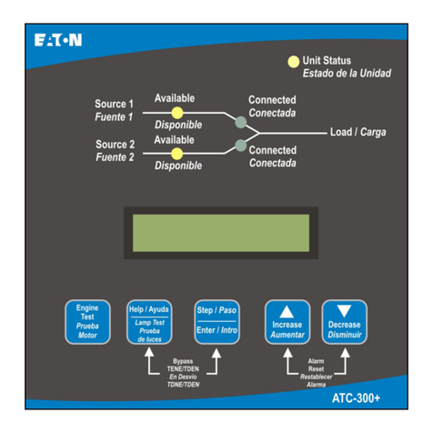
Eaton ATC-300+ User manual
Eaton
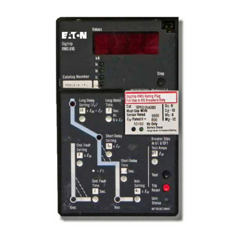
Eaton Cutler-Hammer Digitrip RMS 610 Manual
Eaton
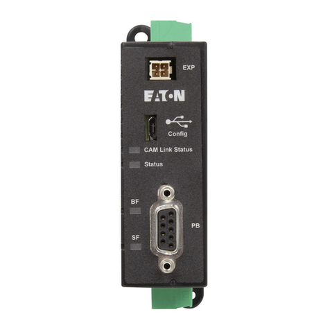
Eaton PXR-PCAM Manual
Eaton
Eaton eNMC2 User manual
Eaton
Eaton ELC-CADNET User manual
Eaton
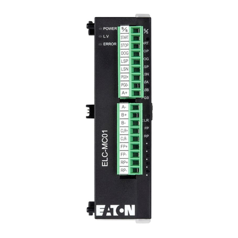
Eaton ELC-MC01 User manual
Eaton
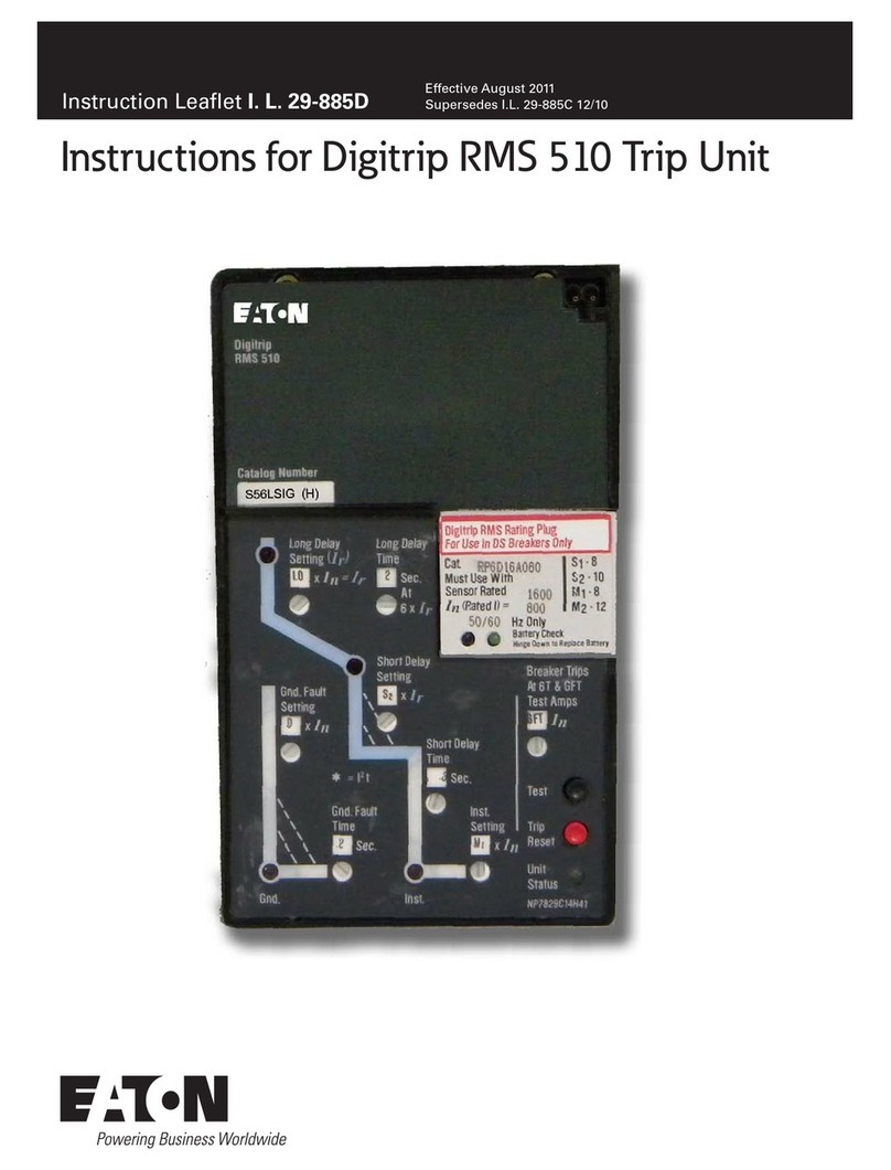
Eaton Cutler-Hammer Digitrip RMS 510 Manual

Eaton
Eaton Crouse-hinds series User manual

Eaton
Eaton COOPER POWER SERIES Installation and operating instructions
Eaton
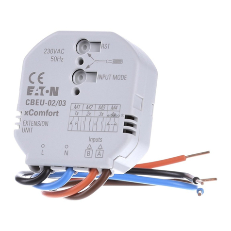
Eaton CBEU-02/03 User manual

Eaton
Eaton ELC-COENETM User manual

Eaton
Eaton XNE-1SWIRE User manual
Eaton
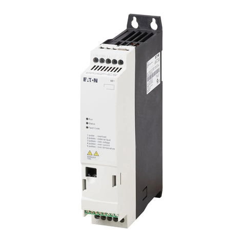
Eaton PowerXL DE1 series User manual
Popular Control Unit manuals by other brands

Festo
Festo Compact Performance CP-FB6-E Brief description

Elo TouchSystems
Elo TouchSystems DMS-SA19P-EXTME Quick installation guide

JS Automation
JS Automation MPC3034A user manual

JAUDT
JAUDT SW GII 6406 Series Translation of the original operating instructions

Spektrum
Spektrum Air Module System manual

BOC Edwards
BOC Edwards Q Series instruction manual

KHADAS
KHADAS BT Magic quick start

Etherma
Etherma eNEXHO-IL Assembly and operating instructions

PMFoundations
PMFoundations Attenuverter Assembly guide

GEA
GEA VARIVENT Operating instruction

Walther Systemtechnik
Walther Systemtechnik VMS-05 Assembly instructions

Altronix
Altronix LINQ8PD Installation and programming manual

