jcb JZ140 ZT User manual

Copyright © 2004 JCB SERVICE. All rights reserved. No part of this publication may be reproduced, stored in a retrieval system, or transmitted in any form or by any other means,
electronic, mechanical, photocopying or otherwise, without prior permission from JCB SERVICE.
World Class
Customer Support
Issued by JCB Technical Publications, JCB Service, World Parts Centre, Beamhurst, Uttoxeter, Staffordshire, ST14 5PA, England.
Tel +44 1889 590312 Fax +44 1889 593377
9803/6530-1
Publication No.
Service Manual
JZ140 ZTS
Section 1 - General Information
Section 2 - Care and Safety
Section 3 - Maintenance
Section B - Body and Framework
Section C - Electrics
Section E - Hydraulics
Section F - Transmissions
Section J - Track and Running Gear
Section K - Engine

Copyright © 2004 JCB SERVICE. All rights reserved. No part of this publication may be reproduced, stored in a retrieval system, or transmitted in any form or by any other means,
electronic, mechanical, photocopying or otherwise, without prior permission from JCB SERVICE.
World Class
Customer Support
Issued by JCB Technical Publications, JCB Service, World Parts Centre, Beamhurst, Uttoxeter, Staffordshire, ST14 5PA, England.
Tel +44 1889 590312 Fax +44 1889 593377
9803/6530-1
Publication No.
Section 1
General Information
Section 1 - General Information
Section 2 - Care and Safety
Section 3 - Maintenance
Section B - Body and Framework
Section C - Electrics
Section E - Hydraulics
Section F - Transmissions
Section J - Track and Running Gear
Section K - Engine
Find manuals at http://best-manuals.com/search?&s=JCB-9803-6530-1

Section 1 - General Information
1 - 1
9803-6530
1 - 1
Introduction
About this Publication
This publication is designed for the benefit of JCB
Distributor Service Engineers who are receiving, or have
received, training by JCB Technical Training Department.
These personnel should have a sound knowledge of
workshop practice, safety procedures, and general
techniques associated with the maintenance and repair of
hydraulic earthmoving equipment.
Renewal of oil seals, gaskets, etc., and any component
showing obvious signs of wear or damage is expected as
a matter of course. It is expected that components will be
cleaned and lubricated where appropriate, and that any
opened hose or pipe connections will be blanked to
prevent excessive loss of hydraulic fluid and ingress of
dirt. Finally, please remember above all else SAFETY
MUST COME FIRST!
The manual is compiled in sections, the first three are
numbered and contain information as follows:
1General Information - includes torque settings and
service tools.
2Care & Safety - includes warnings and cautions
pertinent to aspects of workshop procedures etc.
3Routine Maintenance - includes service schedules
and recommended lubricants for all the machine.
The remaining sections are alphabetically coded and deal
with Dismantling, Overhaul etc. of specific components,
for example:
The page numbering in each alphabetically coded section
is not continuous. This allows for the insertion of new
items in later issues of the manual.
Section contents, technical data, circuit descriptions,
operation descriptions etc. are inserted at the beginning
of each alphabetically coded section.
All sections are listed on the front cover; tabbed divider
cards align directly with individual sections on the front
cover for rapid reference.
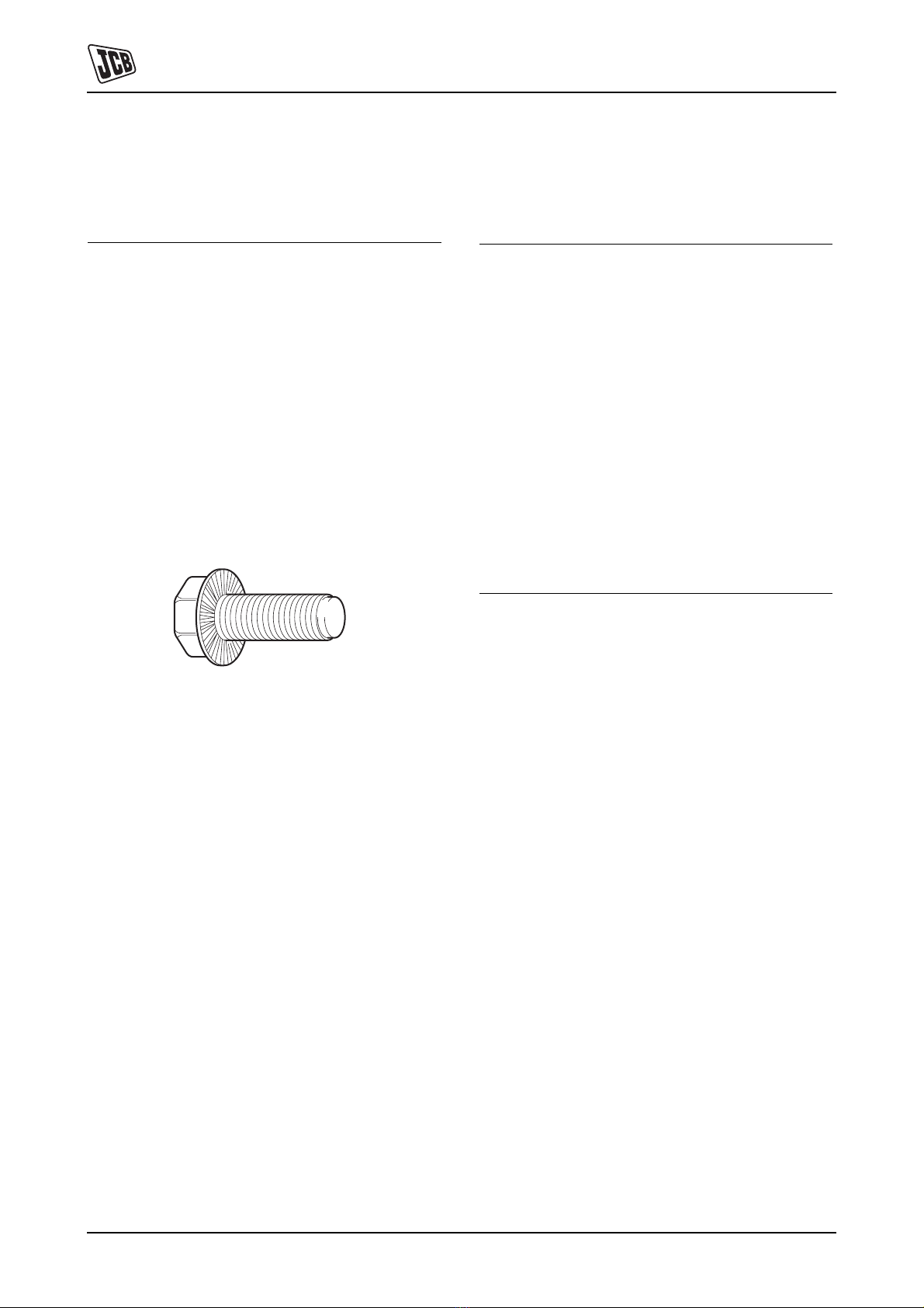
Where a torque setting is given as a single figure it may be
varied by plus or minus 3%. Torque figures indicated are
for dry threads, hence for lubricated threads may be
reduced by one third.
'Left Hand' and 'Right Hand' are as viewed from the rear
of the machine facing forwards.
AAttachments
BBody & Framework...etc.
This Service Manual covers the following machines:
JZ140
Find manuals at http://best-manuals.com/search?&s=JCB-9803-6530-1

Section 1 - General Information
Introduction
Schematic Codes
1 - 2
9803-6530
1 - 2
Schematic Codes
Colour Codes
The following colour coding, used on illustrations to
denote various conditions of oil pressure and flow, is
standardised throughout JCB Service Publications.
Red
Full Pressure: Pressure generated from operation of a service. Depending on application this
may be anything between neutral circuit pressure and MRV operating pressure.
Pink Pressure: Pressure that is above neutral circuit pressure but lower than that denoted by Red.
Orange Servo: Oil pressure used in controlling a device (servo).
Blue Neural: Neutral circuit pressure.
Green Exhaust:
Light Green Cavitation: Oil subjected to a partial vacuum due to a drop in pressure (cavitation).
Yellow Lock Up: Oil trapped within a chamber or line, preventing movement of components (lock up).
Find manuals at http://best-manuals.com/search?&s=JCB-9803-6530-1

Section 1 - General Information
1 - 3
9803-6530
1 - 3
Identifying your Machine
Identification Plates
Data Plate
Your machine has a Data Plate, located on the outside the
cab as shown at A. The machine serial number is
inscribed at Bwhich is the baseplate of the rear frame and
the engine number is at C.
Fig 1.
Fig 2.
Typical Vehicle Identification Number
(VIN)
1World Manufacturer Identification (SLP = JCB)
2Machine Type ( JZ = Tracked)
3Machine Model (14 = 140)
4Generation
5Year of Manufacture (1 = 2001, 2 = 2002, 3 = 2003, 4
= 2004, 5 = 2005, 6 = 2006)
6Manufacturers Location (E = England)
7Machine Serial Number (1137001)
B
A
732820
123456 7
SLP JZ 14 C 4 E 1137000
Find manuals at http://best-manuals.com/search?&s=JCB-9803-6530-1

Section 1 - General Information
Identifying your Machine
Identification Plates
1 - 4
9803-6530
1 - 4
Typical Engine Identification Number
If the engine is replaced by a new one, the data plate serial
number will be wrong. Either stamp the new number on
the plate or stamp out the old one. This will prevent the
wrong number being quoted when you order replacement
parts.
Fig 3.
aEngine Type (AB= 4 cylinder turbo)
bEngine Parts List
cCountry of Manufacture
dEngine Serial Number
eYear of Manufacture
abc d e
AB 50316 J 000001 2
C
Find manuals at http://best-manuals.com/search?&s=JCB-9803-6530-1

Section 1 - General Information
1 - 5
9803-6530
1 - 5
Torque Set t i n g s
Introduction - Zinc Plated Fasteners and Dacromet Fasteners
Some external fasteners on machines are assembled
using an improved type of corrosion resistant finish. This
type of finish is called Dacromet and replaces the original
Zinc and Yellow plating used on earlier machines.
The two types of fasteners can be readily identified by
colour and part number suffix as follows:
Note: As the Dacromet fasteners have a lower torque
setting than the Zinc and Yellow fasteners, the torque
figures used must be relevant to the type of fasteners.
Note: A Dacromet bolt should not be used in conjunction
with a Zinc and Yellow plated nut, as this could change the
torque characteristics of the torque settings further. For
the same reason, a Dacromet nut should not be used in
conjunction with a Zinc and Yellow plated bolt.
Note: All bolts used on JCB machines are high tensile and
must not be replaced by bolts of a lesser tensile
specification.
Note: Dacromet bolts, due to their high corrosion
resistance are used areas where rust could occur.
Dacromet bolts are only used for external applications.
They are not used in application such as gearbox and
engine joint seams or internal applications.
Fastener Type Colour Part Number
Zinc and Yellow Golden finish ‘Z’ (e.g. 1315/3712Z)
Dacromet Mottled silver finish ‘D’ (e.g. 1315/3712D)
Find manuals at http://best-manuals.com/search?&s=JCB-9803-6530-1

Section 1 - General Information
Torque Settings
Zinc Plated Fasteners (golden finish)
1 - 6
9803-6530
1 - 6
Zinc Plated Fasteners (golden finish)
Use only where no torque setting is specified in the text.
Values are for dry threads and may be within three per
cent of the figures stated. For lubricated threads the
values should be REDUCED by one third.
UNF Grade ‘S’ Bolts
Rivet Nut Bolts/Screws
Metric Grade 8.8 Bolts
Metric Grade 10.9 Bolts
Bolt size Torque Settings
Dia. (mm) Hexagon Nm kgf m lbf ft
(A/F) mm
1/4 6.3 7/16 14 1.4 10
5/16 7.9 1/2 28 2.8 20
3/8 9.5 9/16 49 5.0 36
7/16 11.1 5/8 78 8.0 58
1/2 12.7 3/4 117 12.0 87
9/16 14.3 13/16 170 17.3 125
5/8 15.9 15/16 238 24.3 175
3/4 19 1 1/8 407 41.5 300
7/8 22.2 1 5/16 650 66.3 480
1 25.4 1 1/2 970 99.0 715
1 1/4 31.7 1 7/8 1940 198.0 1430
1 1/2 38.1 2 1/4 3390 345.0 2500
Bolt size Torque Settings
Dia. (mm) Nm kgf m lbf ft
M3 3 1.2 0.12 0.9
M4 4 3.0 0.3 2.0
M5 5 6.0 0.6 4.5
M6 6 10.0 1.0 7.5
M8 8 24.0 2.5 18.0
M10 10 48.0 4.9 35.5
M12 12 82.0 8.4 60.5
Bolt size Torque Settings
Dia. (mm) Hexagon Nm kgf m lbf ft
(A/F) mm
M5 (5) 8 7 0.7 5
M6 (6) 10 12 1.2 9
M8 (8) 13 28 3.0 21
M10 (10) 17 56 5.7 42
M12 (12) 19 98 10 72
M16 (16) 24 244 25 180
M18 (18) 27 350 36 258
M20 (20) 30 476 48 352
M24 (24) 36 822 84 607
M30 (30) 46 1633 166 1205
M36 (36) 55 2854 291 2105
Bolt size Torque Settings
Dia. (mm) Hexagon Nm kgf m lbf ft
(A/F) mm
M6 (6) 10 16 1.6 12
M8 (8) 13 39 4 29
M10 (10) 17 78 8 57
M12 (12) 19 137 14 101
M16 (16) 24 343 35 253
M20 (20) 30 657 67 485
M24 (24) 36 1157 118 853
Find manuals at http://best-manuals.com/search?&s=JCB-9803-6530-1

Section 1 - General Information
Torque Settings
Zinc Plated Fasteners (golden finish)
1 - 7
9803-6530
1 - 7
Metric - All Internal Hexagon Headed
Cap Screws
Verbs Ripp Bolts
Fig 1.
Torque settings for these bolts are determined by the
application. Refer to the relevant procedure for the
required settings.
Hydraulic Hose to Adapter Connections
Hydraulic Adapter into Component
Connections with bonded washers
Diameter Torque Settings
mm Nm kgf m lbf ft
M3 2 0.2 1.5
M4 6 0.6 4.5
M5 11 1.1 8
M6 19 1.9 14
M8 46 4.7 34
M10 91 9.3 67
M12 159 16.2 117
M16 395 40 292
M18 550 56 406
M20 770 79 568
M24 1332 136 983
A34378
0
BSP Size Nm kgf m lbf ft
(inches)
1/8 14 1.4 10
1/4 24 2.5 18
3/8 33 3.3 24
1/2 44 4.8 35
5/8 58 6.0 43
3/4 84 8.6 62
1 115 11.8 85
1 1/2 244 24.9 180
BSP Size Nm kgf m lbf ft
(inches)
1/8 20 2.1 15
1/4 34 3.4 25
3/8 75 7.6 55
1/2 102 10.3 75
5/8 122 12.4 90
3/4 183 18.7 135
1 203 20.7 150
1 1/2 305 31 225
Find manuals at http://best-manuals.com/search?&s=JCB-9803-6530-1

Dacromet Fasteners (mottled silver finish)
9803-6530
Dacromet Fasteners (mottled silver finish)
Use only where no torque setting is specified in the text.
plating process: do not lubricate.
Metric Grade 8.8 Bolts
Metric Grade 10.9 Bolts
Metric Grade 12.9 Bolts
Bolt Size Torque Settings
Dia Nm kgf m lbf ft
M6 x 1.0 9 0.9 7
M8 x 1.25 22.5 2.3 17
M10 x 1.5 47.5 4.8 35
M12 x 1.75 80 8.2 59
M14 x 2 133 13.6 98
M16 x 2 200 20.4 148
M18 x 2.5 278 28.4 205
M20 x 2.5 392 40 289
M24 x 3 675 69 498
M30 x 3.5 1348 138 994
Bolt Size Torque Settings
Dia Nm kgf m lbf ft
M6 x 1.0 13.5 1.4 10
M8 x 1.25 35 3.6 26
M10 x 1.5 62.5 6.4 46
M12 x 1.75 115 11.7 85
M14 x 2 175 17.9 129
M16 x 2 300 30.6 221
M18 x 2.5 395 40 291
M20 x 2.5 559 57 412
M24 x 3 962 98 710
M30 x 3.5 1920 196 1416
Bolt Size Torque Settings
Dia Nm kgf m lbf ft
M6 x 1.0 15 1.5 11
M8 x 1.25 40 4.1 29
M10 x 1.5 80 8.2 59
M12 x 1.75 133 13.6 98
M14 x 2 225 23 166
M16 x 2 350 35.7 258
M18 x 2.5 463 47 342
M20 x 2.5 654 67 482
M24 x 3 1125 115 830
M30 x 3.5 2247 229 1657
Find manuals at http://best-manuals.com/search?&s=JCB-9803-6530-1

Section 1 - General Information
1 - 9
9803-6530
1 - 9
Service Tools
Numerical List Section B - Body and Framework
The tools listed in the table are special tools required for
removal and replacement of Body and Framework parts.
These tools are available from JCB Service.
Tools other than those listed will be required. It is
expected that such general tools will be available in any
well equipped workshop or be available locally from any
good tool supplier.
Part
Number
Description Tool Deta i l
Reference
4104/1310 Hand Cleaner Fig 1. (X1-10)
826/01099 M6 x 16mm Rivet Nut Fig 2. (X1-10)
826/01101 M6 x 19mm Rivet Nut Fig 2. (X1-10)
826/01102 M8 x 21mm Rivet Nut Fig 2. (X1-10)
826/01103 M8 x 18mm Rivet Nut Fig 2. (X1-10)
826/01104 M10 x 23mm Rivet Nut Fig 2. (X1-10)
826/01105 M10 x 26mm Rivet Nut Fig 2. (X1-10)
892/00842 Glass Lifter Fig 3. (X1-10)
892/00843 Folding Stand for Holding Glass Fig 4. (X1-10)
892/00844 Long Knife Fig 5. (X1-11)
892/00845 Cartride Gun Fig 6. (X1-11)
892/00846 Glass Extractor (Handles) Fig 7. (X1-11)
892/00847 Nylon Spatula Fig 8. (X1-11)
892/00848 Wire Starter Fig 9. (X1-11)
892/00849 Braided Cutting Wire Fig 10. (X1-11)
926/15500 Rubber Spacer Blocks Fig 11. (X1-12)
992/12300 12V Oven Fig 12. (X1-12)
992/12400 240V Oven 2 Cartridge Fig 13. (X1-12)
992/12600 240V Oven 6 Cartridge Fig 13. (X1-12)
992/12800 Cut-Out Knife Fig 14. (X1-12)
992/12801 ‘L’ Blades Fig 15. (X1-12)
Find manuals at http://best-manuals.com/search?&s=JCB-9803-6530-1

Section 1 - General Information
Service Tools
Tool Detail Reference Section B - Body and Framework
1 - 10
9803-6530
1 - 10
Tool Detail Reference Section B - Body and Framework
Note: Not all service tools are illustrated. Illustrations are
shown in tool number order.
Fig 1. 410/1310
Note: Special blend for the removal of polyurethane
adhesives
Fig 2.
Installation Tool Available from:
Bollhoff Fastenings Ltd.
Midacre
The Willenhall Estate
Rose Hill
Willenhall
West Midlands, WV13 2JW
Fig 3. 892/00842
Note: minimum 2 off - essential for glass installation, 2
required to handle large panes of glass. Ensure suction
cups are protected from damage during storage.
Fig 4. 892/00483
Note: - essential for preparing new glass prior to
installation..
Find manuals at http://best-manuals.com/search?&s=JCB-9803-6530-1

Section 1 - General Information
Service Tools
Tool Detail Reference Section B - Body and Framework
1 - 11
9803-6530
1 - 11
Fig 5. 892/00844
Note: - used to give extended reach for normally
inaccessible areas.
Fig 6. 892/00845
Note: - hand operated - essential for the application of
sealants, polyurethane materials etc.
Fig 7. 892/00846
Note: - used with braided cutting wire (below) to cut
out broken glass.
Fig 8. 892/0847
Note: - general tool used for smoothing sealants - also
used to re-install glass in rubber glazing because metal
tools will chip the glass edge.
Fig 9. 892/00848
Note: - used to access braided cutting wire through
original polyurethane seal.
Fig 10. 892/00849
Note: - (approx 25 m length) consumable heavy duty
cut-out wire used with the glass extraction tool.
Find manuals at http://best-manuals.com/search?&s=JCB-9803-6530-1

Section 1 - General Information
Service Tools
Tool Detail Reference Section B - Body and Framework
1 - 12
9803-6530
1 - 12
Fig 11. 926/15500
Note: - (unit quantity = 500 off) used to provide the
correct set clearance between glass edge and cab
frame.
Fig 12. 992/12300
Note: - 1 cartridge capacity - required to pre-heat
adhesive prior to use. It is fitted with a male plug (703/
23201) which fits into a female socket (715/04300).
Fig 13.
Note: -available with 2 or 6 cartridge capacity ( 992/
12400 - 2 Cartridge x 240V, 992/12600 - 6 Cartridge x
240V) - required to pre-heat adhesive prior to use. No
plug supplied. 110V models available upon request -
contact JCB Technical Service.
Fig 14. 992/12800
Note: - used to remove broken glass.
Fig 15. 992/12801
Note: - (unit quantity = 5 off) 25 mm (1 in) cut -
replacement blades for cut-out knife (above)..
Find manuals at http://best-manuals.com/search?&s=JCB-9803-6530-1

Section 1 - General Information
Service Tools
Numerical List Section C - Electrics
1 - 13
9803-6530
1 - 13
Numerical List Section C - Electrics
The tools listed in the table are special tools required for
testing electrics. These tools are available from JCB
Service .
Note: Tools other than those listed will be required. It is
expected that such general tools will be available in any
well equipped workshop or be available locally from any
good tool supplier.
Part
Number
Description Too l D e ta i l
Reference
892/00283 Tool Kit Case Fig 16. (X1-14)
892/00281 AVO Meter Fig 16. (X1-14)
892/00286 Surface Temperature Fig 16. (X1-14)
892/00284 Microtach Digital Tachometer Fig 16. (X1-14)
892/00282 Shunt - open type Fig 16. (X1-14)
892/00285 Hydraulic Oil Temperature Probe Fig 16. (X1-14)
892/00298 Fluke 85 Multimeter Fig 16. (X1-14)
718/20237 Interconnecting cable Fig 17. (X1-14)
892/01033 Electronic Service Tool Kit Fig 18. (X1-14)
892/01174 Electronic Service Tool Kit Fig 19. (X1-15)
Find manuals at http://best-manuals.com/search?&s=JCB-9803-6530-1

Section 1 - General Information
Service Tools
Tool Detail Reference Section C - Electrics
1 - 14
9803-6530
1 - 14
Tool Detail Reference Section C - Electrics
Note: Not all service tools are illustrated. Illustrations are
shown in tool number order.
Fig 16.
1 892/00283 Tool Kit Case
2 892/00281 AVO Meter
3 892/00286 Surface Temperature
4 892/00284 Microtach Digital Tachometer
5 892/00282 Shunt - open type
6 892/00285 Hydraulic Oil Temperature Probe
7 892/00298 Fluke 85 Multimeter
Fig 17. 718/20237
Interconnecting cable, DLA to machine ECU
diagnostics socket.
D
F
AB
C
H
J
E
G
A408030
Fig 18. 892/01033
Data Link Adaptor (DLA), enables data exchange
between themachine ECU (Electronic Control
Unit) and a laptop PC loaded with the applicable
diagnostics software.
3 Kit carrying case.
4 Serial Interconnecting cable, DLA to laptop PC.
5 Interconnecting cable, DLA to machine ECU
diagnostics socket.
3
4
5
1 2
1 Parallel Interconnecting cable, DLA to laptop PC.
2
Find manuals at http://best-manuals.com/search?&s=JCB-9803-6530-1

Section 1 - General Information
Service Tools
Tool Detail Reference Section C - Electrics
1 - 15
9803-6530
1 - 15
Fig 19. 892/01174
1 Interconnecting cable, DLA to machine ECU
diagnostics socket.
2 Interconnecting cable, DLA to machine ECU
diagnostics socket.
3 Kit carrying case.
4 USB Interconnecting cable, DLA to laptop PC.
5 USB Data Link Adaptor (DLA), enables data
exchange between the machine ECU (Electronic
Control Unit) and a laptop PC loaded with the
applicable diagnostics software.
6 Serial Interconnecting cable, DLA to laptop PC.
D
F
AB
C
H
J
E
G
3
5
6
4
1
2
Find manuals at http://best-manuals.com/search?&s=JCB-9803-6530-1

Section 1 - General Information
Service Tools
Numerical List Section E- Hydraulics
1 - 16
9803-6530
1 - 16
Numerical List Section E- Hydraulics
The tools listed in the table are special tools required for
testing, removing and replacing hydraulics. These tools
are available from JCB Service .
Note: Tools other than those listed will be required. It is
expected that such general tools will be available in any
well equipped workshop or be available locally from any
good tool supplier.
Part
Number
Description Too l D e ta i l
Reference
545/18000 Lynch Pin Fig 20. (X1-18)
556/43400 Lift Ram Fig 20. (X1-18)
811/50232 1,1/4” Pivot Pin Fig 20. (X1-18)
816/00018 1 in BSP (A) x 1 in BSP (B) Fig 21. (X1-18)
816/00189 Male Cone Blanking Plug 3/8 in BSP Fig 22. (X1-18)
816/00190 Male Cone Blanking Plug 1/2 in BSP Fig 22. (X1-18)
816/00193 Male Cone Blanking Plug 1 in BSP Fig 22. (X1-18)
816/00196 Male Cone Blanking Plug 3/4 in BSP Fig 22. (X1-18)
816/00197 Male Cone Blanking Plug 5/8 in BSP Fig 22. (X1-18)
816/00294 Male Cone Blanking Plug 1/4 in BSP Fig 22. (X1-18)
816/15118 Pressure Test Adapter 3/4 in BSP x Test Point Fig 23. (X1-19)
816/50005 1/2 in BSP (A) x 1/2 in BSP (B) Fig 21. (X1-18)
816/55038 Pressure Test ‘T’ Adapter 3/8 in BSP x 3/8 in F BSP x Test Point Fig 24. (X1-19)
816/55040 Pressure Test ‘T’ Adapter 1/2 in BSP x 1/2 in F BSP x Test Point Fig 24. (X1-19)
816/60096 3/4 in BSP (A) x 3/4 in BSP (B) Fig 21. (X1-18)
892/00055 Female Cone Blanking Plug 1/4 in BSP Fig 25. (X1-19)
892/00056 Female Cone Blanking Plug 3/8 in BSP Fig 25. (X1-19)
892/00057 Female Cone Blanking Plug 1/2 in BSP Fig 25. (X1-19)
892/00058 Female Cone Blanking Plug Female Cone Blanking Plug 5/8 in BSP Fig 25. (X1-19)
892/00059 Female Cone Blanking Plug 3/4 in BSP Fig 25. (X1-19)
892/00060 Female Cone Blanking Plug 1 in BSP Fig 25. (X1-19)
892/00223 Hand Pump Fig 26. (X1-19)
892/00254 Hose Fig 27. (X1-20)
892/00255 Pressure Test Adapter 1/4 in BSP x Test Point Fig 23. (X1-19)
892/00256 Pressure Test Adapter 3/8 in BSP x Test Point Fig 23. (X1-19)
892/00257 Pressure Test Adapter 1/2 in BSP x Test Point Fig 23. (X1-19)
892/00258 Pressure Test Adapter 5/8 in BSP x Test Point Fig 23. (X1-19)
892/00259 Pressure Test Adapter 1 in BSP x Test Point Fig 23. (X1-19)
892/00260 Pressure Test Adapter 1,1/4 in BSP x Test Point Fig 23. (X1-19)
892/00261 Pressure Test Adapter 5/8 in UNF x Test Point Fig 23. (X1-19)
892/00262 Pressure Test ‘T’ Adapter 1/4 in BSP x 1/4 in F BSP x Test Point Fig 24. (X1-19)
Find manuals at http://best-manuals.com/search?&s=JCB-9803-6530-1

Section 1 - General Information
Service Tools
Numerical List Section E- Hydraulics
1 - 17
9803-6530
1 - 17
892/00263 Pressure Test ‘T’ Adapter 5/8 in BSP x 5/8 in F BSP x Test Point Fig 24. (X1-19)
892/00264 Pressure Test ‘T’ Adapter 3/4 in BSP x 3/4 in F BSP x Test Point Fig 24. (X1-19)
892/00265 Pressure Test ‘T’ Adapter 1 in M BSP x 1 in F BSP x Test Point Fig 24. (X1-19)
892/00266 Pressure Test ‘T’ Adapters1,1/4 in M BSP x 1,1/4 in F BSP x Test Point Fig 24. (X1-19)
892/00267 Pressure Test ‘T’ Adapter 1,1/2 in M BSP x 1,1/2 in F BSP x Test Point Fig 24. (X1-19)
892/00279 Pressure Gauge 0-400 bar (0-6000 lbf/in2) Fig 27. (X1-20)
892/00346 Pressure Gauge 0-70 bar (0-1000 lbf/in2) Fig 27. (X1-20)
892/00347 Connector Fig 27. (X1-20)
993/99512 Spanner 55 mm A/F Fig 28. (X1-20)
993/99513 Spanner 60 mm A/F Fig 28. (X1-20)
993/99514 Spanner 65 mm A/F Fig 28. (X1-20)
993/99515 Spanner 70 mm A/F Fig 28. (X1-20)
993/99516 Spanner 75 mm A/F Fig 28. (X1-20)
993/99517 Spanner 85 mm A/F Fig 28. (X1-20)
993/99518 Spanner 90 mm A/F Fig 28. (X1-20)
993/99519 Spanner 100 mm A/F Fig 28. (X1-20)
993/99520 Spanner 110 mm A/F Fig 28. (X1-20)
993/99521 Spanner 115 mm A/F Fig 28. (X1-20)
993/99522 Anchor Side Plate (supplied loose unwelded) Fig 20. (X1-18)
993/99523 Anchor Cross Member (supplied loose unwelded) Fig 20. (X1-18)
993/99524 Ram Eye End Modification Plate Assembly Fig 20. (X1-18)
993/99525 Rig Assembly (not including spanners and ram) Fig 20. (X1-18)
SSP0046 Spanner 80 mm A/F Fig 28. (X1-20)
SSP0047 Spanner 95 mm A/F Fig 28. (X1-20)
Socket Box Wrench Fig 29. (X1-21)
Nut Adapter Fig 30. (X1-22)
Seal Ring Tool Fig 31. (X1-23)
Stopper Fig 32. (X1-24)
Bearing Rig Fig 33. (X1-25)
Part
Number
Description Too l D e ta i l
Reference
Find manuals at http://best-manuals.com/search?&s=JCB-9803-6530-1

Section 1 - General Information
Service Tools
Tool Detail Reference Section E- Hydraulics
1 - 18
9803-6530
1 - 18
Tool Detail Reference Section E- Hydraulics
Note: Not all service tools are illustrated. Illustrations are
shown in tool number order.
Fig 20. Ram Piston Nut Removal/Fitting Rig
993/99525 Rig Assembly (not including spanners and
ram)
993/99522 Anchor Side Plate (supplied loose
unwelded)
993/99523 Anchor Cross Member (supplied loose
unwelded)
993/99524 Ram Eye End Modification Plate Assembly
556/43400 Lift Ram
545/18000 Lynch Pin
811/50232 1,1/4” Pivot Pin
Fig 21. ‘T’ Adapter
816/50005 ‘T’ adapter 1/2 in BSP (A) x 1/2 in BSP (B)
816/60096 ‘T’ adapter 3/4 in BSP (A) x 3/4 in BSP (B)
816/00018 ‘T’ adapter 1 in BSP (A) x 1 in BSP (B)
Fig 22. Male Cone Blanking Plug
816/00294 - 1/4 in BSP
816/00189 - 3/8 in BSP
816/00190 - 1/2 in BSP
816/00197 - 5/8 in BSP
816/00196 - 3/4 in BSP
816/00193 - 1 in BSP
Find manuals at http://best-manuals.com/search?&s=JCB-9803-6530-1
Table of contents
Other jcb Excavator manuals
Popular Excavator manuals by other brands

SANY
SANY SY135C Operation and maintenance manual

Doosan
Doosan DX300LC Operation and maintenance manual

Worldwide Construction And Forestry Division
Worldwide Construction And Forestry Division 27C ZTS Technical manual

Hitachi
Hitachi ZAXIS 170W-3 Technical manual

New Holland
New Holland E175B ROPS Tier III Service manual

Hyundai
Hyundai Robex R145CR-9 Service manual