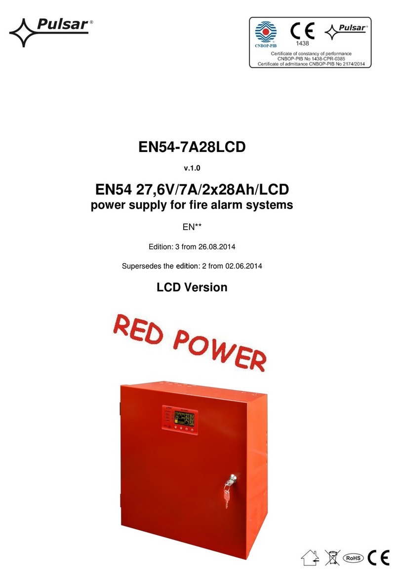
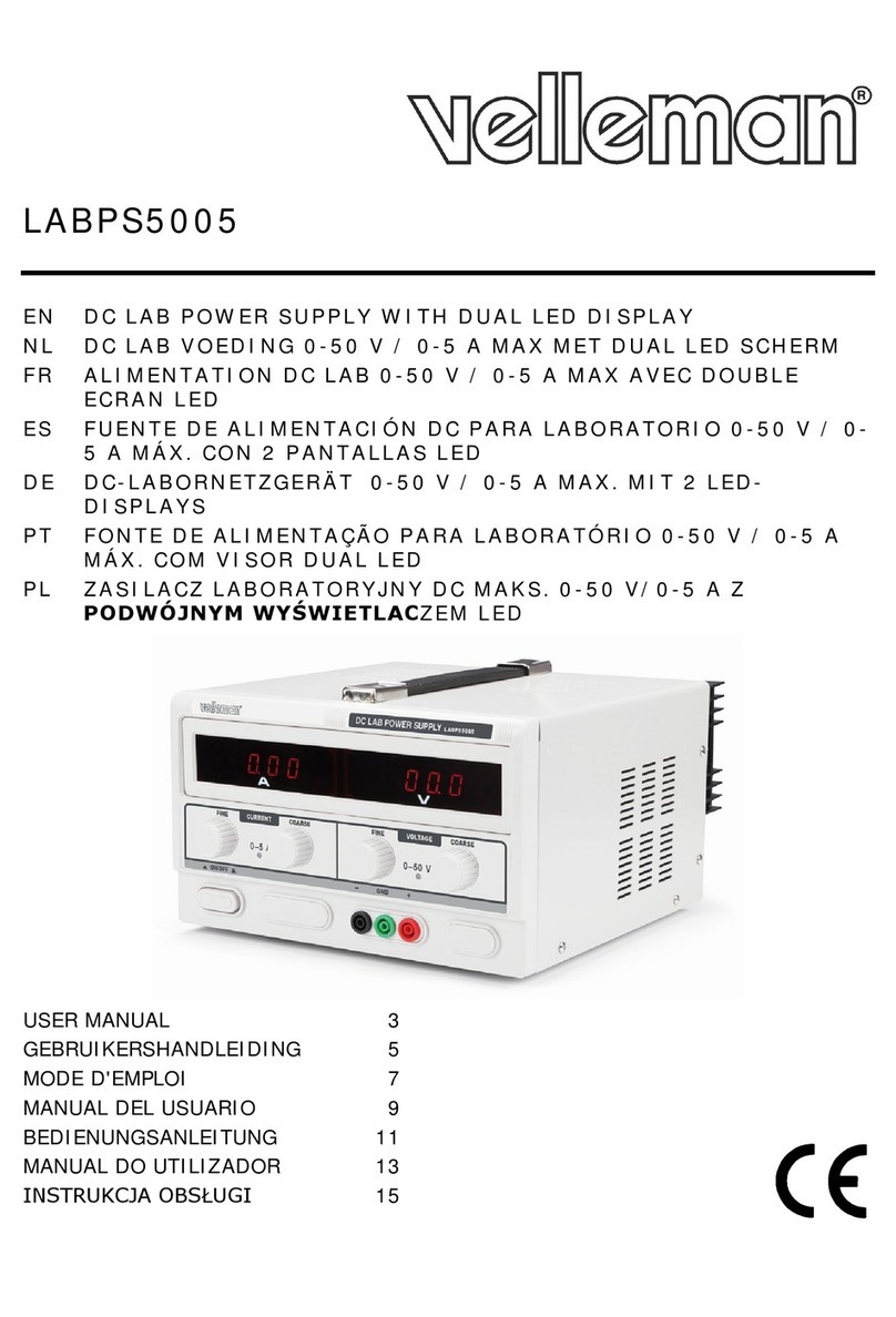
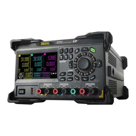
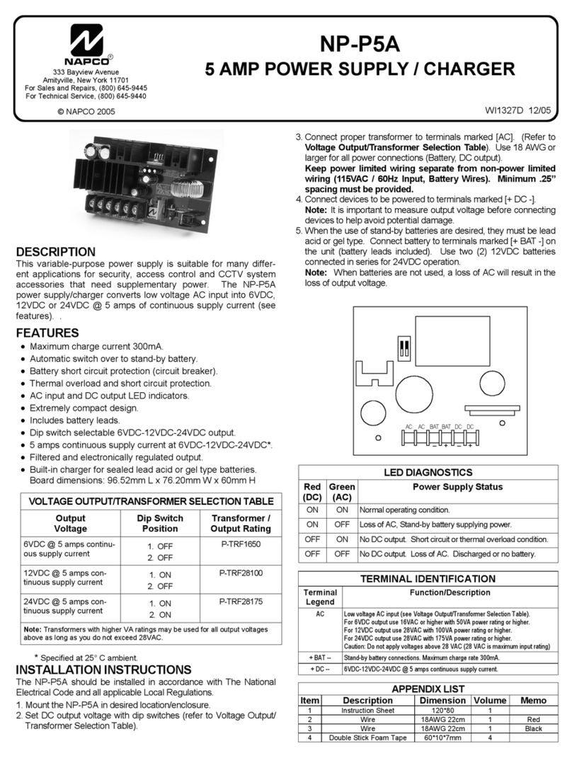
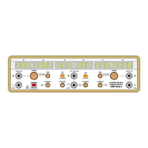
Everfine WY Series User manual

WY SERIES
DIGITAL CC& CV DC POWER SUPPLY
USER S MANUAL
V4.02
WY305
WY605
WY3010
WY5015
EVERFINE PHOTO-E-INFO CO., LTD.
ADD:Bldg.1 #669Binkang Rd.,Binjiang Hi-Tech
Zone, Hangzhou(310053), China
Tel :86-571-86698333
Fax :86-571-86696433
E-mail:Sales@everfine.cn
Service@everfine.cn
http://www.everfine.cn
Copyright EVERFINE, Copy or spread without authorization isprohibited.

WYSeries User s Manual
Copyright EVERFINE, Copy or spread without authorization isprohibited. 1
Foreword
Thank you for purchasingthe EVERFINE WY Series Digital Constant Current
&Constant Voltage DC PowerSupply. This user smanual containsuseful
information involving theinstrument sfunctions and operatingproceduresas well as
precautions that should be noticed during operation. In order touse the instrument
correctly,please read themanual carefully first,then putitin arightplace for quick
references.
Notes:
lEVERFINE pursues acontinuing improvementof the performance and functions
of its products, therefore, the contents of thismanual maybe changedwithout
prior notice.
lGreat effort has been made in preparation of this manual to ensure the accuracy of
its contents. However,if you have any questions or find any errors, pleasecontact
your dealer or EVERFINE sales office.
lCopying thecontents of this manual, the whole or part,without thewritten
permission of the EVERFINE is strictly prohibited.
lIf you have different understanding to this manual, please refer to the Technical
Service Department of EVERFINE.
Checking packagecontents
Please checkthe instrument carefully when you unpack the box for the first time.
If the instrument and related accessoriesare missing or appear abnormal, please
contact the dealer immediately

WYSeries User s Manual
Copyright EVERFINE, Copy or spread without authorization isprohibited.
2
Copyright Statement
The copyright of thismanual and the related information belong to
EVERFINE, and it isprotectedby the copyright lawof Peoples Republicof
China andotherrelevant international treaties. Copying, modifying,spreading,
excerpting, backing up ortranslating the whole orpart contents of this manual
by any company orpersonnel without the written permission of EVERFINE is
prohibited. Otherwiseit will betreated asinfringementand the infringerwill
assume lawresponsibility and all loss of EVERFINE.Anyinfringement related
above can be traced back to the responsible userby the unique product number
printed in the manual.
If EVERFINE hassigned awritten agreement with userandthe contents in
the agreement arein conflict with above terms, the contents in the written
agreement have preferential force effect.

WYSeries User s Manual
Copyright EVERFINE, Copy or spread without authorization isprohibited. 3
Precautions
1. Before using the instrument for the first time, make sureyou have read the
manual to avoid error operations.
2. It is prohibited strictly toreplace the fuse when the power is ON.
3. When connecting with the load, please pay attention to thepolarity ofbinding
posts of the power supply.When using the remote sampling function, please pay
close attention to thepolarity of the external sampling bindingposts
“S+”and“S-”.
4. Cut off the output before cutting off the load or turning off the instrument.
5. It isnormal that the instrument will emit heat inthe usage progress to make the
temperatureof externalsurfacehigh. Itisrequiredto keepgood air ventilation
and heat dispersion. Otherwise, it may decrease the instrument s life or damage it.
6. To ensure good air ventilation and heat dispersion capability,please don tblock
the vent holes in the rear panel and do not coverthe instrument.
7. When the remote sampling function is not used, please putthesampling selection
switch on the front panel at “IN”position to ensure the measuring accuracyofthe
voltage.
8. Please presetthe allowable peak value of voltage (protect voltage value)of the
load correctly to avoid damage of the load.
9. The instrument can work as the power isturned ON. For anaccurate
measurement, a warm-up time of more than 30 minutes is required.
10. The intervalof turningoffand onthe instrument should be no lessthan 3
minutes.
11. The power supply must be groundedwell and securely.
12. When used as the constant voltage power supply,please preset the Protect Voltage
value, then set proper values for currentand voltage,pressthe outputbutton to
exportpower,andthenrotatetheadjustingknob for voltageand currentto adjust
the outputfor CVstate.When the voltagevalue can tbeincreasedanymore,

WYSeries User s Manual
Copyright EVERFINE, Copy or spread without authorization isprohibited.
4
please checkif the output current or voltage exceeds theoutput range of the
instrument. If not, checkwhether the instrument is in thecurrent-limiting state
(check the indicatorfor CC ). If the indicator forCC is lit, theinstrument is in the
current-limiting state. Please turn the adjustingknob for currentclockwise to
increase thelimited current value tomake the instrument enter into theconstant
voltagestateagain (thenthe indicator for CVis litand theindicatorfor CC is
off).
13. When used as constantcurrentpower supply,preset the Protect Voltagevalue,
then setaproper valueof voltage and current, press the output button toexport
power,and then rotate the adjustingknob for voltage and current to adjust the
output for CCstate. When the current value cannot be increased anymore, please
check the output currentor voltage to see whether itexceeds the outputrange of
the instrument. If not, check whether theinstrument is inthe voltage-limiting
state(checkthe indicator for CV).If the indicator for CVis lit, it indicates that
the instrument is in thevoltage-limiting state. Please turn theadjusting knob for
voltage clockwise to increase the limited voltage value to make the instrument
enter into theconstant current stateagain (then the indicator for CCis litand the
indicator forCVis off).

WYSeries User s Manual
Copyright EVERFINE, Copy or spread without authorization isprohibited. 5
Contents
Foreword........................................................................................................................1
Copyright Statement ......................................................................................................2
Precautions.....................................................................................................................3
Contents.........................................................................................................................5
Chapter 1 Overviews......................................................................................................6
Chapter 2 Basic Principle...............................................................................................7
Chapter 3 Specifications................................................................................................8
3.1 Main specifications...........................................................................................8
Chapter 4 Panel Instructions........................................................................................11
4.1 Front Panel......................................................................................................11
4.2 Rear Panel.......................................................................................................15
Chapter 5 Operation Procedures..................................................................................16
5.1 Preparations.....................................................................................................16
5.2 Turn the power on...........................................................................................16
5.3 Adjustment......................................................................................................16
5.4 Switch load......................................................................................................18
5.5 Turn the power off...........................................................................................18
Chapter 6 Communication Interface............................................................................19
Chapter 7 Verification and Calibration ........................................................................23
7.1 Verification conditions....................................................................................23
7.2 The required equipment..................................................................................23
7.3 Verification Items............................................................................................23

WYSeries User s Manual
Copyright EVERFINE, Copy or spread without authorization isprohibited.
6
Chapter1Overviews
WYSeriesDigital Constant Current &Constant Voltage DC Power Supply
includesthe following types: WY305,WY605, WY3010 and WY5015, please refer to
chapter3for detailed specifications.WY series power supplyhave many advantages
such as wellintelligence, high stability and accuracy,easyto operate,adjustable
output current and voltage .etc. Theinstrument integratestheelectrical power meter
inside, and can monitor the currentand voltage accurately.Itis an idealpower supply
for standard light sources and so on.
The power supply has the following characteristics:
1Adopt numerical-control(NC) adjustment with threeadjusting levels:
COARE, MIDDLE and FINE which has good reliability, convenient adjustment and
long working life compared with mechanical coder.
2It also has the key-locking and one-key resettingfunction which can simplify
the operations.
3.Has over-voltage, over-current, over-temperature and alarm protection which
can ensure the safety of power supply and load.
4RS232 communication interface realizes remote control and data review.
5Good stability and high accuracy of output voltage/current.
6Automatic switch between Constant Current (CC) and Constant Voltage (CV)
states with relevant indicator.
7Remote sampling function with voltage drop compensating on the circuit can
ensure the accuracy of load voltage.

WYSeries User s Manual
Copyright EVERFINE, Copy or spread without authorization isprohibited. 7
Chapter2 BasicPrinciple
The principle schematicdiagram of WYSeries DigitalConstant Current&
Constant Voltage DC Power Supply is shown as follows:
AC/DCconversion High-power regulator
Error correctionnetwork
Sampling and
filter for current
Analysis test for
electrical
quantities
CPU
Keys
LED display
RS232
communication
DC outputPower supply
Fig.2.1 Principle schematicdiagramof WY series
The power source supplies electric energy to the high-power regulator via AC/DC
conversion.The power supply can switch thestatebetweenConstant Current (CC)
and Constant Voltage (CV) automatically with relevant indicatorso asto get high
reliability.
When the instrument works in the “CONSTANT VOLTAGE”state, the “Error
Correction Network”receivesand amplifies theerrorsignalsof electric bridge output.
And then, the amplified error signals control the high-power regulator to outputthe
preset voltage stably and light the indicator “CV”.
When the instrument works in the “CONSTANT CURRENT”state, the “Error
-Correction Network”compares thepreset standard voltage with the voltage drop of
the sampling resistance,and then amplifies the error signal, the amplified error signals
controlthehigh-power regulator tooutput thepresetcurrent stably, and lightthe
indicator “CC”.
The powersupply is equipped with silicon controlledroutineto controlthe
voltage dropof the high-power regulatorso as to ensure the high efficiency of the
power supply.

WYSeries User s Manual
Copyright EVERFINE, Copy or spread without authorization isprohibited.
8
Chapter3 Specifications
3.1 Main specifications
1CV source effect (line regulation): ≤5×10 5−rdg+2mV;
2CV load effect (load regulation): ≤5×10 5−rdg +2mV;
3CC source effect (line regulation): ≤1×10 4−rdg +0.5mA;
4CC load effect (line regulation): ≤1×10 4−rdg +1.5mA;
5.Output voltage drift under full range state:
±0.01%rdg/30mins (preheat 10mins after arriving in full range state);
6.Output current drift under full range state:
±0.01%rdg/30mins (preheat 10mins after arriving in full range state);
7Range of voltmeter: 5V/10V/25V/50V;WY605(5V/10V/25V/60V);
8Voltmeter resolution: 0.0001V(0.0000V~50.0000V);
9.Voltmeter accuracy: Class 0.05: ±(0.03%rdg +0.02%rg+1digits)
Class 0.02: ±(0.01%rdg +0.01%rg+2digits);
10 Output voltage accuracy: ±(0.05%rdg+2mV);
11 CV voltage ripple (Vrms): as shown in Table 1;
12 CC current ripple (Irms):as shown inTable 1;
13 Ammeter measuring range: as shown in Table 1;
14 Ammeter resolution: 0.00001A (0.00000A~10.0000A)
0.0001A(10.0000A~15.0000A);
15.Ammeter accuracy: Class 0.05: ±(0.03%rdg +0.02%rg+1digits)
Class 0.02: ±(0.01%rdg +0.01%rg+2digits);
16 Output current accuracy: ±(0.05%rdg + 0.2mA);
17 Max output ability: as shown in Table 1.

WYSeries User s Manual
Copyright EVERFINE, Copy or spread without authorization isprohibited. 9
Table 1 Specification parameters of WY series power supply
Model
Items WY305 WY605 WY3010 WY5015
CV voltage ripple
(Vrms) 0.5mV 0.5mV 0.5mV 1.5mV
CC currentripple
(Irms) 0.5mA 0.5mA 1.5mA 3.0mA
Ammeter
measuring range 0.5A/1A/2.5A/5A
0.5A/1A/2.5A/5A
1A/2A/5A/10A
1.5A/3A/7.5A/15A
Max.output power
150VA 300VA 300VA 700VA
Max.output voltage
30V 60V 30V 50V
Max.output current
5A 5A 10A 15A
Conditions:
Ambient temperature: 23 ±2;
Power supply: 220V±5V, 50Hz±2Hz ;
Half an hour of preheating.

WYSeries User s Manual
Copyright EVERFINE, Copy or spread without authorization isprohibited.
10
3.2 General specifications
1Ambient temperature: 23 ±15 ;
2Relative humidity: 55%±20%;
3Power supply: 220V±22V;
4Frequency: 50Hz/60Hz;
5.No mechanical vibration and electromagneticto interfere with thetest
results;
6Dimension and weight: as shown in Table 2.
Table 2 Dimension and Weight
Model
Item WY305 WY605
WY3010
WY5015
Dimension
(W×H×D)432mm×145mm×433mm
425mm×145mm×550mm
Weight Approx15kg Approx
25kg
Approx
25kg
Approx
40kg

WYSeries User s Manual
Copyright EVERFINE, Copy or spread without authorization isprohibited. 11
Chapter4 Panel Instructions
4.1 Front Panel
Fig.4.1 Front Panel
○1. CURRENT A
The window "CURRENT A" willdisplay thesetting currentvaluewhen the
"DISPLAY SETTING" indicatorlights, otherwise itdisplaysthemeasured value.
The window will display"Error" when abnormal situation arises.
○2.VOLTAGEV
The window "VOLTAGE V" will display the setting voltage value when the
"DISPLAYSETTING" indicator lights, otherwise it displaysthe measured value.
The window will display "oV", "oT", "RVSF1", "RVSF2" or "MIX" toshow the
abnormal situations of over voltage, over temperature, sampling voltage lower than
-2V, more than 25mA current flowing remote sampling terminal and two or more
above situations arising simultaneously. (RVSF: Remote Voltage Sample Fail).
○3. “+”terminal for remote sampling (red).
○4. Selection switch for sampling (inside or outside).
Being pressed, the voltage measurement is in the inner sampling stateinside the
case; onthecontrary, the voltagemeasurementis in theremote sampling state.
Remote sampling function can compensate thevoltage dropon the circuit to ensure

WYSeries User s Manual
Copyright EVERFINE, Copy or spread without authorization isprohibited.
12
the accuracyof the load voltage.
○5. “-”terminal for remote sampling (black).
○6. Power switch (POWER).
○7. CURRENT ADJUST
Rotating theknob foradjusting the current,clockwisefor increasing, while
anti-clockwise for decreasing, the upper limit value is the allowablemaximum
output current and the lower limit value is 0A. When the current value exceeds the
limit value, the buzzerwill give analarm to prompt usertorotatetheadjusting
knob in reverse direction.
○8. VOLTAGE ADJUST
Rotating theknob for adjusting the voltage,clockwisefor increasing, while
anti-clockwise for decreasing, the upper limit value is the allowablemaximum
output current and the lower limit value is5V. When the voltagevalueexceedsthe
limit value, the buzzerwill give analarm to prompt usertorotatetheadjusting
knob in reverse direction.
○9. Selection keys for adjusting level (COARSE, MIDDLE, FINE)
Press the keyto select the needed adjusting levels of coarse, middle or fine with
corresponding indicator lighting.
COARSE state: thecurrent variationis approx. 0.03A and the voltage variation is
approx. 0.15V as thenumericalcontrolencoder is rotatedby a
degree.
MIDDLE state: the current variationis approx. 0.003A and the voltage
variationisapprox. 0.015V as theNumericalControlencoderis
rotated by a degree.
FINE state:the currentvariation is approx. 0.16mA and thevoltage variation is
approx. 0.8mVas the Numerical Control encoder is rotated by a
degree.
○10. Local control: REMOTE
As the instrument communicateswith PC, theindicator “REMOTE”willlight
and the keyboard will bein hold state. Press thekey againto release the hold

WYSeries User s Manual
Copyright EVERFINE, Copy or spread without authorization isprohibited. 13
state.
○11. DISPLAY OVP
It can switch the voltagewindow by pressing the key. When the “DISPLAY
OVP”lights,voltage window will display the ProtectVoltage value flickeringly.
Adjusting theknob of Voltagecan change theover-protectedvoltagevalue. Press
the key againto complete the setup and the indicator of “DISPLAY OVP”will be
off. The lower limit of Protect Voltage is 5V.
○12. DISPLAY SETTING
It can switch the display between voltageand current. When the “DISPLAY
SETTING”lights, windows of Voltage and Current willdisplay the setting value.
Adjust the knob of Voltage and Current to change the settingvalue. Press the key
again tocomplete thesetup. PressOUTPUT key to displaythe settingvoltageand
current value.
○13. OUTPUT
Press thekey to output voltage with the indicator “OUTPUT”lighting.
○14. RESET
When the indicator “OUTPUT”lights, pressing thekey can make the power
supply output off and the voltage and current setting valuebe zero. When the
indicator “DISPLAY SETTING”lights, pressingthe key can make the voltage
and current setting valuebe zero. Inthe alarm state, pressthe key to stop the
alarm.
○15. KEY LOCK
Press thekeyto enterlock state and other keyswill be noneffective. At the same
time, the indicator “LOCK”will light. Pressingthe keyagain canrelease lock
state.
○16. “+”Outputterminal of power supply (OUTPUT+).
○17. “-”Output terminal of power supply (OUTPUT-).
○18. ALARM
When the four abnormities as below appear, the indicator ALARM will lightand
the buzzergives an alarm, also Current Window displays “Error”.At the same

WYSeries User s Manual
Copyright EVERFINE, Copy or spread without authorization isprohibited.
14
time, the currentoutputand voltage output dropto zero.Pressing “RESET”key
can stop the alarm except the second state.
(1) Voltage Window displays “oV”:it willalarmwhen theoutput voltage exceeds
93%~105% of protectingvoltagewhich issetbyuser,please checkthesetupor
wire connections.
(2) Voltage Windowdisplays “oT”:when the power supply output heavycurrentand
high power for along timeso as to cause high temperature of power tube inside
the case. Theinstrumentwill alarm when the temperature is over heated. Only
when the temperature falls to normal state can we operate thepower again.
(3) VoltageWindowdisplays “RVSF1”:the instrument will give RVSF1alarm as the
sampled voltage is less than -2V, please check the connection. For instance, in
exterior sampling state, reverses the polarity of the four-terminal connection.
(4) VoltageWindow displays “RVSF2”:the instrument will give RVSF2 alarmas
currentisover 25mA between terminals of exteriorsampling, pleasecheck the
connection. For instance, in interior sampling state, the load issupplied byexterior
sampling terminals.
(5) Voltage window displays "MIX": theinstrument will give MIX alarmas the two
or more abnormities above appear, please check setup and wire connections.
○19. The indicator for constant current working state: CC
As the power supply is in the “CC”or “currentlimiting”state, the indicator will
light.
○20. The indicator for constant voltage working state: CV
As the power supply is inthe “CV”or “voltage limiting”state, the indicator will
light.

WYSeries User s Manual
Copyright EVERFINE, Copy or spread without authorization isprohibited. 15
4.2 Rear Panel
Fig.4.2 RearPanel of WY305
Fig.4.3RearPanel of WY605/WY3010/WY5015
○1. Fan
○2. Fuse holder
○3. Power socket
○4. Grounding terminal
○5. “+”outputterminal of power supply (red)
○6. “-”output terminal of power supply(black)
○7. Communication Interface
○8. Nameplate
○9. Eight-pin navigate socket, matching with the LED clamp, provides power for
LED.

WYSeries User s Manual
Copyright EVERFINE, Copy or spread without authorization isprohibited.
16
Chapter5Operation Procedures
5.1 Preparations
(1) Connect the power cord and ensure the instrument is well grounded.
(2) The ratedvoltage ofthe instrument is 220V±22V, and ensure thepower supply
for the instrument is in the range.
5.2 Turn the power on
The instrument enters the initialstate atfirst. Please connect theload(the red
terminal is the “+”of power outputand the black terminal is the “-”of power
output). Theconnectingwires for power output should have good insulation
performance and havelower current density(≤4A/ mm2). Preheat for 30
minutes. .
5.3 Adjustment
(1). The default load protection voltage of WY305&WY3010is 30V and that of
WY605and WY5015 is 60V and50Vrespectively. If needs to change, firstly set
the protectionvoltage according to the load characteristics. Ifthe load is damaged
when the voltage exceeds10V, press “DISPLAY OVP”key to make the indicator
light on, andadjust the voltage knob to set theprotectionvoltage be 10V, and
then press “DISPLAY OVP”key again to make the indicator light off.
(2). The instrument is used as constant voltage power supply(Open-circuit):
In "DISPLAY SETTING" lighting state, setthevoltage andcurrentvalue firstly,
and press theOUTPUTkey, and thenthe indicator of OUTPUT lights, windows
of VOLTAGE and CURRENTdisplay the measured value. Adjust theknob for
voltage to the requiredvalue. Theconstantvoltage valueis displayedin the
Voltage window and theoutputcurrentvalue(I0=U0/RL)is displayedin the
currentwindow. When the indicator CV extinguishes and theindicator CC lights
up, the instrument entersinto the current limitingstate. As increasing thelimited

WYSeries User s Manual
Copyright EVERFINE, Copy or spread without authorization isprohibited. 17
currentvalueby turningthe adjustingknob for current clockwise, the instrument
will turn into the constant voltage state, simultaneouslythe indicator CC
extinguishesand the indicator CV lights up.
(3). The instrument is used as constant current power supply (Short-circuit):
In "DISPLAY SETTING" lighting state, firstly set thevoltage and current value,
and press OUTPUT key,and then the indicatorof OUTPUTlights, windows of
VOLTAGEand CURRENT displaythe measured value.Adjust the knob for
currenttothe requiredvalue.Theconstantcurrentvalue is displayedin the
currentwindow and the output voltage value (U0= I0×RL) is displayed in the
voltage window. When the indicator CC goes outand the indicatorCV lights up,
the instrument enters thevoltage limiting state. As increasingthe limitedvoltage
value by turning the adjusting knobfor voltage clockwise, the instrument will
turn into the constantcurrentstate, simultaneously the indicator CV goesout and
the indicator for CC lights up.
(4). When the output current is heavy, the instrument introduces the remote
sampling function to compensate thevoltage drop for the circuitryand measure
the voltageof the load accurately.When using thisfunction, placetheselection
switch for sampling in the front panel to the "OUTSIDE"position, and then
connect thepositiveterminal of loadwith the red terminal"S+" in the front panel
and connectthe negativeterminal of load withthe blackterminal "S-". Itis
strictly prohibited to connect the terminals reversely.
Notes:
1. Before cutting off the load, be sure to cut off the source output, and then
disconnectthe connection wires between the two terminalsofload and the
terminals S+”, S-”.
2. To ensure the measurement accuracy of voltage, please put the selection
switch for sampling at the INSIDE”position in the frontpanel whenthe remote
sampling function is not applied.

WYSeries User s Manual
Copyright EVERFINE, Copy or spread without authorization isprohibited.
18
Fig 5.1 Connections for remote sampling
5.4 Switch load
(1). Beforecutting off the load,cutoff the source outputand make sure there is no
voltage between the load.
(2). Removethe previous load and install the new load.
5.5 Turn the power off
(1). Please cut off the source output.
(2). Press POWER switch to turn off the power.

WYSeries User s Manual
Copyright EVERFINE, Copy or spread without authorization isprohibited. 19
Chapter6 Communication Interface
The instrument isequipped with RS-232-C interface torealizeremotecontrol.
The detail operation of serial interface is described as below.
The instrument adopts half-duplexasynchronous communication method to
communicate with one PC or severalPCs. The 9 female pins are defined asfollows:
2 :TXD (Transmit data to PC)
3 :RXD (Receive data from PC)
7 :GND (Referenced-grounding)
Other pins are hanging.
The serial port works in mode 2(9-bit communication method): a frame of 11bits,
the 0stis the startbit, the following 8bitsare the data-bits, the9th isthe
programmable bit and the last one is the stop bit. The baud- rate is2400Bps. The
address codeof the instrument isfixed and it isdisplayed when turning on the
instrument.(Take theWY305 for example when turning on the WY305,
numericalpipes light→numerical pipesgo out→"EVERFINE"→"WY305
V1.01"→"Addr 040"which is the addresscode ofthe instrument). The
communication contentis the commandwords and settingdata expressed as ASCII
code. The measurementresultsexpressedby 16-byte ASCII codeincluding 14 bytes
for measurement results and 2 bytes for unit display word.
The receiveddata are ASCII codes, and the format andmeaning are shown as
follows:
This manual suits for next models
4
Table of contents
