Comelit EN54C Series User manual

USER MANUAL
EN
Edition: 5 from 21.12.2022
Supersedes edition: 4 from 08.07.2021
Power supplies
EN54C series
v.1.1
Power supplies for fire alarm systems and
smoke and heat control systems.

2
GENERAL SAFETY RULES
Before installation, read the instruction manual to avoid errors that
can damage the device and give you an electric shock.
Before installation, cut off the voltage in the 230 V power-supply circuit.
To switch power off, use an external switch, in which the distance between the
contacts of all poles in the disconnection state is not less than 3 mm.
The shock protection circuit shall be done with a particular care: the yellow and green
wire coat of the power cable should be connected to the terminal marked with
the grounding symbol on the PSU enclosure. Operation of the PSU without the
properly made and fully operational shock protection circuit is UNACCEPTABLE! It
can cause damage to the equipment or an electric shock.
The device should be transported without batteries. This has a direct impact on the
safety of the user and the device.
Installing and connecting the power supply must be carried out without batteries.
When connecting batteries to the power supply, pay particular attention to the correct
polarity. If necessary, it is possible to permanently disconnect the battery from the
power supply systems by removing the FBAT fuse.
The power supply is adapted to be connected to a power distribution network with an
effectively earthed neutral conductor.
Ensure a free, convection air flow around the enclosure. Do not cover the ventilation
openings.

3
TABLE OF CONTENTS
1. PSU FEATURES.....................................................................................................................................4
2. FUNCTIONAL REQUIREMENTS OF THE PSU.............................................................................4
3. TECHNICAL DESCRIPTION..............................................................................................................5
3.1. GENERAL DESCRIPTION........................................................................................................................................................5
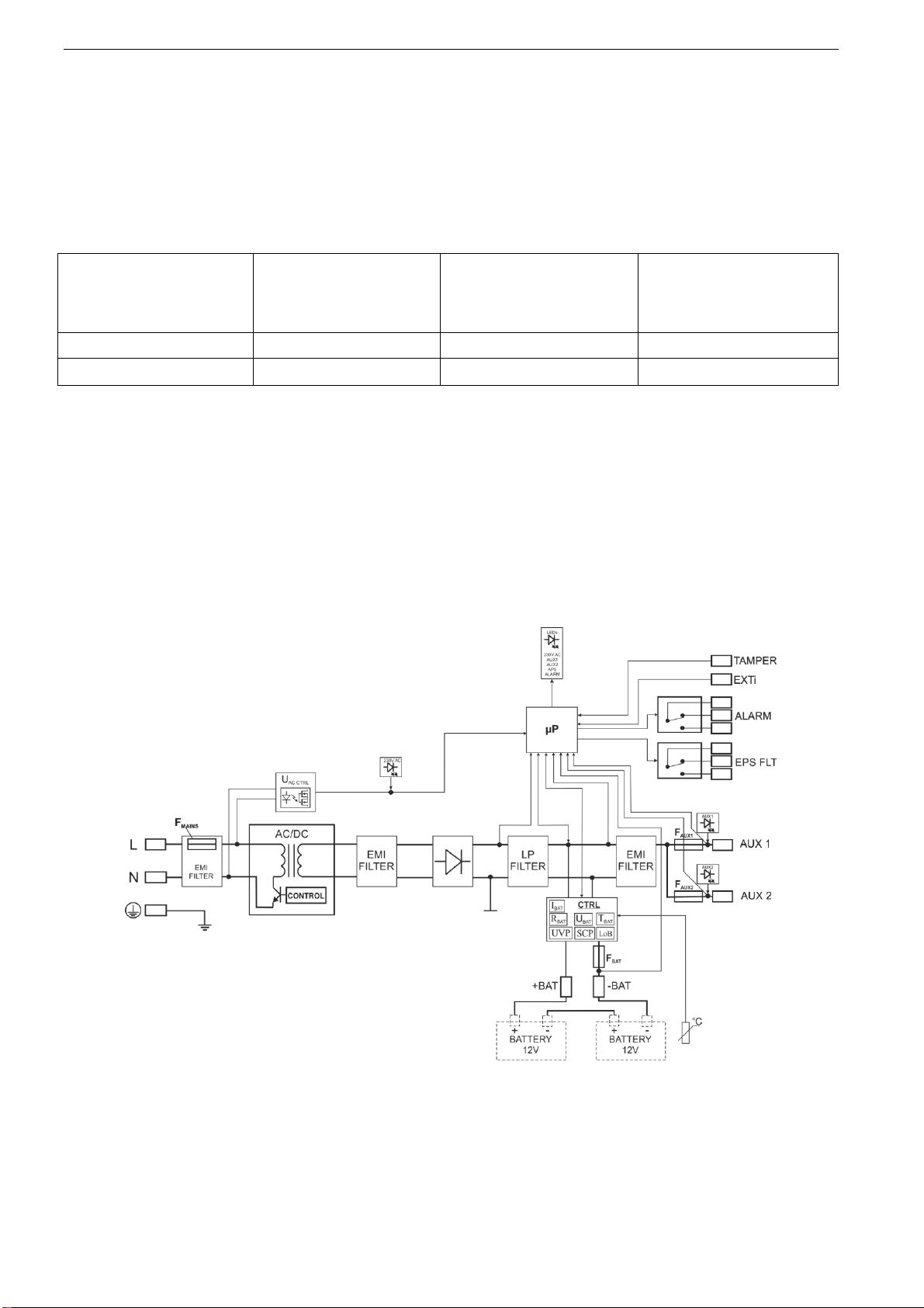
3.2. BLOCK DIAGRAM.................................................................................................................................................................5
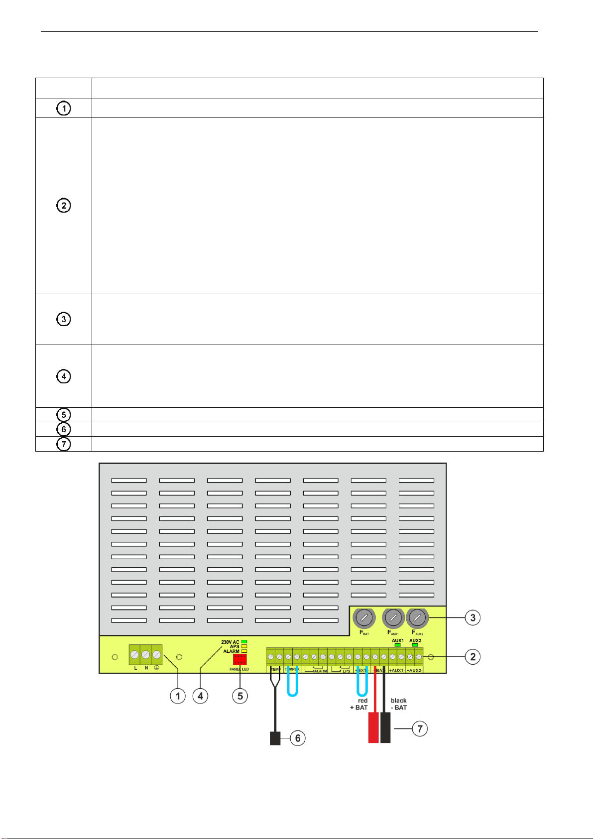
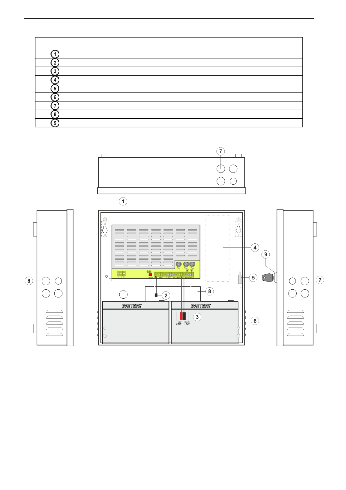
3.3. DESCRIPTION OF COMPONENTS AND POWER SUPPLY TERMINALS.........................................................................................6
4. INSTALLATION....................................................................................................................................8
4.1. REQUIREMENTS...................................................................................................................................................................8
4.2. INSTALLATION PROCEDURE. ................................................................................................................................................9
4.3. PROCEDURE FOR CHECKING THE POWER SUPPLY AT THE PLACE OF INSTALLATION............................................................10
5. FUNCTIONS.........................................................................................................................................11
5.1. CONTROL PANEL................................................................................................................................................................11
5.2. TECHNICAL OUTPUTS.........................................................................................................................................................12
5.3. INPUT OF COLLECTIVE FAILURE:EXTI...............................................................................................................................13
5.4. INDICATION OF THE ENCLOSURE OPENING -TAMPER. .....................................................................................................13
5.5. PSU OVERLOAD.................................................................................................................................................................13
5.6. SHORT-CIRCUIT OF THE PSU OUTPUT. ...............................................................................................................................13
6. RESERVE POWER SUPPLY CIRCUIT...........................................................................................14
6.1. BATTERY DETECTION. .......................................................................................................................................................14
6.2. PROTECTION AGAINST SHORT-CIRCUIT OF THE BATTERY TERMINALS................................................................................14
6.3. PROTECTION AGAINST REVERSE BATTERY CONNECTION....................................................................................................14
6.4. DEEP DISCHARGE BATTERY PROTECTION UVP. .................................................................................................................14
6.5. BATTERY TEST...................................................................................................................................................................14
6.6. MEASUREMENT OF THE RESISTANCE OF THE BATTERY CIRCUIT.........................................................................................14
6.7. BATTERY TEMPERATURE MEASUREMENT. .........................................................................................................................14
6.8. STANDBY TIME. .................................................................................................................................................................15
7. TECHNICAL PARAMETERS. ..........................................................................................................16
Table 5. Electrical parameters.............................................................................................................................................16
Table 6. Mechanical parameters..........................................................................................................................................18
Table 7. Safety of use............................................................................................................................................................18
Table 8. Operation parameters. ...........................................................................................................................................18
Table 9. Recommended types and sections of installation cables. .......................................................................................18
8. TECHNICAL INSPECTIONS AND MAINTENANCE...................................................................19

4
1. PSU features.
Compliant with the requirements of the
EN 54-4:1997+AC:1999+A1:2002+A2:2006,
EN 12101-10:2005+AC:2007
27,6 V DC uninterruptible power supply
available versions with 2 A / 5 A current
efficiencies
available versions with space for 7 Ah –65 Ah
batteries
independently protected outputs AUX1 and AUX2
high efficiency (up to 89%)
low level of voltage ripple
microprocessor-based automation system
measurement of the resistance of the battery
circuit
automatic temperature-compensated charging
automatic battery test
two-stage battery charging process
accelerated battery charging
monitoring of the continuity of the battery circuit
monitoring of the battery voltage
monitoring of charging and maintenance of the
batteries
deep discharge battery protection (UVP)
battery overcharge protection
the LoB low battery voltage indication
battery output protection against short-circuit
and reverse connection
output voltage control
fuse monitoring of AUX1 and AUX2 outputs
relay output of collective failure ALARM
EPS relay output indicating 230 V power loss
the EXTi input of external failure
protections:
SCP short-circuit protection
OLP overload protection
OVP overvoltage protection
Surge protection
Antisabotage protection –Tamper
closing the enclosure –lock
optical indication –LED panel
2. Functional requirements of the PSU.
The buffer power supplies for fire alarm systems has been designed in accordance with the following
standards:
- EN 54-4:1997+AC:1999+A1:2002+A2:2006 Fire detection and fire alarm systems
- EN 12101-10:2005+AC:2007 Smoke and heat control systems
Functional requirements
Requirements
according to
standards
Power supplies
EN54C series
Two independent power sources
YES
YES
EPS network failure indication
YES
YES
Two independent power supply outputs protected against short
circuits
YES
YES
Temperature compensation of the battery charging voltage
YES
YES
Measurement of the resistance of the battery circuit
YES
YES
LoB low battery voltage indication
YES
YES
Recharging battery to 80% of rated capacity within 24 hours
YES
YES
Protection against deep battery discharge
YES
YES
Protection against short-circuit at the battery terminals
YES
YES
Charging circuit failure Indication
YES
YES
Short-circuit protection
YES
YES
Overload protection
YES
YES
Output of collective failure ALARM
YES
YES
EPS technical output
YES
YES
Low output voltage indication
-
YES
High output voltage indication
-
YES
Power supply failure indication
-
YES
Protection against surges
-
YES
Input of external failure indication EXTi
-
YES
Tamper switch unwanted enclosure opening
-
YES

5
3. Technical description.
3.1. General description.
The buffer power supplies has been designed for an uninterrupted supply of fire alarm systems, smoke
and heat control systems, fire protection equipment and fire automatics requiring stabilized voltage of 24 V DC
(±15%). The power supplies are fitted with two independently protected AUX1 and AUX2 outputs, which provide
a voltage of 27,6 V DC and the total current efficiency depending on the version:
Power supply model
Battery
Continuous operation
Imax a
Instantaneous
operation
Imax b
EN54C-2A17
17 / 18 Ah
1,2 A
2 A
EN54C-5A17
17 / 18 Ah
4,2 A
5 A
In case of power loss, the PSU switches to battery power, providing uninterruptible power supply.
The power supply unit is housed in a metal enclosure (color red RAL 3001) with space for battery.
Power supply units works with maintenance-free lead acid batteries made with AGM technology or gel
technology.
3.2. Block diagram.
Power supplies has been manufactured based on a high-efficiency system of AC/DC converter.
Applied microprocessor circuit is responsible for the full diagnostics of the PSU parameters and batteries.
Figure below shows a flowchart of the power supply, along with selected functional blocks which are
essential for the proper functioning of the unit.
Fig. 1. PSU block diagram.

6
3.3. Description of components and power supply terminals.
Table 1. Elements of the PSU (Fig. 2).
Compone
nt No.
Description
230 V supply connector with a terminal for connection of a protective conductor
Terminals:
TEMP –input of the battery temperature sensor
TAMPER –input of the microswitch tamper
Closed input = no indication
Open input = alarm
ALARM –technical output of collective failure of the PSU - relay type
EPS –technical output of AC power failure indication
open = AC power failure
closed = AC power - O.K.
EXTi –external failure input
Closed input = no indication
Open input = alarm
+BAT- –terminals for connecting the battery
+AUX1- –AUX1 power output ( - AUX=GND)
+AUX2- –AUX2 power output ( - AUX=GND)
CAUTION! In Fig.2 the set of contacts shows a potential-free status of the relay, which corresponds to power
supply failure.
Fuses:
FBAT –fuse in the battery circuit,
FAUX1 –fuse in the AUX1 output circuit,
FAUX2 –fuse in the AUX2 output circuit,
The fuse values are given in table 4 –„Electrical parameters”.
LEDs –optical indication:
230 V AC –voltage in 230 V AC circuit
APS –battery failure
ALARM –collective failure
AUX1 –AUX1 output voltage (at the AUX1 connector)
AUX2 –AUX2 output voltage (at the AUX2 connector)
PANEL LED –connector to the external LED indicators
Battery temperature sensor
Battery connectors; positive: +BAT = red, negative: - BAT = black
Fig. 2. View of power supply module based on EN54C-2A.

7
Table 2. Elements of the PSU (Fig. 3).
Component
No.
Description
PSU (Tab. 1, Fig. 2)
Battery temperature sensor
Battery connectors; positive: +BAT = red, negative: - BAT = black
A place for installation of additional modules
TAMPER; microswitch (contacts) of antisabotage protection (NC)
Fitting battery
Embossing for cable gland
Embossings for concealed wires
Lock
Fig. 3. View of power supply based on EN54C-2A.

8
4. Installation.
4.1. Requirements.
PSU is to be mounted by a qualified installer, holding relevant permits and licenses (applicable and
required for a given country) to connect (interfere) with ~230 V mains supply.
As the power supply is designed for a continuous operation and is not equipped with a power-
switch, therefore, an appropriate overload protection in the power supply circuit should be provided. Moreover,
the user should be informed how to disconnect the power supply unit from the mains supply (usually by
assigning an appropriate fuse in the fuse box). One switch should only protect one power supply. The electrical
system shall follow valid standards and regulations. The power supply should operate in a vertical position in
order to provide free and convectional air flow through ventilating holes of the casing.
As the PSU cyclically runs a periodic battery test, during which the resistance in the battery circuit is
measured, pay attention to the proper connection of cables to the terminals. Installation cables should be firmly
connected to the battery side terminals and to the power supply connector. If necessary, it is possible to
permanently disconnect the battery from the power supply systems by removing the FBAT fuse.
The side walls of the housing include the embossings, which should be used to carry out installation
cables. Use a blunt instrument to make an opening for cable gland from the outside of the housing.
Then, carefully mount the cable gland, protecting the PSU from water penetration, in the opening.
Fig. 4. The method of forming an opening for cable gland.
The PSU is fitted with PG9 and PG11 cable glands. Gland size should be chosen depending on the
cross-section of the cable. Single cable gland can be used for only one wire.
Fig. 5. Recommended types and sections of installation cables PG9 and PG11 for cable glands.

9
4.2. Installation procedure.
CAUTION!
Before installation, cut off the voltage in 230 V AC power-supply circuit.
To switch power off, use an external switch, in which distance between contacts of all poles in
disconnection state is not less than 3 mm.
It is required to install an installation switch with a nominal current of 6 A in the power supply circuits
outside the power supply unit.
1. Mount the PSU in a selected location with use of special metal expansion bolts. Do not use PVC
dowels.
2. Connect power cables ~230 V to L-N clips of PSU. Cable length inside housing should not exceed
10cm. Connect ground wire to terminal marked with grounding symbol in enclosure. Use a three-
core cable (with a yellow and green protection wire) to make connection. Wires should be deisolated to
a length of 7.2mm.
3.
Shock protection circuit shall be done with a particular care: yellow and green wire coat of power
cable should be connected to terminal marked with grounding symbol on PSU enclosure.
Operation of PSU without properly made and fully operational shock protection circuit is
UNACCEPTABLE! It can cause damage to equipment or an electric shock.
4. Connect the receivers’ cables to the AUX1 and AUX2 output terminals on the PSU board.
5. If needed, connect the cables from the devices to the technical inputs and outputs:
- ALARM; technical output of collective failure of the PSU
- EPS; technical output indication of 230 V power collapse
- EXTi; input of external failure
6. Install the batteries in a designated area of the enclosure (see Fig. 3).
Connect the batteries with the PSU paying special attention to the correct
polarity. Batteries must be connected in series using the special cable
(included). Attach the temperature sensor to any of the batteries with
mounting tape (included). Place the temperature sensor between the
batteries.
7. Switch on the ~230 V supply. The corresponding LEDs on the power supply PCB should be ON: 230 V
green and AUX1, AUX2.
8. Check the current consumption of the receivers, taking into account the battery charging current, so as
not to exceed the total current efficiency of the PSU (see section 3.1).
9. Once the tests are completed, close the enclosure.

10
4.3. Procedure for checking the power supply at the place of installation.
1. Check indication displayed on front panel of power supply unit:
a) 230 V AC LED should remain lit to indicate presence of mains supply voltage.
b) AUX LED should remain lit to indicate the presence of supply voltage.
2. Check the output voltage after 230 V power failure.
a) Simulate the lack of 230 V mains voltage by disconnecting main circuit breaker.
b) 230 V AC LED should go out.
c) AUX LED should remain lit to indicate the presence of output voltage.
d) LED ALARM LED will start blinking.
e) EPS and ALARM technical outputs will change status into opposite after 10 s.
f) Turn on 230 V mains voltage again. Indication should return to initial status from point 1 after a few
seconds.
3. Check whether lack of continuity in the battery circuit is properly indicated.
a) During normal PSU operation (230 V mains voltage on), disconnect battery circuit by disconnecting FBAT
fuse.
b) Within 5 minutes the PSU will start signaling a failure in the battery circuit.
c) ALARM LED will start blinking.
d) ALARM technical output will change status into opposite.
e) Turn on FBAT fuse in the battery circuit again.
f) Power supply should return to normal operation, indicating initial status, within 5 minutes after battery
test is completed.

11
5. Functions
5.1. Control Panel.
The PSU is equipped with a LED panel allowing checking the current status of the power supply.
Fig. 6. Control panel.
Table 3. The description of the buttons and LEDs of the LCD panel.
- green LED indicating 230 V voltage
- green LED AUX indicating power at the AUX1 and AUX2 output of the PSU
- yellow LED ALARM indicating collective failure
ALARM LED flashes specified number of times to indicate failure code according to table below.
If PSU has several failures at the same time, they are all indicated consecutively.
Table 4. Coding of PSU failure by number of ALARM LED flashes on PCB of PSU.
Failure description
Number of
flashes
F01 –No AC
1
F02 –AUX1 fuse is faulty
2
F04 –Output overload
3
F05 –Undercharged battery
4
F06 –High AUX1 voltage
5
F08 –Charging circuit failure
6
F09 –Low AUX1 voltage
7
F10 –Low battery voltage
8
F12 –External input EXT
9
F14 –Temp. sensor malfunction
10
F15 –High battery temperature
11
F16 –No battery
12
F17 –Battery fail
13
F18 –High resistance of battery circuit
14
F21 –PSU cover opened
15
F22 –AUX2 fuse is faulty
16
F26 –High AUX2 voltage
17
F29 –Low AUX2 voltage
18
F51 –Service code
19
F52 –Service code
20
F60 –Service code
21
F61, F64, F65, F69, F70, F71, F72, F73, F74 –Service code
22

12
5.2. Technical outputs.
The power supply is fitted with relay indication outputs changing state upon the occurrence of a specific
event.
Fig. 7. Electrical diagram of relay outputs.
EPS - output indicating 230 V power loss.
The output indicates 230 V power loss. Under normal status –with the 230 V supply on, the output
is closed. In case of power failure, the PSU will switch the output into the open position after a time 10 s.
Fig. 8. EPS technical output.
CAUTION! In Figure the set of contacts shows a potential-free status of the relay, which corresponds
to power supply failure.
ALARM - technical output of collective failure indication.
Output indicating collective failure. In the case of 230 V power failure, battery circuit failure, PSU
failure, or EXTi input activation, the collective failure signal ALARM will be generated.
Failure can be triggered by the following events:
- AC power loss
- faulty batteries
- undercharged batteries
- disconnected batteries
- high resistance of the battery circuit
- no continuity in the battery circuit
- UAUX1, AUX2 output voltage below 26 V
- UAUX1, AUX2 output voltage over 29,2 V
- battery charging circuit failure
- blown FAUX1 or FAUX2 fuse
- PSU overload
- to high battery temperature (>65°C)
- temperature sensor failure, t < -20°C or t > 80°C
- enclosure opening - TAMPER
- internal damage of the PSU
Fig. 9. Technical output ALARM.
CAUTION! In Fig.2 the set of contacts shows a potential-free status of the relay, which corresponds
to power supply failure.

13
5.3. Input of collective failure: EXTi.
The EXT IN (external input) technical input indicating collective failure is intended for additional, external
devices that generate the failure signal. Disconnection of the EXTi terminals will cause a failure of the PSU and
generate a failure signal at the ALARM output.
The EXTi technical input is not galvanically isolated from the power supply. The "minus" terminal is
connected to the power supply.
The connection of external devices to the EXT IN input is shown in the electrical diagram below. Relay
outputs or "open collector" signal outputs can be used as the signal source.
Fig. 10. Connections to the EXTi input.
5.4. Indication of the enclosure opening - TAMPER.
The PSU is fitted with the micro-switch tamper indicating enclosure opening.
The tamper cable is not connected to the terminal in the factory settings. In order to activate tamper,
remove the jumper from tamper terminal and plug in the tamper cable.
Each opening the enclosure will generate a failure signal at the ALARM technical output.
Fig. 12. TAMPER technical output.
5.5. PSU overload.
If the output overload occurs during the PSU operation, the PSU will limit the battery charging current for
1 minute. If, after this time, the overload is removed, the normal charging mode will be restored.
5.6. Short-circuit of the PSU output.
In case of short-circuit of the AUX1 or AUX2 output, one of the fuses - FAUX1 or FAUX2 –becomes
permanently blown. The restoration of the voltage at the output requires the replacement of the fuse.
During a short circuit, the PSU failure is indicated by the ALARM LED and a collective failure signal at the
ALARM output.

14
6. Reserve power supply circuit.
The PSU is fitted with intelligent circuits: battery charging circuit with the function of the accelerated
charging and battery control, which main task is to monitor the condition of the batteries and the connections in
the circuit.
If the controller detects a power failure in the battery circuit, appropriate indication and change of the
ALARM technical output.
6.1. Battery detection.
The control unit of the PSU checks the voltage at the battery terminals and, depending on the measured
values, determines the appropriate reaction:
UBAT below 4 V - batteries not connected to the PSU circuits
UBAT = 4 to 20 V - faulty batteries
UBAT over 20 V - batteries connected to the PSU circuits
6.2. Protection against short-circuit of the battery terminals.
The PSU is fitted with the circuit protecting against short-circuit of the battery terminals. In case of short
circuit, control circuit immediately disconnects the batteries from the rest of the power supply circuit, so the loss
of output voltage on power supply outputs is not observed. Automatic reconnection of the batteries to the PSU's
circuits is only possible after the removal of the short-circuit and correct connection of the circuits.
6.3. Protection against reverse battery connection.
The PSU is protected against reverse connection of the battery terminals. In case of incorrect
connection, the FBAT fuse in the battery circuit becomes blown. The return to normal operation is possible only
after replacing the fuse and correct connection of the batteries.
6.4. Deep discharge battery protection UVP.
The PSU is fitted with the disconnection system and the battery discharge indication. If the voltage at
the battery terminals drops below 20 V ± 0.2 V during battery-assisted operation, acoustic indication will be
activated and the batteries will be disconnected within 15s.
The batteries are reconnected to the power supply unit automatically once the 230 V mains supply is
restored.
6.5. Battery test.
The PSU runs battery test every 5 minutes. During testing, the control unit of the PSU measures the
electrical parameters according to the implemented measuring method.
A negative result occurs when the:
- battery circuit continuity is interrupted,
- resistance in the battery circuit increases above 300 mΩ
- terminal voltage drops below 24 V.
The battery test will also be automatically locked when the PSU is in the operating mode, in which the
battery test is impossible. Such condition occurs, for example, during battery assisted operation.
6.6. Measurement of the resistance of the battery circuit.
The PSU is checking the resistance in the battery circuit. During the measurement, the PSU driver takes
into account the key parameters in the circuit,and once the limit value of 300m ohms is exceeded, a failure is
indicated.
A failure may indicate considerable wear or loose cables connecting the batteries.
6.7. Battery temperature measurement.
Temperature measurement and compensation of the battery charging voltage can extend the life of the
batteries.
The PSU has a temperature sensor to monitor the temperature parameters of installed batteries. It is
recommended to place the temperature sensor between the batteries. Be careful not to damage the sensor
when moving the batteries.

15
Fig. 14. Mounting of the temperature sensor.
The nominal battery operating temperature recommended by many manufacturers is
25°C. Working at elevated temperatures will significantly shorten the battery lifetime. The service
life is reduced by half for each sustained temperature rise of 8°C above the nominal temperature.
This means that the battery lifespan, when operated at 33°C, can be decreased by 50%!
6.8. Standby time.
Battery-assisted operating depends on battery capacity, charging level and load current. To maintain an
appropriate standby time, current drawn from the PSU in battery mode should be limited.
Required, minimum battery capacity to work with the PSU can be calculated with the following formula:
QAKU = 1.25 ﴾﴾Id + Iz﴿•Td + ﴾Ia + Iz﴿•Ta + 0.05 Ic ﴿
Where: QAKU –The minimum battery capacity [Ah]
1.25 –the factor related to the decrease in battery capacity due to aging
Id –the current drawn by the load during inspection [A]
Iz –PSU current consumption (including optional modules) [A] (Table 12)
Td –required inspection time [h]
Ia –the current drawn by the load during an alarm [A]
Ta –alarm duration [h]
Ic –short-term output current

7. Technical parameters.
Electrical parameters (Table 5).
Mechanical parameters (Table 6).
Safety of use (Table 7).
Operation parameters (Table 8).
Recommended types and sections of installation cables (Table 9).
Table 5. Electrical parameters.
EN54C-2A17
EN54C-5A17
Functional class EN 12101-10:2005 +AC:2007
A
Mains supply
~230 V
Current consumption
0,58 A
1,38 A
Inrush current
40 A
50 A
Power frequency
50 Hz
Output power PSU
56,8 W
142 W
Efficiency
88%
87%
Output voltage at 20ºC
22 V –27,6 V DC –buffer operation
20 V –27,6 V DC –battery-assisted operation
Continuous output current Imax a
1,2 A
4,2 A
Instantaneous output current Imax b (5 min)
2 A
5 A
Recommended battery capacity
17 Ah
17 Ah
Minimum battery capacity
7 Ah
Maximum battery capacity
20 Ah
Battery charging current
0,8 A
Net/gross weight [kg]
4,1/4,4
4,9/5,2
Maximal resistance of the battery circuit
300 mΩ
Ripple voltage (max.)
50 mVp-p
150 mVp-p
Current consumption by the PSU
during battery-assisted operation
52 mA
55 mA
Coefficient of temperature compensation of the
battery voltage
-36 mV / ºC (-5oC ÷ +40oC)
LoB low battery voltage indication
Ubat < 23 V, during battery mode
Overvoltage protection OVP
U>32 V ± 2 V, automatic recovery
Short-circuit protection SCP
F4 A
F6,3 A
- FAUX1, FAUX2 melting fuse (failure requires fuse replacement)
Overload protection OLP
105 –150% of power supply, automatic recovery

17
Battery circuit protection SCP and reverse
polarity connection
F5 A
F10 A
- FBAT melting fuse (failure requires fuse replacement)
Deep discharge battery protection UVP
U<20 V (± 2%) –disconnection of the batteries
Tamper indicating enclosure opening
Micro-switch TAMPER
Technical outputs:
- EPS FLT; indicating AC power failure
- ALARM; indicating collective failure
- relay type: 1 A@ 30 V DC / 50 V AC
- 10s time lag.
- relay type: 1 A@ 30 V DC / 50 V AC
Technical inputs:
- EXTi; external failure input
- TAMPER; input of the microswitch tamper
Closed input –no indication
Open input –alarm
Closed input - no indication
Open input - alarm
Optical indication:
- LEDs on the PCB of the power supply unit (see section 3.3)
- LED panel:
~230 V mains power supply ON
DC power at the AUX outputs
failure indication
Fuses: - FBAT
- FAUX1
- FAUX2
F 5 A/250 V
F 4 A/250 V
F 4 A/250 V
F 10 A/250 V
F 6,3 A/250 V
F 6,3 A/250 V

18
Table 6. Mechanical parameters.
Battery space:
2x17/18 Ah
Enclosure dimensions
W=385, H=402, D+D1=88+8 W1=390, H1=406 [+/- 2mm]
Mounting (WxH)
358x325 xΦ6 x4szt [mm]
Fitting battery
(WxHxD) (max.)
2x17/18 Ah / 12 V (SLA)
375x180x80 [+/-2 mm] max
Enclosure
Steel plate DC01 1mm
color: RAL 3001 (red)
Closing
Key lock
Terminals
Battery outputs BAT: Ф6 (M6-0-2,5)
Mains supply: Ф0,41÷2,59 (AWG 26-10), 0,5÷4mm2
Outputs: Ф0,51÷2,05 (AWG 24-12), 0,5÷2,5mm2
Cable glands
PG9 –cable diameter Ф4÷8mm - PG11–cable diameter Ф5÷10mm
Notes
The enclosure does not adjoin the mounting surface so that cables can be led. Convection cooling.
Table 7. Safety of use.
Protection class EN 62368-1
I (first)
Protection grade EN 60529
IP30
Insulation electrical strength:
- between input (network) circuit and the output circuits of PSU
- between input circuit and protection circuit
- between output circuit and protection circuit
4000 V DC
2500 V DC
500 V DC
Insulation resistance:
- between input circuit and output or protection circuit
100 MΩ, 500 V DC
Table 8. Operation parameters.
Environmental class EN 12101-10:2005+AC:2007
1
Operating temperature
-5oC…+40oC
Storing temperature
-25ºC...+60ºC
Relative humidity
20%...90%, no condensation
Sinusoidal vibrations during operation:
10 ÷ 50 Hz
50 ÷ 150 Hz
0,1 G
0,5 G
Surges during operation
0,5 J
Direct insolation
unacceptable
Vibrations and surges during transport
According to PN-83/T-42106 standard
Table 9. Recommended types and sections of installation cables.
Mains supply ~230 V L-N-PE (Table1 [1])
HDGs 3 x 0,75 mm2…1,5 mm2
OMY 3 x 0,75 mm2…1,5 mm2
AUX1, AUX2 output terminals (Table 1 [2])
HLGs 2 x 1,5 mm2…2,5 mm2
Indication inputs/outputs (Table 1 [2])
YnTKSY 1 x 2 x 0,8 mm2

8. Technical inspections and maintenance.
Technical inspections and maintenance can be performed after disconnecting the power supply from the
power network. The PSU does not require any specific maintenance, however, its interior should be cleaned with
compressed air if it is used in dusty conditions. In case of fuse replacement, use only compatible replacement
parts. Technical inspections should be carried out not less frequently than once per year. During the inspection,
check the batteries and run the battery test. 4 weeks after installation, re-tighten all threaded connections, (see Fig.
2 [1,2]).
WEEE MARK
According to the EU WEE Directive –It is required not to dispose of electric or electronic waste as unsorted
municipal waste and to collect such WEEE separately.
CAUTION! The power supply unit is adapted for cooperation with the sealed lead-acid batteries (SLA). After the operation
period they must not be thrown but recycled according to the applicable law.
www.comelitgroup.com
Via Don Arrigoni, 5 - 24020 Rovetta (BG) - Italy
This manual suits for next models
2
Table of contents
Other Comelit Power Supply manuals

Comelit
Comelit 1210A User manual

Comelit
Comelit 1441B User manual

Comelit
Comelit 1537 User manual

Comelit
Comelit ViP 8561V User manual

Comelit
Comelit SBTOP 4888CU User manual

Comelit
Comelit ZSP100 Series User manual

Comelit
Comelit ViP KVV8101 User manual

Comelit
Comelit Simplebus Color 4888C User manual

Comelit
Comelit SBTOP 4888 User manual