EverFocus eIVP-TGU-AI-D0000 User manual

eIVP-TGU-AI-D0000
11th Gen. Intel® Core™ i7/i5/i3/Celeron® AI Box
User’s Manual
Copyright © EverFocus Electronics Corp.
Release Date: June 2021

EVERFOCUS ELECTRONICS CORPORATION
eIVP-TGU-AI-D0000
11th Gen. Intel® Core™ i7/i5/i3/Celeron® AI Box
User’s Manual
1995-2021 EverFocus Electronics Corp.
www.everfocus.com.tw
Disclaimer
All the images including product pictures or screen shots in this document are for example only. The
images may vary depending on the product and software version. Information contained in this document
is subject to change without notice.
Copyright
All rights reserved. No part of the contents of this manual may be reproduced or transmitted in any form
or by any means without written permission of the EverFocus Electronics Corporation.
-Intel Core is a registered trademark of Intel Corporation
-HDMI and VGA are trademarks of International Business Machines Corporation.
All other product names or trademarks are properties of their respective owners.

ii
Safety Precautions
Please read the following safety instructions carefully. It is advised that you keep this manual
for future references.
All cautions and warnings on the device should be noted.
All cables and adapters supplied by EverFocus are certified and in accordance with the
material safety laws and regulations of the country of sale. Do not use any cables or
adapters not supplied by EverFocus to prevent system malfunction or fires.
Make sure the power source matches the power rating of the device.
Position the power cord so that people cannot step on it. Do not place anything over the
power cord.
Always completely disconnect the power before working on the system’s hardware.
No connections should be made when the system is powered as a sudden rush of power
may damage sensitive electronic components.
If the device is not to be used for a long time, disconnect it from the power supply to avoid
damage by transient over-voltage.
Always disconnect this device from any AC supply before cleaning.
While cleaning, use a damp cloth instead of liquid or spray detergents.
Make sure the device is installed near a power outlet and is easily accessible.
Keep this device away from humidity.
Place the device on a solid surface during installation to prevent falls.
Do not cover the openings on the device to ensure optimal heat dissipation.
Watch out for high temperatures when the system is running.
Do not touch the heat sink or heat spreader when the system is running.
Never pour any liquid into the openings. This could cause fire or electric shock.
As most electronic components are sensitive to static electrical charge, be sure to ground
yourself to prevent static charge when installing the internal components. Use a grounding
wrist strap and contain all electronic components in any static-shielded containers.
If any of the following situations arises, please contact our service personnel
(ts@everfocus.com.tw):
-Damaged power cord or plug
-Liquid intrusion to the device
-Exposure to moisture
-Device is not working as expected or in a manner as described in this manual
-The device is dropped or damaged
-Any obvious signs of damage displayed on the device
DO NOT LEAVE THIS DEVICE IN AN UNCONTROLLED ENVIRONMENT WITH TEMPERATURES
BEYOND THE DEVICE’S PERMITTED STORAGE TEMPERATURES (SEE SPECIFICATION) TO
PREVENT DAMAGE.

iii
FCC Statement
This device complies with Part 15 FCC Rules. Operation is subje
ct to the
following two conditions: (1) this device may not cause harmful interference,
and (2) this device must accept any interference received including
interference that may cause undesired operation.
Caution:
There is a danger of explosion if the battery is incorrectly replaced. Replace only with the same
or equivalent type recommended by the manufacturer. Dispose of used batteries according to
the manufacturer’s instructions and your local government’s recycling or disposal directives.
Attention:
Il y a un risque d’explosion si la batterie est remplacée de façon incorrecte.
Ne la remplacer qu’avec le même modèle ou équivalent recommandé par le constructeur.
Recycler les batteries usées en accord avec les instructions du fabricant et les directives
gouvernementales de recyclage.
The terms HDMI® and HDMI High-Definition Multimedia Interface, and the HDMI logo are
trademarks or registered trademarks of HDMI Licensing LLC in the United States and other
countries.

iv
TABLE OF CONTENTS
1. Introduction ............................................................................................................................ 1
1.1 Features .......................................................................................................................... 1
1.2 Dimensions...................................................................................................................... 2
1.3 Packing List...................................................................................................................... 2
1.4 Product Specifications .................................................................................................... 3
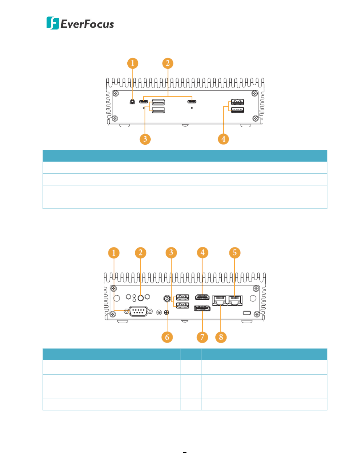
1.5 Front Panel...................................................................................................................... 5
1.1 Rear Panel ....................................................................................................................... 5
2. Hardware Installation ............................................................................................................. 7
2.1 How to Remove the Bottom Case................................................................................... 7
2.2 How to Install the WiFi Module ...................................................................................... 8
2.3 How to Remove the M.2 SSD and the Bracket ............................................................... 9
2.4 How to Install the M.2 SSD ........................................................................................... 10
2.5 How to Install the 2.5-inch Hard Drive ......................................................................... 11
2.6 How to Install the Memory Modules (DDR4) ............................................................... 13
3. Motherboard......................................................................................................................... 14
3.1 Motherboard Layout..................................................................................................... 14
3.2 Jumpers Setup............................................................................................................... 15
3.3 Onboard Headers and Connectors ............................................................................... 16
3.4 Installation of ROM Socket ........................................................................................... 18
3.5 Expansion Slot (M.2 Slots) ............................................................................................ 19
4. UEFI Setup Utility .................................................................................................................. 20
4.1 Introduction .................................................................................................................. 20
4.1.1 UEFI Menu Bar .......................................................................................................... 20
4.1.2 Navigation Keys......................................................................................................... 21
4.2 Main Screen .................................................................................................................. 22
4.3 Advanced Screen........................................................................................................... 23
4.3.1 CPU Configuration..................................................................................................... 24
4.3.2 Chipset Configuration ............................................................................................... 25
4.3.3 Storage Configuration............................................................................................... 26
4.3.4 Super IO Configuration ............................................................................................. 27
4.3.5 ACPI Configuration.................................................................................................... 28
4.3.6 USB Configuration..................................................................................................... 29
4.3.7 Trusted Computing ................................................................................................... 30
4.4 Hardware Health Event Monitoring Screen.................................................................. 31
4.5 Security Screen.............................................................................................................. 32
4.6 Boot Screen................................................................................................................... 33
4.7 Exit Screen..................................................................................................................... 35

eIVP-CFS-AI-D0000 AI Box
1
1. Introduction
The eIVP-TGU-AI-D0000 is an AI Box adopting Intel® 11th Gen Core™ i7/i5/i3 U-series processor.
The small footprint makes it suitable to fit on any desk or rear monitors by using the VESA hole
patterns.
This model comes with dual channel DDR4 SO-DIMM memory slots, supporting up to 64GB
memory. For storage, it has a SATA3.0 bay and a M.2 key M (2242/2260/2280) slot, which
supports PCIe x4 and SATA3 for SSD.
Connectivity-wise, the eIVP-TGU-AI-D0000 supports additional M.2 (key E 2230) slot for wireless
connection; one RS-232 COM port; and four USB 3.2 Gen 2 Type-A ports, two USB 3.2 Gen 2 type-
C ports and two USB 2.0 ports. For audio and video, the model provides an audio jack and display
outputs including HDMI and DP ports.
1.1 Features
•Fanless AI box
•11th Gen. Intel® Core™ i7/i5/i3/Celeron® U-series
•DDR4 3200 MHz 260-pin SO-DIMM x 2, up to 64GB
•USB 3.2 Gen2 x 6, USB 2.0 x 2
•M.2 Key M (2242/2260/2280) x 1, M.2 Key E (2230) x 1
•COM (RS232) x 1, SATA3 x 1
•GbE LAN x 1, 2.5GbE LAN x 1
•Quad displays: HDMI 2.0a x 1, DP 1.4 (2 from Type C) x 3
•TPM onboard
•19V/90W power adapter
•CE, FCC certified
Chapter
1

eIVP-CFS-AI-D0000 AI Box
2
1.2 Dimensions
53.3mm / 2.1"
50.5mm / 1.97"
109.45mm / 4.31"
171.8mm / 6.76"
1.3 Packing List
•System x 1
•DC19V/90W power adapter x 1
•M.2 screw x 2
•M.2 (2280) bracket with screw x 1 (installed on MB)
•VESA mount kit x 1
Note:
1. Equipment configurations and supplied accessories vary by country. Please consult your
local EverFocus office or agents for more information. Please also keep the shipping carton
for possible future use.
2. Contact the shipper if any items appear to have been damaged in the shipping process.

eIVP-CFS-AI-D0000 AI Box
3
1.4 Product Specifications
System
Processor 11th Gen. Intel
®
Core™ i7/i5/i3/Celeron
®
U-series
Main Memory DDR4 3200 MHz 260-pin SO-DIMM x 2, up to 64GB
Video
Format H.264 / H.265
Video Input Based on the installed software
EverFocus AiO NVR: up to 8ch
Video Output HDMI 2.0a x 1; DP 1.4 x 1
Audio
Audio Jack Audio jack x 1 (Mic-in, Line-out)
Recording
Format H.264 / H.265
Resolution 1920 x 1080 at 30fps (NTSC) / 25fps (PAL)
Storage
SATA SATA3.0 (6Gbps) x 1
mSATA n/a
RAID n/a
Others M.2 x 1 (KEY M, 2242/2260/2280) with PCIe x4 and SATA3 for SSD
Network
Ethernet LAN1: Intel® I219LM with 10/100/1000 Mbps
LAN2: Intel® I225LM with 10/100/1000/2500 Mbps
Wi-Fi / 3G / 4G Supported (optional)
GPS / CANBus n/a
I/O
Digital I/O n/a
Interface
Front I/O
Panel
Audio jack (Mic x 1, Line-out) x 1
USB 3.2 Gen2 (Type C, supports DP 1.4) x 2
USB 3.2 Gen2 (Type A) x 2
USB 2.0 (Type A) x 2

eIVP-CFS-AI-D0000 AI Box
4
Rear & Right-
Side I/O Panel
Power button x 1
LED indicator (HDD, power) x 2
COM (RS232) x 1
DC power input x 1
USB 3.2 Gen2 (Type A) x 2
HDMI 2.0a x 1; DP 1.4 x 1
GbE LAN x 1; 2.5GbE LAN x 1
Antenna port x 2
Security slot x 1
Expansion Slot M.2 Key E socket (2230) x 1 (with PCIe x1, USB 2.0 and CNVi for wireless)
Software Support
NVR Software EverFocus AiO NVR
General
Power Supply DC 19V, 90W (power adapter provided)
Dimensions
(W D H)
6.76" x 1.97" x 4.31" / 171.8 x 50.05 x 109.45 mm (without bracket)
Gross Weight 3.53lb (1.6kg)
Operating
T
32°F ~ 122°F (0°C ~ 50°C)
Storage Temp. -40°F ~ 185°F (-40°C ~ 85°C)
Storage
H idit
5%~90%, non-condensing
Certification CE, FCC Class A

eIVP-CFS-AI-D0000 AI Box
5
1.5 Front Panel
No. Description
1 Audio (Mic-in, Line-out)
2 2 x USB 3.2 Gen2 Ports (Type C, supports DP1.4 display output)
3 USB 3.2 Gen2 (Type A)
4 USB 2.0 (Type A)
1.1Rear Panel
No. Description No. Description
1 COM Port 5 RJ-45 (2.5G LAN)*
2 Power Button 6 DC-IN
3 2 x USB 3.2 Gen2 (Type A)
7 DisplayPort
4 HDMI
8 RJ-45 (1G LAN)*
* There are two LEDs on the LAN ports. Please refer to the table below for LAN port LED
indications.

eIVP-CFS-AI-D0000 AI Box
6
Activity / Link LED
Speed LED
Status
Description
Status
Description
1G/2.5G LAN
1G LAN
2.5G LAN
Off
No Link
Off
10Mbps connection
10Mbps connection
Blinking
Data Activity
Orange
100Mbps connection
100Mbps /1Gbps connection
On
Link
Green
1Gbps connection
2.5Gbps connection

eIVP-CFS-AI-D0000 AI Box
7
2. Hardware Installation
2.1 How to Remove the Bottom Case
1. Remove the four screws on the bottom case.
2. Then lift up and remove the bottom panel.
Chapter
2

eIVP-CFS-AI-D0000 AI Box
8
2.2 How to Install the WiFi Module
1. Locate the WiFi Module slot on the motherboard.
2. Carefully insert the WiFi Module into the slot.
3. Tighten the screw to secure the WiFi Module to the motherboard.

eIVP-CFS-AI-D0000 AI Box
9
2.3 How to Remove the M.2 SSD and the Bracket
1. Release the screw and carefully remove the M.2 SSD.
2. Release the screw and remove the bracket from the motherboard.

eIVP-CFS-AI-D0000 AI Box
10
2.4 How to Install the M.2 SSD
1. Locate the M.2 slot on the motherboard.
2. Carefully insert the M.2 SSD into the slot.
3. Tighten the screw to secure the M.2 SSD to the motherboard.

eIVP-CFS-AI-D0000 AI Box
11
2.5 How to Install the 2.5-inch Hard Drive
1. Remove the four screws on the bottom case. Then lift up and remove the bottom panel.
2. Attach the HDD cage to the bottom panel and secure it using the four screws.
3. Connect the SATA Data and Power Cable to the HDD.

eIVP-CFS-AI-D0000 AI Box
12
4. Connect the SATA Cable to the connector.
5. Then reinstall the bottom panel.

eIVP-CFS-AI-D0000 AI Box
13
2.6 How to Install the Memory Modules (DDR4)
1. Carefully insert the SO-DIMM memory modules into the slot at a 30-degree angle.
2. Push down until the modules snap into place.
Note:
1. The system requires DDR4 SO-DIMM.
2. For dual channel configuration, you always need to install identical (the same brand, speed,
size and chip-type) DDR4 SO-DIMM pairs.
3. The SO-DIMM only fits in one correct orientation. It will cause permanent damage to the
motherboard and the DIMM if you force the DIMM into the slot at incorrect orientation.

eIVP-CFS-AI-D0000 AI Box
14
3. Motherboard
3.1 Motherboard Layout
No. Description
No
Description
1 M.2 Key-M Socket (M2_M1) 5 Clear CMOS Header (CLRCMOS1)
2 M.2 Key-E Socket (M2_E1) 6 SATA3 Port (SATA3_0)
3 USB2.0 Connector (USB2_7_8) 7 SIO_AT1
4 COM Port Header (RS232) 8 System Panel Header (PANEL1)
Back Side
Power Button (PWR_BTN1 Battery Connector (BAT1)
FAN Connector (FAN1) ESPI Connector (ESPI)
Chapter
3

eIVP-CFS-AI-D0000 AI Box
15
3.2 Jumpers Setup
The illustration shows how jumpers are setup. When the jumper cap is placed on pins, the jumper
is “Short”. If no jumper cap is placed on pins, the jumper is “Open”. The illustration shows a 3-pin
jumper whose pin1 and pin2 are “Short” when jumper cap is placed on these 2 pins.
Short Open
Clear CMOS Jumper
(3-pin CLRCMOS1)
(see p.14, No.5)
1-2: Auto Clear CMOS
2-3: Clear CMOS
SIO_AT1
(2-pin SIO_AT1)
(see p.14, No.7)
Open: ATX Mode
Short: AT Mode
Note:
CLRCMOS1 allows you to clear the data in CMOS. To clear and reset the system parameters to
default setup, please turn off the computer and unplug the power cord from the power supply.
After waiting for 15 seconds, use a jumper cap to short pin2 and pin3 on CLRCMOS1 for 5
seconds. However, please do not clear the CMOS right after you update the BIOS. If you need to
clear the CMOS when you just finish updating the BIOS, you must boot up the system first, and
then shut it down before you do the clear-CMOS action. Please be noted that the password,
date, time, user default profile and MAC address will be cleared only if the CMOS battery is
removed.
CLRCMOS1 allows you to clear the data in CMOS automatically when AC power on. The data in
CMOS includes system setup information such as system password, date, time, and system
setup parameters. To clear and reset the system parameters to default setup, please turn off
the computer and unplug the power cord, then use a jumper cap to short the pins on
CLRCMOS1.
Table of contents
Other EverFocus Desktop manuals