TABLE OF CONTENTS
1. INTRODUCTION................................................................................................................................................... 4
2. FEATURES ............................................................................................................................................................. 4
3. COMPATIBLE DEVICES ..................................................................................................................................... 4
4. DELIVERY SCOPE ............................................................................................................................................... 4
5. OPERATING ELEMENTS.................................................................................................................................... 5
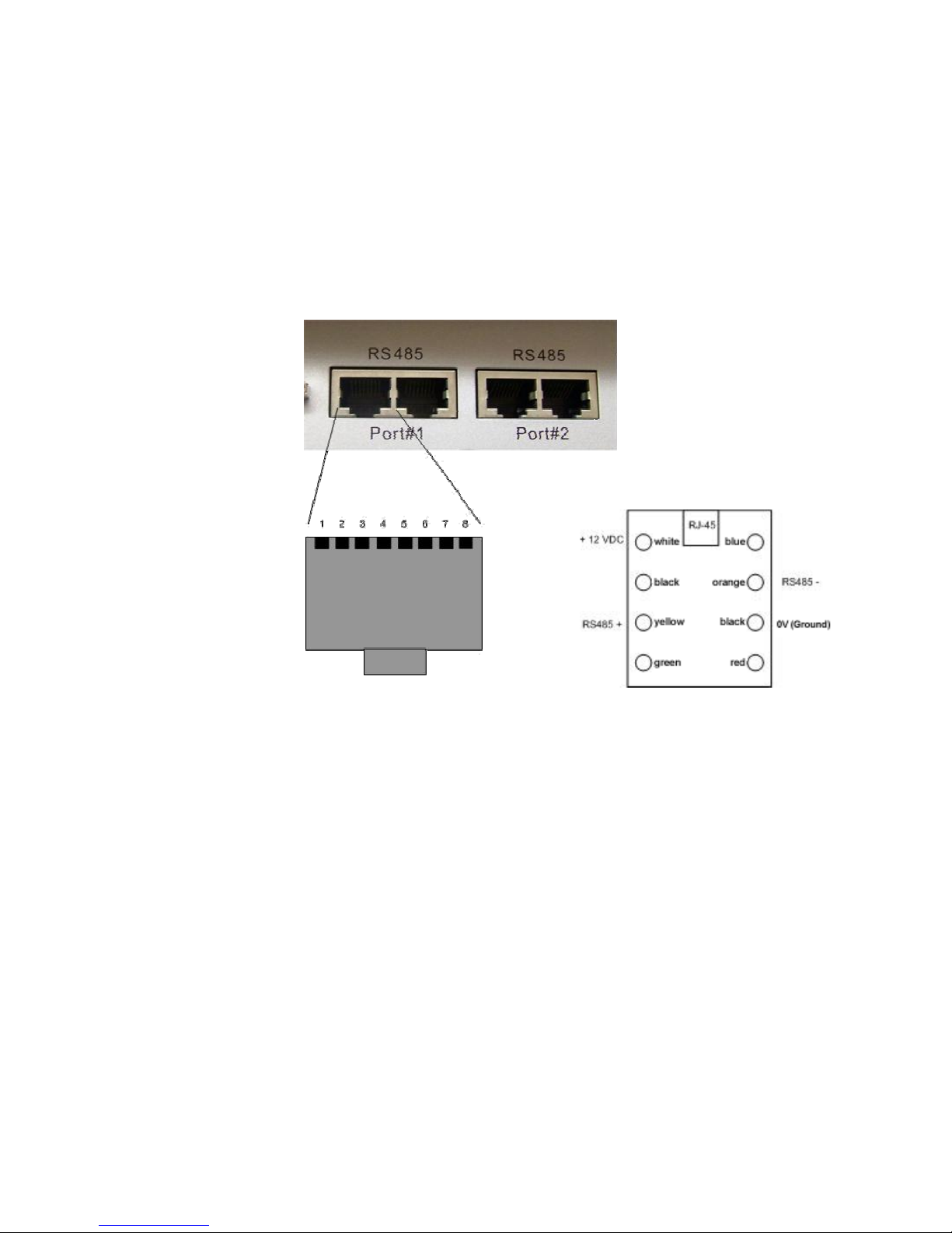
6. KEYBOARD CONNECTORS............................................................................................................................... 6
7. INSTALLATION..................................................................................................................................................... 7
7.1.
G
ENERAL
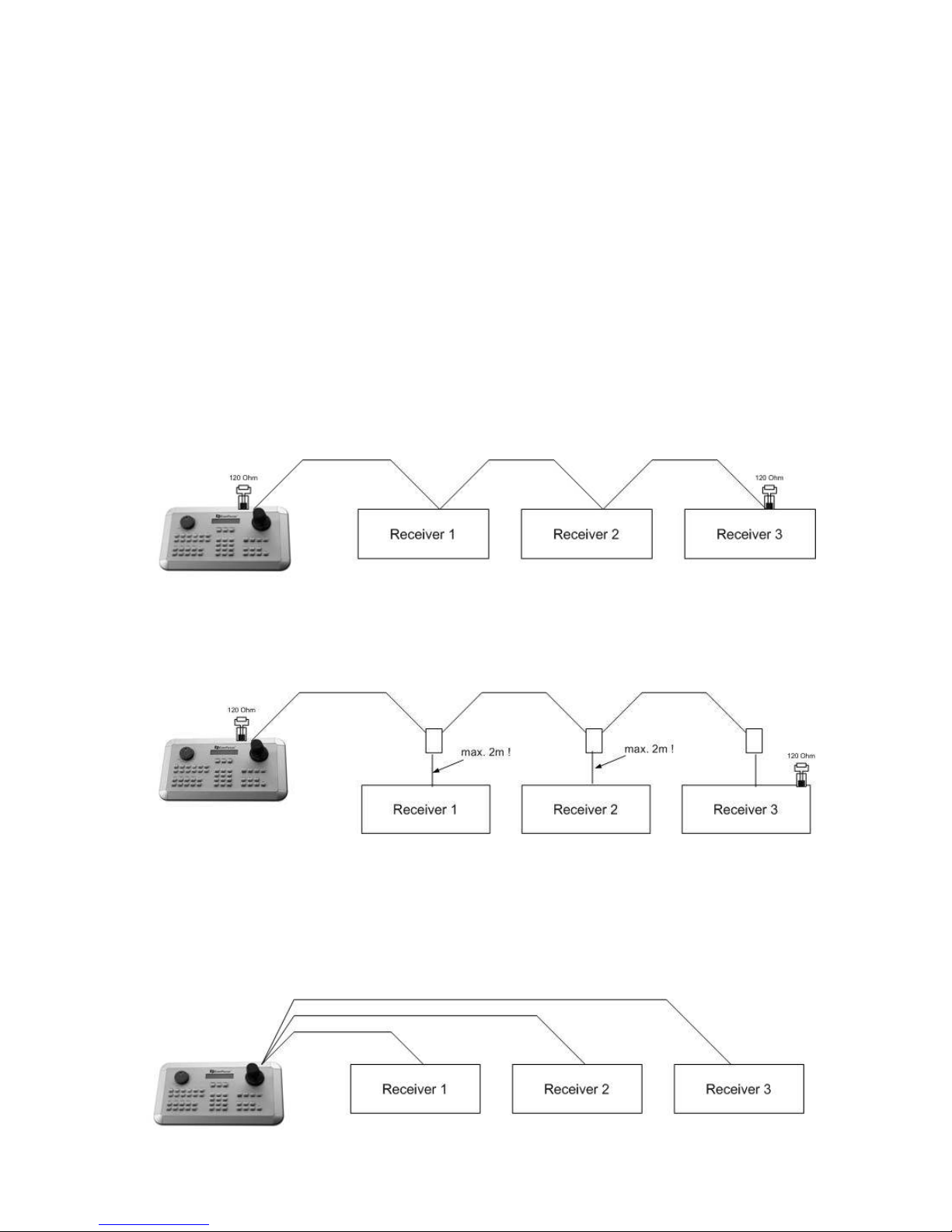
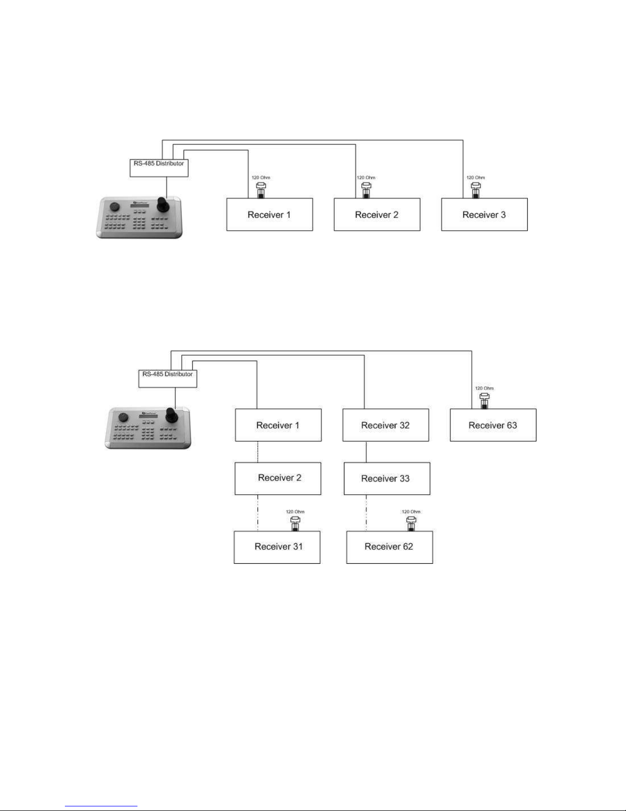
RS-485
BUS INSTALLATION
................................................................................................................. 7
7.2.
EPTZ
500
/
1000
/
3000
S
PEED DOME CAMERA CONNECTION
............................................................................. 9
7.3
ED-2200,
ED-2250,
S
AMSUNG
SCC- 41,
SCC- 43
,
SCC- 405
CONNECTION
................................................... 9
7.4.
C
ONNECTION OF
P
ELCO
-D
/
-P
PROTOCOL
-
COMPATIBLE DEVICES
..................................................................... 10
7.5
EDSR
/
EDR/
EDVR
SERIES
’
DVR
CONNECTION
.............................................................................................. 11
7. .
C
ONNECTION OF SEVERAL KEYBOARDS
............................................................................................................ 13
7.7.
S
TARTUP
............................................................................................................................................................ 13
8. MENU SETTINGS ............................................................................................................................................... 14
8.1.
M
ENU STRUCTURE
............................................................................................................................................ 14
8.2.
COM
PORT
SETTING
-
RS-485
INTERFACE SETTING
...................................................................................... 15
8.3.
DEVICE
SETTING.......................................................................................................................................... 15
8.3.1.
C
AMERA SETTING
.................................................................................................................................15
8.3.2.
C
ALL AND MATRIX MONITOR SETTING
.....................................................................................................16
8.3.3.
DVR
S
ETTING
.....................................................................................................................................17
8.3.4.
C
AMERA
L
IST
&
D
ELETE
.......................................................................................................................17
8.3.5.
M
ONITOR
L
IST
&
D
ELETE
......................................................................................................................18
8.3.6.
DVR
L
IST
&
D
ELETE
............................................................................................................................18
8.3.7.
N
ON
-
LISTED DEVICES
...........................................................................................................................19
8.4.
KEYBOARD
SETTING .................................................................................................................................. 19
8.4.1.
S
UB
K
E BOARD
S
ETTING
.....................................................................................................................19
8.4.2.
MENU
P
ASSWORD
..............................................................................................................................19
8.4.3.
L
OCK PASSWORD
.................................................................................................................................20
8.4.4.
B
UZZER
ON/OFF ................................................................................................................................20
8.4.5.
J
O STICK CALIBRATION
........................................................................................................................20
8.4.6.
K
E PAD TEST
.......................................................................................................................................21
8.4.7.
J
OG
&
S
HUTTLE TEST
...........................................................................................................................21
8.4.8.
L
OAD DEFAULT SETTING
........................................................................................................................21
8.4.9.
F
IRMWARE UPDATE
..............................................................................................................................21
9. OPERATION......................................................................................................................................................... 22
9.1.
DVR
OPERATION
............................................................................................................................................... 22
9.1.1.
DVR
SELECTION
..................................................................................................................................22
9.1.2.
DVR
MAIN FUNCTIONS
.........................................................................................................................23
9.1.3.
M
AIN MONITOR
(MAIN)
OPERATION IN
DVR
MODE
.................................................................................24
9.1.4.
C
ALL AND MATRIX MONITOR OPERATION IN
CAM-MON
MODE
.................................................................24
9.2.
SPEED
DOME
/
TELEMETRY
RECEIVER
OPERATION
/
SETUP ............................................................. 25
9.2.1
E
VER
F
OCUS
EPTZ
SERIES
...................................................................................................................26
9.2.1.1. EPTZ on-screen display ........................................................................................................................................27